A Robotics Coordination Case Study
Davide Brugali, Luca Gherardi, Patrizia Scandurra
Abstract— Robotics software require and provide a number of different functionalities, which are typically encapsulated in components that cooperate and compete in order to control the behavior of a robot. Cooperation and competition are forms of interaction among concurrent activities and so they have to be coordinated. In order to achieve a good level of reusability and flexibility the coordination and the computation (how the component provides the service) need to be managed separately. According to this principle we propose an innovative ap-proach based on two frameworks that are widespread in other domains such as the web services. We will show by means of a use case how we have implemented the component through the Service Component Architecture and how we have managed the coordination by means of the Abstract State Machine. In particular we will illustrate that is possible to change the coordination policy without modifying the implementation of the services provided by the component.
I. INTRODUCTION
Robots are controlled through complex software, which re-quires and provides a number of different functionalities such as motion planning, kinematics, perception and actuation. According to the Component Based Software Engineering principles [1][2], these functionalities can be encapsulated into components. These components improve the level of reusability and reduce the effort and the time needed to develop applications.
The implementation of the components defines how the functionalities are realized. This concern is called compu-tation and is related with the data processing algorithms required by an application [3]. Another important concern, which is orthogonal to the computation, is the coordination. Coordination is more concerned with the interaction of the components [3] and so it defines when the functionalities are used. Components can typically interact in two ways: they cooperate with each other in order to achieve a common goal and at the same time compete for using shared resources such as memory, CPU and external devices (e.g. sensors and actuators). Cooperation and competition are forms of interactions among concurrent activities, which overlap in the time and are interleaved with one other on a single processor. Correct interleaving of concurrent activities can be reached by means of coordination algorithms.
In the context of the European Project BRICS [4] we have chosen two different frameworks in order to model and
The work described in this paper has been funded by the European Community’s Seventh Framework Programme (FP7/2007-2013) under grant agreement no. FP7-ICT-231940-BRICS (Best Practice in Robotics).
D. Brugali, L. Gherardi and P. Scandurra are with the Dept. of Information Technology and Mathematics, University of Bergamo, 24044 Dalmine,
Italy [email protected], [email protected],
implement these two concerns. Regarding the computation we have adopted the component model offered by the Service Component Architecture project [5]. SCA is a set of specifi-cations which describe a model for building applispecifi-cations and systems using a Service-Oriented Architecture. Coordination instead is managed by means of the Abstract State Ma-chines (ASM) formal method. ASM is an operational (read: executable) formalism that provides accurate yet practical industrially viable behavioral semantics for pseudo-code on arbitrary data structures. This specification method is tunable to any desired level of abstraction, and besides ASMs comes with a rigorous mathematical foundation [6], it provides rigor without formal overkill.
In particular we adopt a service-oriented flavor of the ASM formalism, named SCA-ASM. SCA-ASM is a formal and executable modeling language based on the open standard model SCA for heterogeneous service-oriented component assembly and on the ASM formal method, which is able to model behavioral notions of service interactions, orchestra-tions, compensaorchestra-tions, and the services internal behavior (see the preliminary work [7]).
The paper illustrates by means of a case study how we have defined a component-based system using Java and the SCA framework and how we have coordinated it using the Abstract State Machines.
The paper is structured as follows.
Section II presents the case study and proposes a high level solution. Section III briefly introduces the ASM and describes how the solution presented in section II can be realized through ASM. Section IV illustrates a SCA imple-mentation of the case study. Finally section V draws the relevant conclusion.
II. THEUSECASE
We propose a simple scenario where a laser scanner offers its services to different clients, which compete for the use of this shared resource.
A. The problem
The scenario is defined by the following three participants, which are illustrated in figure 1.
• A Laser Scanner, which executes scans of the environ-ment on demand and writes the acquired values on a data buffer. A scan is a sequence of measures executed in a single task (for example 360 values, one for each degree). We suppose that the Laser Scanner allows its client to request a scan from an initial angle (start) to a finale one (end) defined as the number of steps between start and end.
• A 3D Perception application, which requests the mea-sures to the Laser Scanner in order to generate a set of meshes that describe the surface of the objects present in the environment.
• An Obstacle Avoidance application, which requests the measures to the Laser Scanner in order to detect the obstacles along the robot path.
Laser Scanner Client 1 3D Perception Client 2 Obstacle Avoidance
Fig. 1. The three participants
B. The requirements
The proposed scenario is subjected to the following re-quirements:
1) The laser scan is an activity that requires an amount of time in order to be completed. This time is not fixed, and depends on the number of measures requested by the client. During this time the Client could have the need of executing other operations and so it doesn’t have to be blocked while it waits.
2) A client could request a single scan or multiple scans (for example 4 scans composed each one by 20 mea-sures).
3) While the Laser Scanner is executing a scan requested by a client A, a client B could require another scan. These requests have to be managed according to one of the following request management policies:
• Policy 1: Discard the scan request.
• Policy 2: Queue the scan request.
According to these requirements it is possible to imagine at least the following three situations, in which the Laser Scanner receives requests from its client.
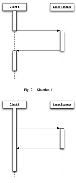
The first situation is described in figure 2. The client requests a scan to the Laser Scanner and then it waits until the end of the scan process. When the Laser Scanner finishes its work it returns to the client the measures. In this case the request is synchronous.
The second situation is described in figure 3. The client requests a scan to the Laser Scanner and then it continues to execute its work. In this case the request has to be asynchronous.
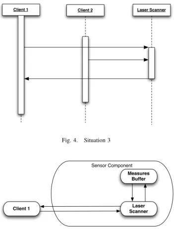
The third situation is described in figure 4. In this case the Client 1 acts as in the situation two. However while the Laser Scanner is executing the scan requested by the Client 1, the Client 2 sends another request to the Laser Scanner. This example highlights how different clients could
Client 1 Laser Scanner
Fig. 2. Situation 1
Client 1 Laser Scanner
Fig. 3. Situation 2
simultaneously access to the services offered by the Laser Scanner and so the need of managing these different requests. C. A high-level solution
The first two situations don’t require a simultaneously access to the Laser Scanner services and so the Client and the Laser Scanner can directly interact. Figure 5 illustrates how the two parts interact. The Client 1 requests a scan to the Laser Scanner, which writes each measure on a Measures Buffer. Then, when the scan is finished:
• The Laser Scanner returns to the Client 1 the measures
— Situation 1.
• The Laser Scanner notifies the Client that it has finished
its work. After that, the client requests the measures to the Laser Scanner — Situation 2.
The third situation instead presents a simultaneously ac-cess to the Laser Scanner services. In this case the in-teractions between the clients and the Laser Scanner have to be managed by a third part: a coordinator. The Sensor
Client 2 Laser Scanner Client 1 Fig. 4. Situation 3 Laser Scanner Measures Buffer Client 1 Sensor Component
Fig. 5. High-level solution for the situations 1 and 2
Coordinator is in charge of forwarding the clients requests to the Laser Scanner and so it has to manage the concurrent access of the clients. Figure 6 illustrates how it works. It can be summarized in the following list:
1) The Sensor Coordinator receives a request of scan from a client.
2) According to the Sensor Coordinator policy (see above) the new request could be discarded, queued or forwarded to the Laser Scanner.
3) When the request is forwarded, the Laser Scanner starts the scanning work and sends a notification to the Sensor Coordinator (Ack) in order to inform it that the scan has started.
4) The Laser Scanner writes each measure on the Mea-sures Buffer until the final angle is reached.
5) The Laser Scanner sends a notification to the Sensor Coordinator (Done) in order to inform it that the scan is finished.
6) The Coordinator sends a notification to the client in order to inform it that the new measures are available on the Buffer.
7) The client accesses the Measures Buffer in order to read the measures.
Depending on the number of scan requested the Sensor Coordinator will forward to the Laser Scanner one or more single scans. Laser Scanner Measures Buffer Client 2 Sensor Coordinator Client 1 Sensor Component
Fig. 6. High-level solution for the situation 3
The Sensor Coordinator policy can be defined by means of the finite state machine. A first version is reported in figure 7. It implements the request management policy 1: if a request is received while the laser is already scanning the new request will be discarded. SCANNING IDLE BUSY scan(from, nSteps) "Ack" "Done"
Fig. 7. Sensor Coordinator Finite State Machine, version 1
The sates have the following meaning:
• IDLE: the Laser Scanner is idle and is ready for a new scan. In case of a scan request the Sensor Coordinator forwards it to the Laser Scanner. The Sen-sor Coordinator enters this state on the initialization or when the Laser Scanner returns a “Done” notification.
• BUSY: the laser scanner is executing the operations
needed for starting the scan. The Sensor Coordinator enters this state when it has sent a scan request to the Laser Scanner. If a new scan request is received the sensor coordinator discards it.
• SCANNING: the laser is scanning and writing the measures on the Measures Buffer. The Sensor Coor-dinator enters this state when the scan request is sent to the Laser Scanner and it has returned the “Ack” notification. If a new scan request is received the sensor coordinator discards it.
The finite state machine presented above allows a client to request a single scan. It is possible to refine it in order to support multiple scan requests. In this way the client will send a single message to the Sensor Coordinator, asking it n scans. In turn, the Sensor Coordinator will forward n single scan requests to the Laser Scanner.
Figure 8 illustrates the new finite state machine. To be noticed that we have changed the Sensor Coordinator policy without modifying the functionality offered by the Laser
Scanner. Furthermore this version, as well as the first, is able to satisfy single scan requests.
SCANNING IDLE
BUSY scan(from, nSteps, nScans)
"Ack" "Done" && remScans > 0 "Done" && remScans = 0
Fig. 8. Sensor Coordinator Finite State Machine, version 2
The sates have the same meaning described above. What changes are the transition rules:
• IDLE → BUSY: the transition is triggered when the Sensor Coordinator receives a scan request.
• BUSY → SCANNING: the transition is triggered when the Laser Scanner sends an “Ack” notification to the Sensor Coordinator.
• SCANNING → BUSY: the transition is triggered when the Laser Scanner sends a “Done” notification to the Sensor Coordinator and the number of remaining scans (“remScans”) is greater than 0.
• SCANNING → IDLE: the transition is triggered when
the Laser Scanner sends a “Done” notification to the Sensor Coordinator and there are not remaining scans to execute.
Figure 9 shows the finite state machine that implements the policy 2: if a request is received while the laser is already scanning the new request will be queued. Also in this case the states and the functionalities provided by the laser scanner are the same. What changes are the transition rules.
SCANNING IDLE
BUSY scan(from, nSteps, nScans)
"Ack"
("Done" AND remScans > 0) OR ("Done" AND remScans = 0
AND pendingReq > 0) "Done" AND
remScans = 0 AND pendingReq = 0
scan(from, nSteps , nScans)
scan(from, nSteps , nScans)
Fig. 9. Sensor Coordinator Finite State Machine, version 3
The new transitions are described in the following list.
• IDLE → BUSY: the transition is triggered when the Sensor Coordinator receives a scan request.
• BUSY → BUSY: the transition is triggered when the Sensor Coordinator receives a scan request. The request is queued.
• BUSY → SCANNING: the transition is triggered when the Laser Scanner sends a “Ack” notification to the Sensor Coordinator.
• SCANNING → BUSY: the transition is triggered when
– the Laser Scanner sends a “Done” notification to the Sensor Coordinator and the number of remain-ing scans is greater than 0, or
– the Laser Scanner sends a “Done” notification to the Sensor Coordinator, there are not remaining scans to execute and the number of pending re-quests in queue is greater then 0.
• SCANNING → SCANNING: the transition is triggered
when the Sensor Coordinator receives a scan request. The request is queued.
• SCANNING → IDLE: the transition is triggered when the Laser Scanner sends a “Done” notification to the Sensor Coordinator, there are not remaining scans to execute and there are not pending requests in queue. The next section will illustrate how we have modeled these finite state machines through the ASM language.
III. THEASMSPECIFICATION OF THEUSECASE
The Sensor Coordinator was implemented using the SCA-ASM formalism. In the following an SCA-ASM-based (abstract) implementation of the Sensor Coordinator is reported. A. The Abstract State Machine method in a nutshell
Abstract State Machines (ASMs) are an extension of Finite State Machines (FSMs) [6] where unstructured control states are replaced by states comprising arbitrary complex data. The states of an ASM are multi-sorted first-order structures, i.e. domains of objects with functions and predicates (boolean functions) defined on them. The transition relation is spec-ified by rules describing how functions change from one state to the next. Basically, a transition rule has the form of guarded update if Condition then Updates where Updates is a set of function updates of the form f (t1, . . . , tn) := t
which are simultaneously executed when Condition is true. There is a limited but powerful set of rule constructors, reported in Table I, that allow to express simultaneous parallel actions (par) of a single agent, either in an atomic way, Basic ASMs, or in a structured and recursive way, Struc-tured or Turbo ASMs, by sequential actions (seq), iterations (iterate, while, recwhile), and submachine invoca-tions returning values. Appropriate rule constructors also allow non-determinism (existential quantification choose) and unrestricted synchronous parallelism (universal quantifi-cation forall). Furthermore, the ASM method supports a generalization where multiple agents interact in parallel in a synchronous/asynchronous way, Synch/Asynch Multi-agent ASMs. In this last model, the predefined variable self is interpreted by each agent as itself.
Based on [6], an ASM can be defined as the tuple: (header, body, main rule, initialization)
Skip rule skip do nothing
Update rule f (t1, . . . , tn) := t update the value of f at t1, . . . , tnto t Block rule par R1. . . Rnendpar rules R1. . . Rnare executed in parallel
Seq rule seq R1. . . Rnendseq rules R1. . . Rnare executed in sequence without exposing intermediate updates Conditional rule it φ then R1else R2endif if φ is true, then execute rule R1, otherwise R2fires
Iterate rule while φ do R execute rule R until φ is true
Forall rule forall x with φ do R execute R in parallel for each x satisfying φ
Choose rule choose x with φ do R(x) choose an x satisfying φ and then execute R
Macro call rule R[x1, . . . , xn] call rule R with parameters x1, . . . , xn
Let rule let x = t in R assign the value of t to x and then execute R
TABLE I
ASMRULE CONSTRUCTORS
The header contains the name of the ASM and its signa-ture1, namely all domain, function and predicate declarations. Function are classified as derived functions, i.e. those coming with a specification or computation mechanism given in terms of other functions, and basic functions which can be static (never change during any run of the machine) or dynamic(may change as a consequence of agent actions or updates). Dynamic functions are further classified into: mon-itored (only read, as events provided by the environment), controlled (read and write), shared (read and write by an agent and by the environment or by another agent) and output (only write) functions.
The body of an ASM consists of (static) domain and (static/derived) function definitions according to domain and function declarations in the signature of the ASM. It also contains declarations (definitions) of transition rules. The body may also contain definitions of invariants to assume over domains and functions of the ASM.
The (unique) main rule is a transition rule and represents the starting point of the machine program (i.e. it calls all the other ASM transition rules defined in the body). The main rule is closed (i.e. it does not have parameters) and since there are no free global variables in the rule declarations of an ASM, the notion of a move does not depend on variable assignment, but on the machine state.
The initialization of an ASM is a characterization of the initial states. An initial state defines initial values for domains and functions declared in the ASM signature.
Executingan ASM means executing its main rule starting from a specified initial state. A computation of an ASM M is a finite or infinite sequence S0, S1, . . . , Sn, . . . of states
of M , where S0is an initial state and each Sn+1is obtained
from Sn by firing simultaneously all of the transition rules
which are enabled in Sn.
A lightweight notion of module is also supported. An ASM moduleis an ASM (header, body) without a main rule, without a characterization of the set of initial states, and the body may have no rule declarations. A module is written as an ASM with the keyword asm replaced by the keyword
module.
An open framework, the ASMETA tool set [8], based on the Eclipse/EMF modeling platform and developed around
1Importand export clauses can be also specified for modularization.
the ASM Metamodel, is also available for editing, exchang-ing, simulatexchang-ing, testexchang-ing, and model checking models. B. The ASM-SCA formalism
In addition to the ASM rule constructors, other commands capturing service behavioral aspects have been provided (see [7], [9] for more details) and formalized in terms of ASMs concepts as further actions offered by the SCA-ASM language, including constructs to express the control flow of component’s tasks, as well as primitive for services or-chestration and interaction. Some of these actions correspond to predefined ASM rules whose AsmetaL implementation is provided in terms of an external library, named Common-Behavior, to be imported as part of a SCA-ASM module. In particular, external services are invoked in a synchronous and asynchronous manner through the following interaction (or communication) primitives:
• wsend[lnk,R,snd]: Sends data “snd” without blocking to the partner link “lnk” in reference to the service operation “R” (no acknowledgment is expected).
• wreceive[lnk,R,rcv]: Receives data in the location “rcv”
from the partner link “lnk” in reference to the service operation “R; it blocks until data are received. No acknowledgment is expected.
• wsendreceive[lnk,R,snd,rcv]: In reference to the service operation “R, some data “snd are sent to the partner link “lnk, then the action waits for data to be sent back, which are stored in the receive location “rcv; no acknowledgment is expected for send and receive.
• wreplay[lnk,R,snd] Returns some data “snd” to the partner link “lnk”, as response of a previous “R” request received from the same partner link; no acknowledg-ment is expected.
These communication primitives rely on a dynamic do-main Message that represents message instances managed by an abstract message passing mechanism, abstracting, therefore, from the SCA notion of binding. We assume only that components communicate over links according to the semantics of the communication commands reported above and a message encapsulates information about the partner link and the referenced service name and data transferred. A data binding mechanism also guarantees a matching between ASM data types and Java data types, including structured data.
C. The Sensor Coordinator Abstract State Machine - Policy 1
The following listings report the ASM implementation of the Sensor Coordinator FSM depicted in figure 8 (request management policy 1). To this purpose, the AsmetaL textual notation to write ASM models within the ASMETA tool-set is used. Two grammatical conventions must be recalled: a variable identifier starts with an initial $; a rule identifier begins with “r ”.
Listing 1 shows the first lines of the ASM implementation. The import clauses include the ASM modules of the provided service interfaces (in our case SensorCoordinating and Even-tObserving) and required interfaces (in our case the Laser-Scanning interface) of the component, annotated, respec-tively, with “@Provided” and “@Required”. The “@Main-Service” annotation when importing the SensorCoordinating interface denotes the main service (read: main component’s agent) that is responsible for initializing the component’s state (in the predefined “r init” rule) and, eventually, for the start-up of the other agents by assigning programs to them. The signature of the machine contains declarations for:
• References (shared functions annotated with @Refer-ence), which are abstract access endpoints to services.
• Back references to requester agents (shared functions annotated with @Backref ).
• Declarations of the following ASM domains and func-tions, which are used by the component for internal computation only.
– The enumeration domain “State” defines the possi-ble states of the ASM shown in section II-C. – The variable “ctl state” stores the current control
state of the ASM.
– The variable “paramScan” is used to store the input parameters of the “request” function.
– The variable “from” is used to store the start position of a scan request received from a client. – The variable “steps” is used to store the number
of measures that compose a scan request received from a client.
– The variable “remScans” is used to store the num-ber of scans that are requested by a client. – The variable “event” is used to store the input
parameter of the “update” function.
1 module SensorCoordinator 2 importSTDL/StandardLibrary 3 importSTDL/CommonBehavior 4 5 //@MainService 6 importSensorCoordinating 7 //@Provided 8 importEventObserving 9 //@Required 10 importLaserScanning 11 export * 12 13 signature: 14 //@Reference
15 shared laserScanning: Agent −> LaserScanning 16 //@Backref
17 shared clientSensorCoordinating: Agent −> Agent
18 //@Backref
19 shared clientEventObserving: Agent −> Agent 20
21 enum domain State= {IDLE | BUSY | SCANNING} 22 //Internal properties
23 controlled ctl_state: Agent −> State
24 controlled paramScan: Agent −> Prod(Integer,Integer,Integer) 25 controlled from: Agent −> Integer
26 controlled steps: Agent −> Integer 27 controlled remScans: Agent −> Integer 28 controlled event: Agent −> String
Listing 1. The ASM implementation header
The body of the ASM, which starts with the key-word “definitions:” includes definitions of services (ASM transition rules annotated with @Service) “r request” and “r update”, the definition of the main transition rule “r SensorCoordinator” (that takes by convention the same name of the component’s module) and the transition rule with the predefined name “r init” that is in turn invoked in the initialization rule of the container composite to initialize the internal state (controlled functions). Another utility rule, named “r acceptRequest”, has been introduced for modu-larization purposes and to advance the control state of the machine according to the arriving service requests properly. Listing 2 reports the body of the “r request” rule. It is in charge of requesting a scan to the laser scanner. When the rule is called, it executes the following operations in a parallel way:
1) Sets the state of the ASM to BUSY.
2) Stores the parameters of the requested scan in the variables “from”, “steps” and “remScans”.
3) Calls the function “scan”, which is provided by the service Laser Scanning.
1 definitions://definitions of named ASM transition rules
2 //@Service
3 rule r_request($a in Agent,$from in Integer,$steps in Integer, $nScans in Integer)= 4 par 5 ctl_state($a) := BUSY 6 from($a) := $from 7 steps($a) := $steps 8 remScans($a) := $nScans − 1
9 r_wsend[laserScanning($a),”r scan(Agent,Integer,Integer)”,($from, $steps)]
10 endpar
Listing 2. The ”r request” rule
Listing 3 reports the body of the “r update” rule. It is in charge of receiving the notification from the laser scanner and updating the control state of the ASM. When the rule is called, it executes the following operations:
1) If the current control state is BUSY and the notification is an “Ack”: the rule sets the control state to SCAN-NING.
2) If the current control state is SCANNING and the notification is a “Done” and the number of remaining scans is greater than 0, the rule executes the following operations in a parallel way:
• Sets the control state to BUSY.
• Decrements the number of remaining scans.
• Calls the function “scan”, which is provided by the service Laser Scanning.
3) If the current control state is SCANNING and the notification is a “Done” and there are not remaining scans to do: the rule sets the control state to IDLE.
1 //@Service
2 rule r_update($a in Agent, $event in String) = 3 if(ctl_state($a)=BUSY and $event=”Ack”) 4 then ctl_state($a) := SCANNING
5 else if(ctl_state($a)=SCANNING and $event=”Done”and remScans( $a)>0)
6 //continue with next scan
7 then par
8 ctl_state($a) := BUSY
9 remScans($a) := remScans($a)−1
10 r_wsend[laserScanning($a),”r scan(Agent,Integer,Integer)”,(from($a), steps($a))]
11 endpar
12 else if(ctl_state($a)=SCANNING and $event=”Done”and remScans( $a)=0)
13 then ctl_state($a) := IDLE 14 endif endif endif
Listing 3. The ”r update” rule
Listing 4 reports the body of the “r acceptRequest” rule. It is in charge of processing the request received from the clients of the coordinator and so it receives as input a string, which contains the request. When the rule is called, it sequentially executes the following operations:
1) If the client has requested a new scan(r request): a) It removes the request from the requests stack
(operation “r wreceive”) and stores the input pa-rameters in the variable “paramScan”.
b) If the parameters are defined (condition “isDef ”) the rule calls the rule “r request” (see above) 2) If the Laser Scanner has sent a notification (r update):
a) It removes the request from the requests stack (operation “r wreceive”) and stores the input pa-rameter in the variable “event”.
b) If the parameter is defined the rule calls the rule “r update” (see above).
The rule is implemented in such a way that all the scan requests received while the scanner is already scanning are discarded (that’s what the policy 1 defines).
1 rule r_acceptRequest($a in Agent, $r in String) =
2 if(ctl_state($a)=IDLE and $r=”r request(Agent,Integer,Integer,Integer)”)
3 then seq 4 //first scan 5 r_wreceive[clientSensorCoordinating($a),”r request(Agent, Integer,Integer,Integer)”,paramScan($a)] 6 if(isDef(paramScan($a))) 7 then 8 r_request[$a,first(paramScan($a)),second(paramScan($a)), third(paramScan($a))] 9 endif 10 endseq
11 else if(not ctl_state($a)=IDLE and $r=”r update(Agent,String)”)
12 then seq 13 r_wreceive[clientEventObserving($a),”r update(Agent,String)”, event($a)] 14 if(isDef(event($a))) 15 then r_update[self,event($a)] 16 endif 17 endseq 18 endif endif
Listing 4. The ”r acceptRequest” rule
Listing 5 reports the body of the “r SensorCoordinator” rule. It is the main rule of the agent and is called every times a client requests a service offered by the Sensor Coordinator. This rule simply forwards the request to the “r acceptRequest” rule (see above).
1 //Main agent's program
2 rule r_SensorCoordinator=
3 let($r = nextRequest(self))//Select the next request(if any)
4 inifisDef($r)
5 then r_acceptRequest[self,$r]//Handle the request $r
6 endif
7 endlet
Listing 5. The ”r SensorCoordinator” rule
Listing 6 reports the body of the “r init” rule. It is called in order to initialize the agent. This rule simply sets the status of the agent to READY, the control state to IDLE and initializes the scan parameters to 0.
1 //Rule invoked for the startup of the components main agent
2 rule r_init($a in SensorCoordinating) =//to initialize the components state 3 par 4 status($a) := READY 5 ctl_state($a) := IDLE 6 from($a) := 0 7 steps($a) := 0 8 remScans($a) := 0 9 endpar
Listing 6. The ”r init” rule
D. The Sensor Coordinator Abstract State Machine - Policy 2
In this section we illustrate how the abstract state machine presented above can be modified in order to implements the request management policy 2 (figure 9).
Listing 7 shows the new implementation of the rule “r acceptRequest”. The lines 1-15 are the same of the previ-ous implementation. A third “if ” condition was added (lines 16-20) in order to manage the requests received while the control state is different from IDLE. In fact, when the control state is not IDLE and the request received is a scan request, the rule sequentially executes the following operation:
• It removes the request from the requests stack (operation “r wreceive”) and stores the input parameters in the variable “paramScan”.
• It puts the parameters in a queue called “pendingRe-quests” (operation “append”). This queue is defined in the header of the state machine and is the equivalent of an array which stores triplets of integers (the three parameters of a scan request).
All what is needed to queuing the scan requests stays in this rule. Indeed, as mentioned above, this is the rule that implements the request management policy. The changes in the rule “r update” are instead necessary in order to manage the requests queue.
1 rule r_acceptRequest($r in String) =
2 if(ctl_state(self)=IDLE and $r=”r request(Agent,Integer,Integer,Integer)”) 3 then seq//first scan
4 r_wreceive[clientSensorCoordinating(self),”r request(Agent, Integer,Integer,Integer)”,paramScan(self)]
5 if(isDef(paramScan(self)))//direct service invocation
6 then r_request[self,first(paramScan(self)),second( paramScan(self)),third(paramScan(self))]
7 endif
8 endseq
9 else if(not ctl_state(self)=IDLE and $r=”r update(Agent,String)”)
10 then seq 11 r_wreceive[clientSensorCoordinating(self),”r update(Agent, String)”,event(self)] 12 if(isDef(event(self))) 13 then r_update[self,event(self)] 14 endif 15 endseq
16 else if(not ctl_state($a)=IDLE and $r=”r request(Agent,Integer,Integer, Integer)”)
17 then seq//first scan
18 r_wreceive[clientSensorCoordinating($a),”r request(Agent, Integer,Integer,Integer)”,paramScan($a)]
19 append(pendingRequests($a), (first(paramScan($a)),second( paramScan($a)),third(paramScan($a)))
20 endseq
21 endif endif endif
Listing 7. The ”r acceptRequest” rule - Policy 2
Listing 8 illustrates how the implementation of the “r update” rule was changed. The lines 1-10 are the same of the previous implementation. The third “if ” condition was modified and split in two new conditions by adding a control on the number of pending requests. The following list describes the lines 11-20
1) If the current control state is SCANNING and the notification is a “Done” and there are not remaining scans to do and the number of pending requests is greater than 0: the rule sequentially
a) removes the first request from the queue, b) calls the rule “r request” by passing the
parame-ters retrieved from the queue.
2) If the current control state is SCANNING and the notification is a “Done” and there are not remaining scans to do and there are not pending requests: the rules sets the control state to IDLE
1 rule r_update($a in Agent, $event in String) = 2 if(ctl_state($a)=BUSY and $event=”Ack”) 3 then ctl_state($a) := SCANNING
4 else if(ctl_state($a)=SCANNING and $event=”Done”and remScans( $a)>0)
5 //continue with next scan
6 then par
7 ctl_state($a) := BUSY
8 remScans($a) := remScans($a)−1
9 r_wsend[laserScanning($a),”r scan(Agent,Integer,Integer)”,(from($a), steps($a))]
10 endpar
11 else if(ctl_state($a)=SCANNING and $event=”Done”and remScans( $a)=0 and lenght(pendingRequests($a))>0)
12 then let($tmp=first(pendingRequests($a))) in 13 seq 14 pendingRequests($a) := excluding(pendingRequests($a), $tmp) 15 r_request[($a),first($tmp),second($tmp),third($tmp)] 16 endseq 17 endlet
18 else if(ctl_state($a)=SCANNING and $event=”Done”and remScans( $a)=0 and length(pendingRequests($a))=0)
19 then ctl_state($a) := IDLE 20 endif endif endif endif
Listing 8. The ”r update” rule - Policy 2
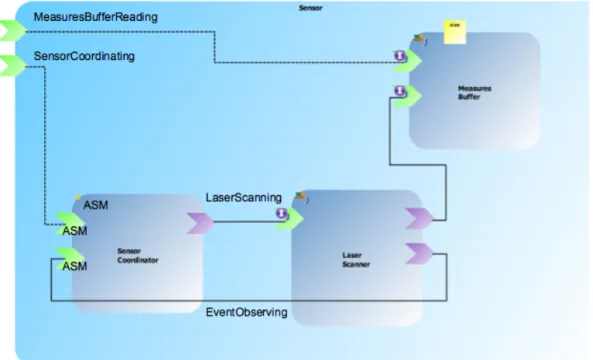
IV. THEUSECASE IMPLEMENTATION
The scenario presented above was implemented in SCA and ASM. Figure 10 illustrates the SCA Sensor Composite, which represents the sensor component defined in figure 6. The clients are not present in this diagram, but they can interact with the Sensor Coordinator and with the Measures Buffer through the Services offered by the composite. In par-ticular a client could request a scan by means of the service “Sensor Coordinating” and could access the Measures Buffer by means of the service “Measures Buffer Reading”.
• Component 1: Measures Buffer
– Provided Services:
∗ Measure Buffer Writing: it is used for writing a measure on the buffer.
∗ Measure Buffer Reading: it is used for reading a measure from the buffer.
• Component 2: Laser Scanner – Provided Service:
∗ Laser Scanning: it is used for starting a scan. The scan operation provided by the service requires two parameters: from and numOfSteps.
– Required Service:
∗ Measure Buffer Writing.
• Component 3: Sensor Coordinator – Provided Services:
∗ Sensor Coordinating: it is used in order to re-quest a number of scans. The scan operation pro-vided by the service requires three parameters: from, numOfSteps, and numOfScans.
∗ Event Observing: it is used in order to notify the coordinator when the scan process starts and when it finishes.
– Required Service: ∗ Laser Scanning.
A. The component interfaces and the data structures The interfaces of the services and the used data structures are reported in the listing 9. To be noticed that the interfaces of the Sensor Coordinator are defined both in Java and ASM. We have the necessity of define this component interface also in Java because in this way the Java interpreter can recognize them and so we can call the Sensor Coordinator services from a component implemented in Java without syntax errors.
1 public interfaceMeasuresBufferReading{ 2
3 publicLaserScan getScan(); 4 }
5
6 public interfaceMeasuresBufferWriting{ 7
8 public voidwriteMeasure(LaserMeasure measure); 9 }
10
11 public interfaceLaserScanning{ 12
13 /**
Fig. 10. The Sensor Composite
15 * @param numOfSteps: number of steps of the scan */
16 @OneWay
17 public voidscan(intfrom,intnumOfSteps); 18 }
19
20 public interfaceSensorCoordinating{ 21
22 /**
23 * @param from: point from which the laser starts the scan
24 * @param numOfSteps: number of steps of the scan
25 * @param numOfScans: number of scans required */
26 @OneWay
27 public voidrequest(intfrom,intnumOfSteps,intnumOfScans); 28 }
Listing 9. The Java interfaces of the components
In order to manage the notification received from the Laser Scanner the Sensor Coordinator also implements the interface reported in the listing 10. So far it is used as a Service in order to simulate a callback, because the callbacks are not yet supported in the SCA-ASM Eclipse plugin. It will be used as a SCA Callback as soon as this further feature will be implemented and supported.
1 public interfaceEventObserving{ 2
3 /**
4 * @param event: it describe the type of event.
5 * For the laser scanner valid values are ”Ack” and ”Done”
6 */
7 public voidupdate(String event); 8 }
Listing 10. The Java EventObserving interface
The ASM definitions of the sensor coordinators provided interfaces are reported in the listing 11 using the AsmetaL notation. They are ASM modules containing only declara-tions of business agent types, declared in terms of subdo-mains of the predefined ASM Agent domain, and of business
functions, declared as parameterized ASM out functions.
1 //@Remotable 2 module SensorCoordinating 3 importSTDL/StandardLibrary 4 importSTDL/CommonBehavior 5 export * 6 7 signature:
8 // the domain defines the type of this agent
9 domain SensorCoordinating subsetof Agent 10 // out is a function that implements the provided service
11 out request: Prod(Agent,Integer,Integer,Integer) −> Rule 12 definitions: 13 14 15 //@Remotable 16 module EventObserving 17 importSTDL/StandardLibrary 18 importSTDL/CommonBehavior 19 export * 20 21 signature:
22 domain EventObserving subsetof Agent 23 out update: Prod(Agent,String) −> Rule 24 definitions:
Listing 11. ASM definition of the Sensor Coordinating interface
V. CONCLUSIONS
In this paper we have presented a case study regarding the coordination in the context of a robotics application. The case study was developed by using SCA and ASM and has demonstrated that the use of these frameworks, which are widespread in other domains, is feasible also in the robotics field.
The use of two different frameworks for modeling two different concerns (SCA for computation and ASM for coordination) improves the level of flexibility and reusability.
Thanks to this orthogonal separation, we were able to im-plement two different policies without modifying the imple-mentation of the services offered by the Laser Scanner. In the same way it is possible to modify the implementation of the Laser Scanner services without modifying the coordination state machine.
Moreover ASM allows automatic validation and verifica-tion of the correctness and reliability of single components taken in isolation. It also consents runtime monitoring of the components and self-adaptation.
These positive features, the results demonstrated through our case study, the level of maturity of these frameworks and their significant spread in other domains such as the web services, support and advocate our thesis according to which the integration of SCA and ASM promises good results also in the robotics field.
VI. ACKNOWLEDGMENTS
The authors would like to thank all the partners of the BRICS project for their valuable comments.
REFERENCES
[1] G.T. Heineman and W.T. Councill. Component-based software engi-neering: putting the pieces together, volume 17. Addison-Wesley USA, 2001.
[2] C. Szyperski, D. Gruntz, and S. Murer. Component software: beyond object-oriented programming. Addison-Wesley Professional, 2002. [3] M. Radestock and S. Eisenbach. Coordination in evolving systems.
In proceedings of the Int. Workshop on Trend in Distributed Systems: CORBA and Beyond, volume 1161, pages 162–176. Springer LNCS, 1996.
[4] R. Bischoff, T. Guhl, E. Prassler, W. Nowak, G. Kraetzschmar, H. Bruyninckx, P. Soetens, M. Haegele, A. Pott, P. Breedveld, J Broenink, D. Brugali, and N. Tomatis. BRICS - Best practice in robotics. In proceedings of the IFR International Symposium on Robotics (ISR 2010), 2010.
[5] OSOA - Service Component Architecture (SCA). http://www.osoa.org/. [6] E. Borger and R.F. Stark. Abstract State Machines: A method for
high-level system design and analysis, 2003.
[7] E. Riccobene and P. Scandurra. Specifying formal executable behavioral models for structural models of service-oriented components. In ACT4SOC 2010 (4th International Workshop on Architecture, Concepts and Technologies for Service Oriented Computing), 2010.
[8] The ASMETA toolset: an analysis toolset for ASMs, 2006. http://asmeta.sf.net/.
[9] E. Riccobene and P. Scandurra. An ASM-based executable formal model of service-oriented component interactions and orchestration. In Workshop on Behavioural Modelling Foundations and Application (BM-FA 2010), 2010.