3
Number
2019
Publication Year
2019-12-19T13:40:04Z
Acceptance in
OA@INAF
AAVS1 Hybrid Cable's assembly and testing procedure
Title
RUSTICELLI, SIMONE; SCHIAFFINO, MARCO; PERINI,
FEDERICO; MONARI, JADER
Authors
IRA Bologna
Affiliation of first
author
http://hdl.handle.net/20.500.12386/20461;
http://dx.doi.org/10.20371/INAF/TechRep/3
Handle
1
AAVS1 Hybrid Cable’s assembly and
testing procedure
Authors: Simone Rusticelli1, Marco Schiaffino1, Federico Perini1 and Jader Monari1
2
Summary
Figure summary ... 3
Introduction ... 4
Pyramid assembly ... 5
Hybrid cable verification procedure ... 12
Test description ... 15
Test result ... 17
Appendix A – Hybrid cable reworking ... 18
3
Figure summary
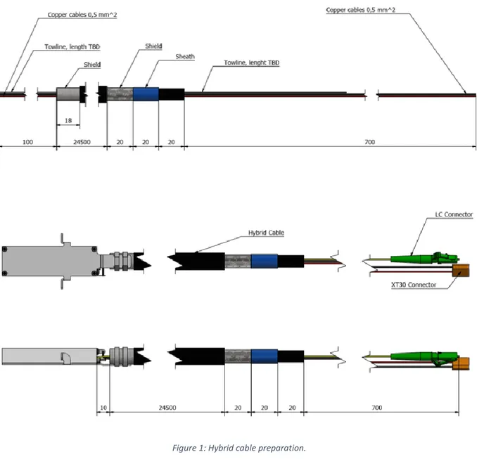
Figure 1: Hybrid cable preparation. ... 5
Figure 2: Trumpet insertion into the hybrid cable. ... 6
Figure 3: Threading the fiber into the hybrid cable. ... 7
Figure 4: FEM attachment and electrical wiring... 7
Figure 5: FEM correct position inside the trumpet assembly. ... 8
Figure 6: Screws position inside the trumpet. ... 9
Figure 7: Hybrid cable part’s dimensions. ... 10
Figure 8: Hybrid cables label numbering. ... 11
Figure 9: FEM numbering. ... 12
Figure 10: Label types. ... 12
Figure 11: Connector types. ... 13
Figure 12: FEM’s anchoring screws position inside the trumpet. ... 14
Figure 13: Bench test scheme. ... 15
Figure 14: Bench test (on the right) and HC production room (on the left). ... 16
Figure 15: Test result excel spreadsheet. ... 17
Figure 16: Measurement results. ... 17
Figure 17: Pyramid hat and LNA removing ... 18
Figure 18: Torx screws positions (top) and cup nut loosening direction ... 18
Figure 19: Optical transmitter displacement respect to the trumpet ... 19
Figure 20: TX module and hybrid cable alignment ... 19
Figure 21: Cable ties cutting ... 20
Figure 22: Outer jacket removing ... 20
Figure 23: Cable ties tightening ... 21
Figure 24: TX module fixing and orientation ... 21
Figure 25: Connections check ... 22
4
Introduction
This document describes the procedure whereby the 440 AAVS1 (Aperture Array Verification System) FEM were reworked by Lightech s.r.l. to be compatible with the pyramid assembly created by UCAM. Then there is a description of the reworking verification and the final testing procedure of the HC (Hybrid Cables).
5
Pyramid assembly
After the receiver testing, following the procedure described in IRA506-17, the FEM (Front End Module) were reworked in Lightech. Below there is the trumpet assembly procedure steps:
1. Preparation of the HC as depicted in Figure 1.
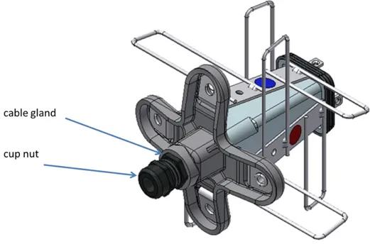
6 2. Make sure that the cable gland is fixed to the trumpet body and loosen the cup nut as in the figure
below.
3. Insert the hybrid cable inside the trumpet, from the FEM side (as shown in Figure 2Errore. L'origine
riferimento non è stata trovata.).
Figure 2: Trumpet insertion into the hybrid cable.
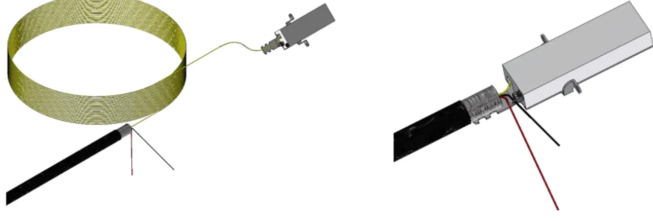
7 5. Cut the LC/APC optical connector and pull the fiber inside the hybrid cable from the FEM’s opposite
side, since to have 10mm between the hybrid cable to the module.
Figure 3: Threading the fiber into the hybrid cable.
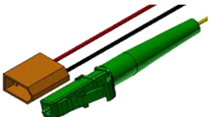
6. Fix the module to the hybrid cable with two plastic cable ties. Make sure there is a good contact between the cable armor and the FEM cover. Then cut and connect the copper cables to the feed trough and the tab, as shown in Figure 4.
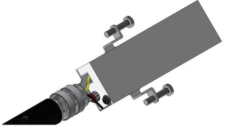
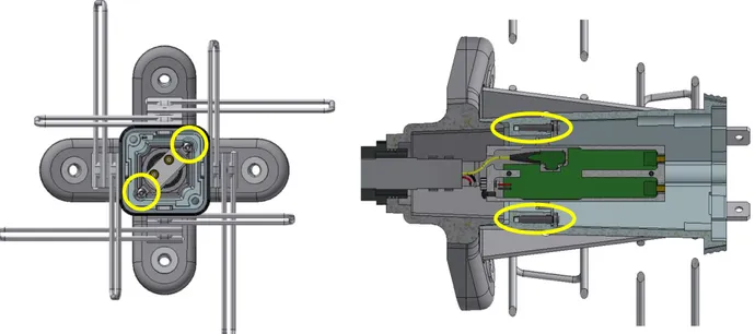
8 7. Place the two screws in order to simplify the connection of the module inside the trumpet, as shown
in the figure below.
8. Insert the FEM inside the trumpet with the orientation explained in Figure 5 (the cover must be in front of the blue dot, and opposite to the red dot).
9 9. Tighten the two screws with T10 screwdriver to fix the FEM as shown in Figure 6.
Figure 6: Screws position inside the trumpet.
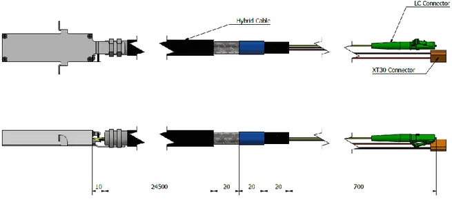
10 11. Make sure that the different hybrid cable lengths are respected as shown in Figure 7.
Figure 7: Hybrid cable part’s dimensions.
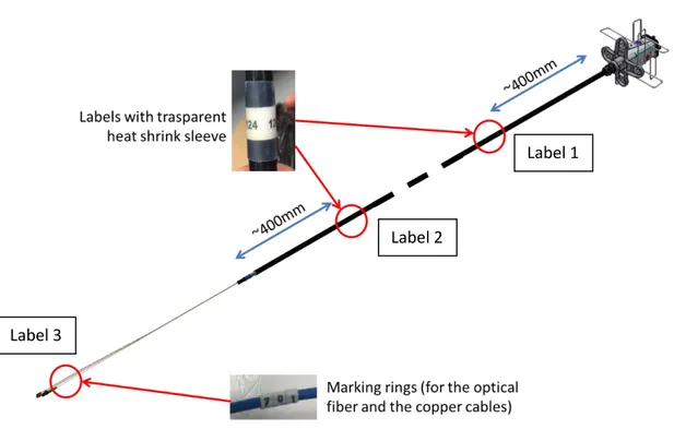
11 13. Put the labels with the serial numbers, in the positions shown in Figure 8.
Figure 8: Hybrid cables label numbering.
Label 1
Label 2
12
Hybrid cable verification procedure
After the cable preparation and the trumpet assembly and before testing, there is a verification phase in which are made some checks on labelling, tightening and FEM orientation correctness.
Below there is the list of the check made before the opto-electrical test:
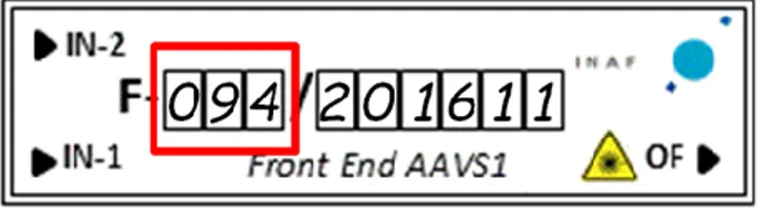
1. Labelling check: verification of the presence of the three labels on the HC showed in Figure 8 and matching the number with the FEM label (three digits in the red box in the Figure 9).
Figure 9: FEM numbering.
2. Labelling type: indicate whether the self-laminating style labeling (label 1, 2 and 3) and / or the RW175 sheath (label 1 and / or 2) + marking rings (label 3).
Laminating, label 1 and 2 Laminating, label 3
Sheath RW175, label 1 e 2
Marking rings, label 3
13 3. Connectors check: connector header check (electrical XT30 male and optical LC/APC) as in Figure 11.
Figure 11: Connector types.
4. FEM orientation: verify the correct orientation of the optical module. The lid should be opposite to the RED sticker and facing the BLUE sticker.
FEM lid
Red sticker
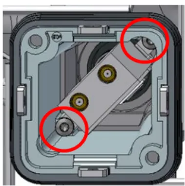
14 5. Tightening screws: verify the correct tightening of the screws indicated by the red circles in Figure
12.
Figure 12: FEM’s anchoring screws position inside the trumpet.
6. Cable gland tightening: check the tightening of the cable gland body on the trumpet and tightening the cable gland head on the HC (the HC must not rotate over the trumpet).
15
Test description
Firstly, the test consists in verifying the correctness of the assembly following the procedure listed below: 1. FEM orientation;
2. Cable labelling;
3. Optical (LC/APC) and electrical (XT30) connectors check; 4. Screws tightening;
5. Cable gland tightening.
Finally, if all the above points are met, measurements continue cleaning optical connectors and doing the following tests:
6. DC current consumption; 7. Optical power.
Point 7 consist in evaluating the optical power emitted downstream the hybrid cable at two different wavelengths (1270 and 1330nm) using a CWDM splitter and two optical power meters Thorlabs PM20C. These values were compared to those measured during RX tests done before the hybrid cable reworking and some assumptions have been made to determine whether assembly problems have occurred (Fail) or not (Pass).
16
17
Test result
After the measurement, was created a Microsoft Excel spreadsheet containing all the collected data and comparing them with the DC power consumption and optical power measurements done previously with the analog chain receiver tests. Below there is a screenshot of the spreadsheet produced.
Figure 15: Test result excel spreadsheet.
From the measurements results could be noticed that optical power is reduced, and this is due to fiber stress and joints during HC reworking. Sometimes it was found that optical power was increased probably because when the measurement had previously been made the connector could have been dirty or not well made. DC current could change because probably of the different temperature conditions and different time between the power on and the measurement, if compared to the measurements done before the reworking, which can cause an increase of consumption due to the thermalization of the internal components (i.e. gain block, laser diode). If the optical power and DC current consumption deviation from the pre-HC reworking measurements was reasonably limited (within a few tenths of optical dB and some mA) the test was considered Passed otherwise was Fail.
18
Appendix A – Hybrid cable reworking
In order to avoid floating grounds that could cause oscillation problems, has been improved the electrical connection between the metal box of the transmitter module and the hybrid cable armor. In the next paragraph will be described the operations necessary to carry out this modification.
Procedure
1. Remove the trumpet hat unscrewing the two plastic screws. Remove the two LNA boards from the pyramid assembly unscrewing the four torx socket countersunk head cap screws and two SMA connectors.
Figure 17: Pyramid hat and LNA removing.
2. Unscrew the two torx socket pan head tapping screws that fix the optical transmitter to the trumpet body (a torx screwdriver is recommended) and then loose the cup nut of the cable gland.
19 3. Push the transmitter out of the trumpet by acting on the cable 400 mm is enough.
Figure 19: Optical transmitter displacement respect to the trumpet.
4. Tight the transmitter module and the hybrid cable in two aligned clamps. The module and the cable must be well aligned.
20 5. Cut the two cable ties. Make sure that the hybrid cable doesn’t rotate in the clamp.
Figure 21: Cable ties cutting.
6. With a cutter remove the outer jacket of the hybrid cable close to the module cover, as indicated in the pictures. Be careful about the cover integrity.
21 7. Tight two cable ties to connect the module to the hybrid cable. After that is possible to remove the
assembly from the two clamps. Check if there are any short between the power lines.
Figure 23: Cable ties tightening.
8. Place the two torx socket pan head tapping screws as shown in the figure, to simplify the connection of the module inside the trumpet. After that, by pulling the hybrid cable, insert the transmitter module into the trumpet and fix it screwing the two torx socket pan head tapping screws. There are two possible orientations of the module inside the trumpet. The right one is with the FE label faced towards the red dot and the FE cover to the blue dot. Then tight the cable gland nut.
22 9. Check the connections of the coaxial cables with the MCX connectors of the FE module.
Figure 25: Connections check.
10. Re-install the two LNA boards and the trumpet hat.