Fault Dynamics Research Group, Geology Department, Royal Holloway, University of London Egham, SURREY, TW20 0EX, UK. Amilibia E-mail: [email protected] McClay E-mail: [email protected]
Departament de Geodinàmica i Geofísica, Facultat de Geologia, Universitat de Barcelona Martí i Franquès, s/n, 08028 Barcelona, Spain.
Analogue Modelling of Inverted Oblique Rift Systems
The geometric evolution of brittle fault systems in inverted oblique and offset rift systems has been simulated using scaled sandbox analogue models. Dry fine-grained quartz sand was used to represent the brittle upper crust. Extensional faults geometries in the models were governed by the geometry and orientation of a stretch-ing zone at the base of the models. Oblique rift models were characterized by segmented en-echelon border fault systems trending parallel to the rift axis and the underlying zone of basement stretching. Offset rift models promoted highly-segmented border faults as well as offset sub-basins within the rift. In both types of models, intra-rift fault arrays were oriented sub-perpendicular to the extension direction. Inversion of the oblique and offset extensional models was achieved by horizontal shortening. This resulted in partial inversion of the border and intra-rift faults as well as the formation of new reverse faults. The geometries, distribution, orientations and number of these new reverse faults were strongly controlled by the earlier-formed fault extensional architec-tures. At the margins of the rift zone, shortening was mainly accommodated by partial inversion of the border faults together with the formation of hanging-wall bypass faults and footwall shortcut thrusts. Inversion of the offset rift models produced reactivation of the extensional accommodation zones as soft-linked transfer zones between new thrust faults. The analogue model results have been compared with natural inversion structures in the Atlas Mountains of Morocco and the Ukrainian Donbas fold belt. The analogue modelling results suggest that the High Atlas formed as the result of oblique inversion of an oblique rift system, and the contractional structures in the Ukranian Donbas belt were generated by partial inversion of the earlier-formed Donbas exten-sional graben via two major newly developed short-cuts that uplifted and exhumed the basin.
Analogue modelling. Oblique and offset rifts. Tectonic inversion. Atlas Mountains. Donbas Fold belt.
INTRODUCTION
Many intracontinental rift basins have been subjected to post-rift contraction such that the original extensional faults were reactivated and inverted producing uplift, anticlinal structures and fold and thrust belts. These include the
intra-continental inverted basins in north Africa (the Atlas Moun-tains of Morocco and Algeria, Guiraud, 1998; Djebbar, 2001), as well as inversion anticlines on the NW European margin (the Central Graben of the Northen Sea, Bartholomew et al., 1993), the southern North Sea (Oud-mayer and Dejager, 1993) and the Broad Fourteens basin G e o l o g i c a A c t a , Vo l . 3 , N º 3 , 2 0 0 5 , 2 5 1 - 2 7 1
A v a i l a b l e o n l i n e a t w w w. g e o l o g i c a - a c t a . c o m
KEYWORDS
A B S T R A C T
A. AMILIBIA K.R. McCLAY F. SÀBAT J.A. MUÑOZ and E. ROCA 1 1 2 2 2
1
(Brun and Nalpas, 1996). On the other hand, many well-known mountain ranges such as the Pyrenees (Vergés and García-Senz, 2001), Iberian Range (Salas et al., 2001; Guimerà et al., 1995), Central Andes (Amilibia, 2002; Giambiagi et al., 2003) as well as the Ukrainian Donbas fold belt (Saintot et al., 2003), show structural geometries that are clearly controlled by pre-existing extensional structures that were reactivated during the subsequent contraction.
Scaled sandbox analogue models has been successfully used for many years to simulate the kinematics and geome-tries of brittle extensional and contractional deformation in the upper crust (Withjack and Jamison, 1986; Koopman et al., 1987; McClay and Ellis, 1987; Mulugeta and Koyi, 1987; Vendeville et al., 1987; Serra and Nelson, 1989; Col-letta et al., 1991; Tron and Brun, 1991; Buchanan and McClay, 1992; Liu et al., 1992; Brun and Tron, 1993; Lemon and Mahmood, 1994; Storti and McClay, 1995; McClay, 1995; McClay and White, 1995; Withjack et al., 1995; Dooley et al., 1999). In this paper we have used
sand-box modelling to investigate the inversion of oblique and off-set rift systems in order to develop models showing how pre-existing extensional fault systems control the development of later contractional structures in inversion terranes. As in the models presented by Panien et al. (2005), both the hanging wall and the footwall are free to deform in our experiments.
ANALOGUE MODELLING Experimental Method
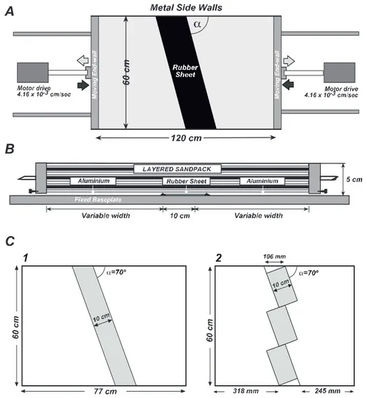
The experimental method follow that described by McClay and Ellis (1987) and used in more recent works such as Dooley (1994), Buchanan and McClay (1992), McClay and White (1995), McClay et al., (2002) and McClay et al., (2004, in press). The experiments were car-ried out in a deformation rig 80-120 cm long, 60 cm wide and 7.5 cm deep (Figs. 1A and 1B). The initial length of the models depended upon the obliquity of the basal zone
FIGURE 1 Analogue modelling rig. A) Plan view showing base-plate orientation with respect to the extension direction. B) Cross-section view of
deformation rig showing the layered sand pack location. C) Base-plate geometries used in this study: (A) 60ºoblique rift; (B) en-echelon
Analogue modelling of inverted rift
A . A M I L I B I A e t a l .
of stretching (Fig. 1C). The models were constructed on top of a basal detachment formed by 10 cm wide rubber sheet fixed between two rigid aluminium end sheets or plates, and consisted of a 5.0 cm thick-layered sandpack formed by mechanically sieving 4 mm thick layers of white and coloured dry quartz sand (Fig. 1B). Deforma-tion was achieved by moving one or both of the end walls with a motor-driven worm screw at a constant
displace-ment rate of 4.16 x 10⁻³ cm s-1. By changing the shape
and orientation of the rubber sheet, the initial graben ori-entation was varied. Offset rift models were produced by making offsets in the rubber sheet at the base of the mod-els (Fig. 1C-2). These experiments produced strongly seg-mented rift models in which depocenters were separated by complex accommodation zones of interlinked faults without the development of hard-linked strike-slip trans-fer faults (McClay et al., 2002).
The dry quartz sand used in the experiments has a grain size of 90-100 mm (for at least 90% of the grains). The mechanical properties of quartz sand show a linear
Navier-Coulomb behaviour with a friction angle of 31º
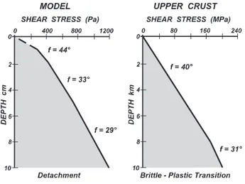
(McClay, 1990a). The models described in this paper are scaled such that 1.0 cm in the model simulates brittle deformation of a sedimentary sequence between 100 m to 1 km thick in the upper crust (Fig. 2) (McClay, 1990b).
The models were extended and shortened to a maxi-mum of 7.5 cm in 0.5 cm increments, and the top surfaces were recorded using digital photography. After each 2.0 cm of extensional deformation, the accommodation space generated by the extension was filled with alternating lay-ers of white and red sand (light grey and white in B/W pictures), thereby simulating syn-rift sedimentation that kept pace with subsidence and thus preserving the normal faults scarps from gravitational collapse. At the end of
extension a post-rift layer of green (dark grey in B/W pic-tures) sand was added prior to inversion. Frictional drag along the metallic sidewalls of the apparatus resulted in slightly curved surface fault traces near the edges of the models. Completed models were impregnated, serially sectioned vertically, and photographed in order to deter-mine the 3D structure of the models.
Model Description
Fourteen experiments on oblique and segmented rifts were carried out in this research programme. Two base plate geometries were used, a) 70º oblique rift and b) en-echelon segmented 70º oblique rift (Fig. 1C). For each base-plate geometry the rift stage and inversion models were repeated to ensure reproducibility. Representative experiments for each system are described in detail below.
Model 1 - Asymmetric 70º Oblique Half-graben System
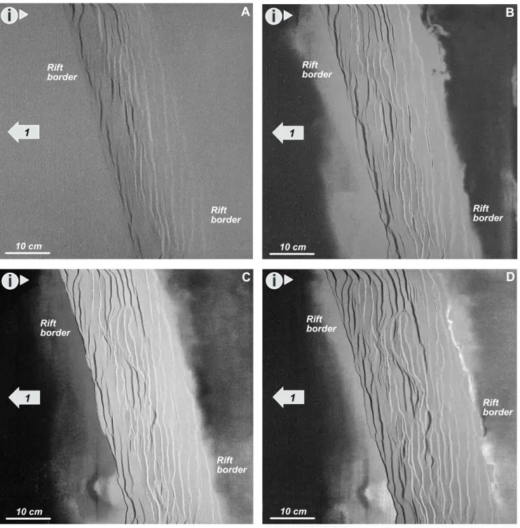
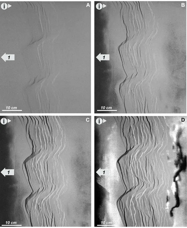
The model 1 deformed by asymmetric stretching of the layered sandpack above the basal rubber sheet. This was achieved by moving the left hand end wall of the apparatus whilst keeping the right hand end wall fixed. Figure 3 shows the sequential development of the model from 2.0 to 7.5 cm of extension. The first increments of extension produced slight subsidence above the stretched basal rubber sheet and thus defined the rift zone. After 2.0 cm of extension the fundamental architecture of the rift system had been established and faults were well devel-oped at the surface of the model (Fig. 3A). Arrays of small faults that were offset in an en-echelon fashion developed at the rift margins. These fault arrays were better developed along the left hand border fault system. With further extension, well-developed border faults formed from the along-strike linkage of the previous smaller en-echelon faults. Linkage between individual faults was accommodated by breached relay ramps. In the rift interior, left-dipping antithetic faults were developed. These intra-rift faults were shorter than the border faults, straight, and formed perpendicular to the extension direction.
At this stage (after 3.5 cm, Fig. 3B) the left hand rift border consisted of a well-developed array of slightly en-echelon linked extensional faults whereas the right hand rift border consisted of a segmented fault system. Exten-sion in the rift interior was clearly controlled by extenExten-sion direction intra-rift perpendicular fault arrays. The oblique rift system was strongly asymmetric with predominantly left-dipping domino faults within the centre of the model. Continued extension resulted in increased displacement on the major faults and upward propagation through the syn-kinematic sand layers. The smaller fault arrays that developed at the top of the model during the earlier stages of extension did not propagate upwards and are not observed on the top surface of the model at this stage.
FIGURE 2 Shear stress/depth plots for modelling material and for the upper crust (Byerlee law, 1978). The parameters in the models are scaled such that they simulate brittle deformation of sedimentary rocks in the upper crust.
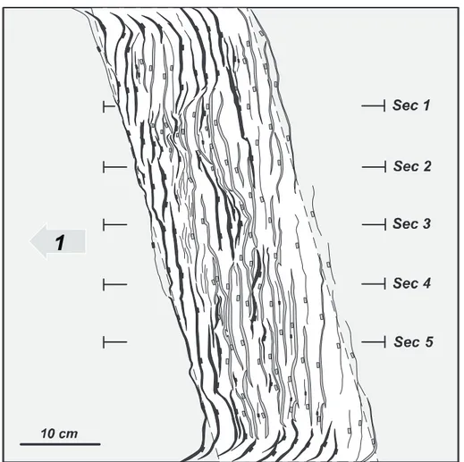
The final model, after 7.5 cm extension consisted of a well-developed oblique rift system with a linked and through-going left-hand border fault system, and dominant-ly left-dipping intra-rift fault arrays. Relay ramps, splays and kinks along the surface traces of individual faults indi-cated positions of fault linkage (Figs. 3D and 4).
Serial cross-sections parallel to the extension direc-tion illustrate an asymmetric rift system (Fig. 5). Secdirec-tion
5 cuts through the most asymmetric part of the rift sys-tem. This section shows a steep, planar right-dipping master fault on the left border of the model, with a series of antithetic left dipping normal faults within the rift. The intra rift faults had gentle dips compared with those located near the rift borders due to progressive rotation. The other cross-sections also show an asymmetric rift system diffused by flips in the vergence of the inner-faults arrays.
FIGURE 3 Analogue model 1= 70ºOblique Half-Graben system. Extension direction to the left as shown by the arrow, illumination is from the left. A) Overhead view of the analogue model after 2 cm extension. B) Overhead view of the analogue model after 3.5 cm extension. C) Overhead view of the analogue model after 5.5 cm extension. D) Overhead view of the analogue model final stage after 7.5 cm extension.
Model 2 - 70º Oblique En-echelon Half-Graben System
Model 2 was a 70º oblique extension experiment with two offsets the 70º oblique zone of stretching at the basal plate (Fig. 1C). The offsets are perpendicular to the rift axis and oblique to the extension direction. Asymmetric extension was achieved by moving the left hand end wall of the apparatus whilst keeping the right hand end wall fixed.
During the early stages of the model, three en-echelon basins were clearly defined trending obliquely to the extension direction. These newly developed sub-basins were delimited by two major depressions aligned with the basal offsets (Fig. 6A). Rift border faults as well as intra-rift faults were generated at the same time. Both sets of faults formed parallel to the oblique zone of stretching at the base of the model. The faults bend to parallelism with the rift offsets where they reach the basal offsets, linking to form major steeper obliquely trending faults. These faults control obliquely oriented depositional lows located above the basal offsets.
With increased extension (after 3.0 cm), all the faults defining the different half-graben systems bend to the left to reach a pseudo-parallelism with the oblique offset
Analogue modelling of inverted rift
A . A M I L I B I A e t a l .
FIGURE 4 Line diagram interpretation of the surface fault pattern at the end of extension. The white box marks the stret-ched rubber sheet at the base of the model that controls the rift area. Dark bands are faults dipping to the right and light bands are faults dipping to the left. Positions of Fig. 5 serial sections are indicated.
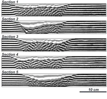
FIGURE 5 Serial sections cut parallel to the extension direction through analogue model 1= 70º Oblique Half-Graben system. Syn-kinematic strata are the pale grey and white layers infilling the upper part of the half-graben system whereas the pre-kinematic strata are black and white layers. This sections show the Half-graben geometry where many of the faults right of the rift border master fault are antit-hetic faults dipping towards the left. The depocenter is located closer to the left margin of the rift.
zones describing the accommodation zones between indi-vidual half-grabens basins (Figs. 6B and 6C). These accommodation zones were defined as low-relief accom-modation zones by McClay et al. (2002) and consisted of opposite-polarity faults arrays that show strong rotation into the accommodation zone and generated composite accommodation zones oblique to the extension vector
(Figs. 6C and 7). These accommodation zones are charac-terized by grabens that crosscut the basement offset and are bounded by the rotated tips of conjugate-fault sets. Newly formed minor inner-faults developed perpendicu-lar to the extension direction. The fundamental fault pat-tern did not change during the subsequent stages of exten-sion (Figs. 6C and 6D).
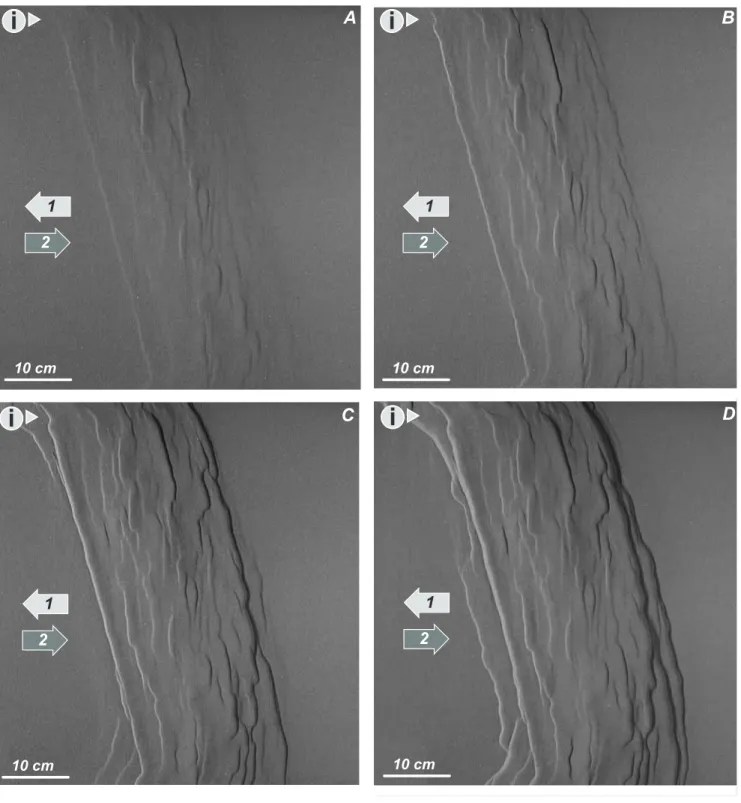
FIGURE 6 Analogue model 2= en-echelon Half-Graben system. Extension direction to the left as shown by the arrow. Illumination is from the left. A) Overhead view of the analogue model after 1.5 cm extension. B) Overhead view of the analogue model after 3 cm extension. C) Overhead view of the analogue model after 4 cm extension. D) Overhead view of the analogue model final stage after 7.5 cm extension.
Analogue modelling of inverted rift
A . A M I L I B I A e t a l .
At the end of the experiment at 7.5 cm extension (Figs 6D and 7) the model consisted of three well-defined graben systems that were offset in an en-echelon distribu-tion manner and linked by two major obliquely trending accommodation zones. The faults defining the individual graben systems were parallel to the rift axes and oblique to the extension direction. The faults that defined the accommodation zones were oblique to the basal offsets as well as to the extension direction. These faults controlled the deeper depocentres of the rift. The offset rift models generated excellent examples of segmented dip domains. The faults vergence changed when crossing the accom-modation zones (Fig. 7).
Figure 8 shows cross-sections across the sub-basins and accommodation zones. Sections 1, 3 and 4 cut across two of the well-defined sub-basins (Fig. 7). All of the cross-sections show symmetric graben systems, clearly defined by syn-kinematic sequence. Sections 5 and 2 cut the model across the accommodation zones between sub-basins. These cross-sections show well-defined left-ver-gent half-graben systems that control the deeper depocen-tres of the model.
FIGURE 7 Analogue model 2= en-eche-lon Half-Graben system. Line diagram interpretation of the surface fault pattern at the end of extension. The whites boxes mark the stretched rubber sheet at the base of the model that controls the rift area. Dark bands are faults dip-ping to the right and light bands are faults dipping to the left. Positions of Fig. 8 serial sections are indicated.
FIGURE 8 Serial sections cut parallel to the extension direction through analogue model 2= en-echelon Half-Graben system. Syn-kinematic strata are the pale grey and white layers infilling the upper part of the half-graben system whereas the pre-kinematic strata are black and white layers.
Inversion Models
Model 3 - Inverted 70º Oblique Half-graben System In this experiment the same base-plate designed for model 1 was used. At the end of the extensional phase the
fault systems were near identical to those in the model 1 described above. The rift borders were defined by linked en-echelon extensional faults trending 70º oblique to the extension direction. The intra-rift faults formed domino fault arrays trending at high angles to the extension
direc-FIGURE 9 Analogue model 3= Inverted 70º Oblique Half-Graben system. Extension direction to the left and compression direction to the right as shown by the arrows. Illumination is from the left. A) Overhead view of the analogue model after 2 cm of asymmetric shortening. B) Overhead view of the analogue model after 3 cm of asymmetric shortening. C) Overhead view of the analogue model after 5 cm of asymmetric shortening. D) Overhead view of the analogue model final stage after 7.5 cm of asymmetric shortening.
tion. After 7.5 cm of extension, a 4 mm thick, post-rift marker was added, and the model was shortened by mov-ing the left-hand wall back to the right. This produced compression and inversion in the central part of the model.
At the beginning of the inversion phase, small reverse faults together with their associated hanging-wall folds formed in the central part of the model. These faults were located in the inner part of the pre-existing rift system and trended nearly perpendicular to the shortening direction. The obliquely trending, steep rift border faults were par-tially inverted as reverse faults (Figs. 9A and 9B). With increased shortening (after 3.0 cm), individual segmented thrust faults propagated along strike and became linked. Two major reverse faults formed oblique to the shortening direction, following the pre-existing partially inverted rift border faults. These newly developed faults shortcut the extensional footwall, uplifted the basin and delimited the zone of deformation (Figs. 9C and 9D). By the end of the experiment, after 7.5 cm of shortening, the basin had been uplifted via major low angle reverse faults and internally deformed by partially inverted extensional faults. These internal reverse faults were perpendicular to the shorten-ing direction whereas the border faults were oblique to
Analogue modelling of inverted rift
A . A M I L I B I A e t a l .
FIGURE 10 Analogue model 3= Inverted 70º Oblique Half-Graben system. Line diagram interpretation of the surface fault pattern at the end of shortening. The white box marks the stretched rubber sheet at the base of the model that con-trols the deformation area. Black lines are reverse faults dipping to the left and grey lines are reverse faults dipping to the right. Positions of Fig. 11 serial sec-tions are indicated.
FIGURE 11 Serial sections cut parallel to the shortening direction through analogue model 3= Inverted 70º Oblique Half-Graben system. Syn-kinematic strata are the pale grey and white layers infilling the upper part of the half-graben system whereas the pre-kinematic strata are black and white layers. The Post-rift/Pre-inversion marker is the dark grey layer.
the shortening direction clearly reflecting the pre-existing extensional system geometry (Figs. 9D and 10).
Serial cross-sections cut through the final model par-allel to the shortening direction. These sections show how the inversion and uplift was focused on the pre-existing rift basin in the centre of the model. The rift border faults were only partially inverted with new shortcut reverse faults formed in their footwalls. Not all of the intra-rift extensional faults were reactivated and some were cut by new, low-angle reverse faults (Fig. 11). The basin was uplifted and ejected via two major reverse faults that shortcut the margins of the basin and produced a pop-up like geometry.
Model 4 - 70º Oblique Pure Contraction
In this model the basal plate was the same as that used in model 1 (Fig. 1C). The model simulated the deformation resulting from a phase of contraction oblique to a pre-exist-ing zone of weakness. To achieve a pure contraction model, the basal rubber sheet was pre-extended to a width of 17.5 cm before the pre-kinematic sandpack was added.
The first contractional structures formed, after 3 cm of shortening. These consisted of newly developed reverse faults that formed perpendicular to the shortening direc-tion and oblique to the axis of the basal zone of weakness (Fig. 12A). With increased shortening new reverse faults formed and linked with the pre-existing faults. These faults also were formed perpendicular to the shortening direction (Fig. 12A and 12C).
At 7.5 cm shortening, the deformation pattern consisted of shows a doubly-vergent reverse fault system trending oblique to the shortening direction (Figs. 12D and 13). The reverse faults were strongly perpendicular to the shortening direction. The major reverse faults on the right hand margin of the defor-mation zone were slightly (Fig. 13). Defordefor-mation was absorbed by a few major reverse faults and few internal reverse faults have been developed (Figs. 12D and 13). Model 5 - Inverted 70º Oblique En-echelon Half-graben System
In this experiment the same base plate was used as for model 2 described above (Fig. 1C). After 7.5 cm of exten-sion the rift was shortened by moving the left-hand wall back to the right, thus inverting the central part of the model. Previous to shortening, a 4 mm green sand layer has been added on top of the extensional final stage as a post-rift/pre-inversion marker layer.
After 2.0 cm of shortening the first compression struc-tures formed. These strucstruc-tures followed the pre-existing extensional fault setting (Fig. 14A). As the shortening was
increased these early marginal reverse faults linked to form a continuous border fault, reactivating the extensional accom-modation zone as a lateral ramps that connected the inverted margins (Figs. 14B and 14C). The majority of the internal reverse faults that formed were smaller and developed sub-parallel to the rift axis, except for those that formed above the accommodation zones. The high number of internal faults, compared with the pure-contraction model, as well as their parallelism with the inner extensional faults, helps us to interpret them as mainly inverted normal faults.
After 6.0 cm of shortening, new reverse border faults formed perpendicular to the shortening direction. These were low angle reverse faults that shortcut the footwall of the extensional faults, uplifting the entire basin (Fig. 14C). Some minor newly formed internal faults also had traces trending perpendicular to the shortening direction.
At the end of the experiment, after 7.5 cm of shortening, a complex array of reverse faults had formed at the margins of the uplifted rift basin in the central part of the model (Figs. 14D and 15). The earlier-formed intra-rift faults had become partially inverted and the fault segments were large-ly perpendicular to the contraction direction whereas the rift border had inverted to form an array of kinked and overlap-ping reverse faults controlled by the orientation and position of the rift margins that formed during the extensional phase (Fig. 6D vs. Fig. 14D and Fig. 7 vs. Fig. 15).
Figure 16 shows serial cross-sections that cut through the model, parallel to the shortening direction. These cross-sections show how the inversion and uplift was focused on the pre-existing rift basins in the central part of the model. The rift border faults were only partially inverted. Instead new shortcut reverse faults formed in their footwalls. These footwall shortcuts are more evident in the cross sections that cut through the deeper exten-sional depocentres located above the offsets rift. The cross-sections also show how some of the internal rift faults were partially reactivated and inverted, and some were cut by new, low angle thrust faults that nucleated in the centre of the compressional zone. These by-pass thrusts transported and uplifted the syn-extension sequence to the externals parts of the rift producing sub-tractive contacts that juxtaposed younger rocks on top of older pre-extensional rocks (Fig. 16, Section 5).
DISCUSSION
Analogue Modelling
Modelling Results and Comparisons
The new analogue models presented here have yielded very interesting results that allow the influence
Analogue modelling of inverted rift
A . A M I L I B I A e t a l .
of pre-existing structures on a later phase of shortening to be qualitatively assessed. The results presented in this paper also show strong affinities with the results of previous works (Eisenstadt and Withjack, 1995; Dubois et al., 2002; Brun and Nalpas, 1996; Panien et al., 2005).
The extensional models produced linked rift border fault systems, where the orientation of the faults was con-trolled by the geometry of the underlying basal rubber sheet (McClay et al., 2004; McClay and White, 1995) (Figs. 3 and 4). Oblique rift models developed asymmet-ric rift systems where the majority of the intra-rift faults
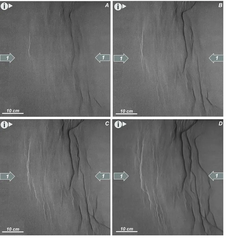
FIGURE 12 Analogue model 4= 70º Oblique Compression. Compression comes from both sides as shown by the arrows. Illumination is from the left. A) Overhead view of the analogue model after 3.5 cm of symmetric shortening. B) Overhead view of the analogue model after 4.5 cm of symmetric shortening. C) Overhead view of the analogue model after 5.5 cm of symmetric shortening. D) Overhead view of the analogue model final stage after 7.5 cm of symmetric shortening.
dipped towards the left hand moveable end-wall. These models also showed strongly segmented rift border faults trending closely parallel to the rift axis, whereas the intra-rift faults were oriented sub-perpendicular to the exten-sion direction. The oblique model displayed significant structural variations along strike, such as fault polarity reversals that resulted in the development of intra-rift sub-basins. Relay ramps were also formed between overlap-ping extensional fault segments.
Analogue models of segmented offset oblique rifts produced distinctly different fault patterns compared with those with no offsets. Sub-basins developed whose faults displayed dip polarity changes above the hard-linked transfer zone in the basement. The presence of the basal offset in the rift zone did not produce a discrete transfer strike-slip fault in the cover during the extensional stage. Two types of soft-linked accommodation zones can be developed depending upon the increase or decrease of the initial rift axis length after the offset. In these experiments low-relief accommodation zones were generated (Figs. 6D and 7). These low-relief accommodation zones were generated above positive rift segmentation (where the segmentation increases the rift width). These zones con-sisted of oppositely dipping faults arrays that show strong rotation in to the accommodation zone and generated
composite transfer zones trending oblique to the exten-sion vector.
To investigate the influence of pre-existing zones of weakness on inversion geometries, we compared two mod-els shortened by the same amount. These were; a 100% inversion model (model 3) and a pure contractional model (model 4). Apart from the experiments of Eisenstadt and Withjack (1995), previous inversion analogue modelling publications (Dubois et al., 2002; Brun and Nalpas, 1996; Panien et al., 2005) did not undertake this comparsion to validate the influence of the earlier formed extensional structures during the subsequent contractional phase.
These simple comparisons reveal the strong control of the pre-existing extensional structures on the faults that developed during the later shortening phase (Figs. 9D and 12D). Plan view photographs of the pure contraction model show that shortening is mainly absorbed via dis-crete fault zones that developed on either side of the mod-el, striking perpendicular to the shortening direction. The obliquity of the basal rubber sheet controlled the location of the main structures but not their orientation (Fig. 13). In the inversion model-3 (Fig. 10), however, deformation was more distributed throughout the model due to the reactivation of normal faults and the formation of new
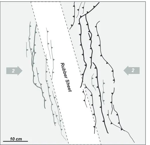
FIGURE 13 Analogue model 4= 70º Oblique Compression. Line diagram interpretation of the surface fault pattern at the end of shortening. The white box marks the stretched rubber sheet at the base of the model that controls the deformation area. Black lines are rever-se faults dipping to the left and grey lines are reverse faults dipping to the right.
reverse faults. Inversion of the rift models primarily resulted in uplift and inversion of the centre of the extend-ed area, forming symmetric bulges whose limits were controlled by the underlying basement geometries and extensional structures. The influence of the previous
extensional faults controlled the formation of border reverse faults trending parallel to the rift margins and oblique to the contraction vector in comparison with the perpendicular reverse faults developed in the pure con-traction model. These structures were partially inverted
Analogue modelling of inverted rift
A . A M I L I B I A e t a l .
FIGURE 14 Analogue model 5= Inverted en-echelon Half-Graben system. Extension direction to the left and compression direction to the right as shown by the arrows. Illumination is from the left. A) Overhead view of the analogue model after 2 cm of asymmetric shortening. B) Overhead view of the analogue model after 4 cm of asymmetric shortening. C) Overhead view of the analogue model after 6 cm of asymmetric shortening. D) Overhead view of the analogue model final stage after 7.5 cm of asymmetric shortening.
extensional border faults and newly formed low angle reverse faults that shortcut the footwalls of the extension-al faults and uplift the models forming a pop-up like structure (Figs. 10 and 11). Intra-rift faults were partially inverted and consisted of a set of small reverse faults in the internal part of the deformation zone, trending per-pendicular to the shortening direction. It is clear from a comparison of models 1 and 3 in Figs. 4 and 10 that the original extensional faults controlled the early distribution of shortening in the inversion models. These was also observed by Dubois et al. (2002), where reverse faults were oblique to the secondary tectonic stress state but parallel to the primary normal faults, suggesting that geometries inherited from previous tectonic phases influ-ence the creation of new faults and their slip direction. Eisenstadt and Withjack (1995) arrived at the same con-clusions from the analysis of clay models.
Shortening of the rifted area in the models is first accommodated by the upward bulging of the basin regardless of the composition of the fill or the graben ori-entation as Panien et al. (2005) suggested. As the amount of shortening increase the formed reverse faults propagate along-strike and link with the nearest reverse fault regard-less of the underlying extensional faults. This explains the decrease in the number of individual faults at the end of
FIGURE 15 Analogue model 5= Inverted en-echelon Half-Graben system. Line diagram inter-pretation of the surface fault pattern at the end of shortening. The white boxes mark the stretched rubber sheet at the base of the model that con-trols the deformation area. Black lines are rever-se faults dipping to the left and grey lines are reverse faults dipping to the right. Positions of Fig. 16 serial sections are indicated.
FIGURE 16 Serial sections cut parallel to the shortening direction through analogue model 5= Inverted en-echelon Half-Graben system. Syn-kinematic strata are the pale grey and white layers infilling the upper part of the half-graben system whereas the pre-kinematic strata are black and white layers. The Post-rift/Pre-inversion marker is the dark grey layer.
Analogue modelling of inverted rift
A . A M I L I B I A e t a l .
the contraction. The anomalously high number of con-tractional structures developed in the inner part of the deformation zone of the inversion model compared with the pure-contraction model reflected the strong influence of the previous extensional structures during the contrac-tional phase of deformation (Figs. 9D and 12D). Reverse faults show less changes in polarity along-strike in com-parison with the changes observed in the rift models, nev-ertheless the system shows a doubly-vergent geometry.
In the clay models of Eisenstadt and Withjack (1995), contractional reactivation of the main normal faults ceased between 50% and 100% inversion. Instead, low-angle thrust faults with small displacements accommodat-ed most of the shortening, deforming both the hanging-wall and foothanging-wall of the earlier extensional fault. These observations are coherent with our results shown in Figs. 9 and 11, where after 5.0 cm of shortening, the reactiva-tion of extensional structures ceased and new lower angle thrust faults uplifted and ejected the basin producing a pop-up like geometry.
The cross-sections through the well defined half-grabens also show how the master faults were partially inverted and later transported via lower angle, newly formed short-cut thrusts (Fig. 11, Section 2). The antithet-ic extensional faults on the other side of the graben were not reactivated. Instead, a by-pass thrust initiated in the weak basal zone, that ejected and transported the basin towards the right (Fig. 11, Section 3 and Fig. 16, Section 5). These observations were also described by Panien et al. (2005).
The inversion modelling results show how after 100% inversion, the majority of the reactivated normal faults have net extensional displacements. This analysis is inco-herent if we assume that the basin was 100% inverted. The problem is that the null-point analysis fails because shortening during inversion is partially accommodated by the newly formed reverse faults and reactivated secondary faults, and not only by inversion of the main normal faults. Although cross-sectional area is preserved in the models during inversion, uplift calculations also fail to predict the amounts of shortening because both the foot-wall and hanging foot-walls were elevated during inversion. Thus, the interpreted regional datum is too high and the measured amount of uplift above the regional datum is too low. This observation was also made by Eisenstadt and Withjack (1995). They demonstrated how such meth-ods will fail when trying to determine the amount of inversion in natural examples. Quantitative and qualitative methods will always underestimate the amount of short-ening that the area experienced.
In the inverted segmented oblique rift models, linkage between discrete reverse faults across the extensional
accommodation zones was accomplished by the oblique reactivation of 45º oblique extensional faults, above the basal offsets. These zones connected the reverse faults and accommodated the oblique slip component of move-ment (Figs. 14D and 15). Cross-sections through model 5 show how the faults striking 45º oblique to the shortening direction were reactivated during contraction (Figs. 7 and 16, Sections 2, 3 and 5). This is coherent with the conclu-sions presented by Brun and Nalpas (1996) where normal faults were only reactivated as oblique-slip faults if the angle between the shortening direction and the fault was smaller than 45º (Fig. 17). Nevertheless, no discrete tear-fault was developed in contrast with the oblique inversion model of Dubois (2002), where strike-slip faults trending parallel to the extensional master faults were developed during the contractional stage. These, probably developed due to the absence of a rubber sheet at the base of the model that transferred de deformation up to the sandpack. These results demonstrate how discrete extensional accommodation zones localise transfer zones as well as lateral ramps (when the accommodation zone connects sub-basins with different thicknesses) between reverse faults during a later contractional stage.
The gently dipping newly formed reverse faults shortcut the footwall of the half-graben border faults, uplifting and ejecting the graben in a pop-up like struc-ture (Fig. 16). The obliquity between the reverse faults
FIGURE 17 Inverted Half-graben Synoptic-3D model, across the accommodation zone between two of them. A) The final extension stage shows the accommodation zone between two half-grabens and the faults setting in these accommodation zones. B) The Inversion stage (after 100% Inversion) shows how the contractional structures reproduce the previous extensional setting and offsets the axial anti-cline along strike, using the accommodation zones as lateral ramps. External footwall shortcuts as well as internal inverted faults mainly absorbed the shortening.
trend and the shortening direction is due to the influ-ence of the pre-existing normal faults controlling the location and orientation of newly formed contractionl structures. The pre-existing weak planes, were used to nucleate new faults, instead of developing new weak zones perpendicular to de shortening direction. As soon as the shortening increased minor inner reverse fault were generated perpendicular to the shortening direction and parallel to the inner-rift extensional faults (Fig. 14). These faults are new by-pass reverse faults and partially inverted gently dipping normal faults (Figs. 5 and 7). Reactivation of normal faults during shortening in the models of Panien et al. (2005) is lim-ited and occurs along the main normal faults closest to the mobile wall. On the other hand, Brun and Nalpas (1996) suggested that in orthogonal shortening, reacti-vation of normal faults dipping at 60º is not possible in purely brittle systems. Our modelling results, as well as those of Dubois et al. (2002) demonstrate that this is not always the case.
To conclude, shortening is accommodated by struc-tures that initiated in zones that deform more easily. These zones of weakness are localized within the pre-existing extensional graben. The basal weak zone, formed by the rubber sheet at the base of the model is a first order zone of weakness. The extensional fault planes are small-er scale zones of weakness. On these planes, the grains of sand are less tightly packed over a width about 10 times the mean grain size.
Limitations of the model
The pre-determined fabric at the base of the experi-ments does not truly represent the anisotropy of natural basement fabrics. As Morley (1999) suggested, the sand itself should contain the pre-existing fabric before the deformation starts, something that is difficult to achieve without scaling problems in analogue modelling. Howev-er the base rubbHowev-er sheet control the strain distribution, which simulates a distributed area of extension.
We observed that some of the extensional faults were not reactivated during inversion. This can be related to the physical properties of the modelling materials. Fault reac-tivation can occur under stress levels lower than those necessary for create new faults (Sibson, 1995), because pre-existing faults are surfaces along which the cohesive strength and the friction coefficient are lower than those of intact rock (Anderson, 1951). The sand used in the modelling has a low cohesive strength, so there is little difference between the strength of faulted sand and the un-faulted sand. This insufficient contrast between faulted and un-faulted sand may make it easier to develop a new gently dipping reverse fault than to reactivate and rotate a pre-existing normal fault under contraction. Nevertheless,
in sandbox models during inversion, the faults commonly break along pre-existing fault planes. Along these planes the grain of the sand are less tightly packed, over a width about 10 times the mean grain size forming weak zones. These contrasting observations explain why fewer faults than expected become reactivated during inversion.
Natural Examples
3D Analogue models of oblique and segmented oblique rifts were run to provide templates for the inter-pretation of deformation structures in inverted intra-conti-nental rift systems and to investigate the control of the basement structures on rift architecture and inversion.
The scaled analogue models described in this paper are closely comparable with natural examples of inver-sion structures such as the Atlas Mountains of Morocco and Algeria and the Ukrainian Donbas fold belt. Although similarities between the geometries of the models and natural examples do not in themselves imply similar deformation mechanisms and evolutions, the fault styles, patterns, and populations strongly resemble each other.
Moroccan Middle Atlas
The Moroccan Atlas is an intra-continental mountain
belt that includes the N70ºE trending High Atlas and the
N45ºE trending Middle Atlas (Frizon de Lamotte et al.,
2004; Piqué et al., 2002). The obliquity between the Mid-dle Atlas structural grain and the shortening vector during the N-S Eocene Alpine contraction may be reflect the inversion of a previous oblique rift (arrows in Fig. 18A)(Guiraud, 1998; Beauchamp et al., 1996).
The Late Triassic-Early Liassic period was character-ized by major NW-SE extension, and the development of the NE-SW trending Atlasic rift, which extended from the Middle Atlas to the central High Atlas, parallel to the Atlantic rift bordered (Fig. 18). Brittle upper crust normal faults trend, were inherited from Pan-African and Variscan basement fabrics (Ait Brahim et al., 2002).
Inversion of the Mesozoic Atlasic rift took place dur-ing the Early Cretaceous (early Alpine phase), and the Paleogene (late Alpine phase) (Beauchamp et al., 1996; Gomez et al., 1998; Piqué et al., 2002), when most of the reverse faults and folds of the Atlas were formed (Ait Brahim et al., 2002). The axes of the inverted anticlines are centred over the axes of extensional half-grabens and trend oblique to the N-S shortening direction.
This structural pattern is directly analogous to the inverted oblique rift model 3 where both the internal faults and the border-faults developed oblique to the main
shortening direction, reflecting the previous extensional fault setting (Figs. 9D and 10).
The en-echelon, doubly-plunging fold geometries as well as its limited-strike extent typical in the Atlas Moun-tains of Morocco and Algeria, reflects the displacement variations along individual extensional faults, whereby displacement diminishes towards the fault tips (Djebbar, 2000).
The interpretation of seismic reflection profile MR22 across the western margin of Missour Basin shows an inverted Mesozoic fault (Fig. 19A). The normal fault was reactivated during the Paleogene contractional event, pro-ducing uplift of the syn-rift sequence. With increased shortening, the steeper upper part of the extensional fault
could not be inverted and a low angle thrust fault formed. This fault shortcuts the footwall of the exten-sional fault and transported the basin towards the north-west. This type of structure and its evolution is consis-tent with the results of the inversion experiments (Figs. 12 and 16), and shows how shortening is accommodated by new low-angle reverse faults that shortcut the foot-wall of the extensional basement when the fault is too steep to be reactivated.
Morocco High Atlas
Assuming that both branches of the original rift sys-tem (The Middle Atlas trending N45ºE and the High Atlas trending N70ºE) developed under the same NW-SE ten-sional stress field, neither can be a pure orthogonal rift. This observation helps to interpret the formation of the Morocco High Atlas thick-skinned fold and thrust belt as the result of an oblique inverted slightly oblique rift sys-tem during the Mesozoic. The structures interpreted in the cross-sections of Teixell et al. (2003) through the High Atlas and those of Frizon de Lamotte et al. (2004) in the Middle Atlas, show strong similarities with structures developed in model 3 (Figs. 19B and 11). These examples show how the rift basin was exhumed by two younger reverse faults, and that the internal faults underwent little reactivation or buckling. In map view, the western High Atlas shows internal structures trending oblique to the main border faults. This obliquity was inherited from the earlier oblique extensional setting, as shown by the ana-logue models. Nevertheless, in the High Atlas, case the heritage is masked by the existence of a detachment level
Analogue modelling of inverted rift
A . A M I L I B I A e t a l .
FIGURE 18 A) Morpho-structural units of the Atlas Mountains of Morocco. The rectangle marks the location of B SRTM DEM image. B) SRTM DEM image from Central Morocco. From north to south we observe: the rif and pre-rif thrust belts, the oblique striking Middle Atlas, the Missour basin and the High Atlas. The image also shows the location of the seismic line MR22 (Fig. 19).
at the base of the syn-rift sequence (Triassic Keuper salts). This ductile layer accommodated part of the obliq-uity and as such, this is only partially expressed in the upper sedimentary sequence. Unpublished analogue mod-els run by the authors reinforce this theory.
Donbas Fold belt
The Donbas fold belt is an uplifted and deformed part of the Pripyat-Dniepr-Donets basin, located in the south-western part of the East European platform in Ukraine (Fig. 20A), (Maystrenko et al., 2003; Saintot et al., 2003). It is considered to be an example of an inverted intracra-tonic rift basin. The Pripyat-Dniepr-Donets basin was formed as a result of an intracratonic rifting in Late Devonian-Carboniferous times. The Donbas fold belt is an uplifted and inverted part of this basin that resulted from at least two contractional phases that occurred dur-ing Late Triassic and Latest Cretaceous-Tertiary times.
The interpreted seismic profile across the Donbas thrust belt shows geometrical similarities with the ana-logue model cross-sections (Figs. 11, 16 and 20B). The
southern extensional border fault was partially inverted and later transported towards the south west by a new low-angle thrust fault that shortcut through the footwall of the extensional fault. This was described in the cross-sections through the inversion models. The south dip-ping antithetic faults were not reactivated and the exten-sional basin was uplifted and ejected to the northeast by a new developed by-pass thrust that nucleated in the weak lower crust.
CONCLUSIONS
In analogue models of oblique and segmented inverted rifts, the earlier formed extensional structures controlled the orientation, length, distribution and number of the contractional structures developed during the contraction-al phase.
Shortening during inversion is accommodated by the reactivated, oblique extensional structures and newly formed low-angle reverse fault that developed at the end of the contractional phase.
FIGURE 19 A) Interpretation of Line MR-22 (Beauchamp, 1996) through the NW margin of the Missour Basin. During the over imposed early Cretace-ous contractional stage the normal listric fault was partially inverted. With increased contraction a footwall shortcut was generated and the shorte-ning is accommodated by low angle inverted fault. B) Regional section across Morocco High Atlas after Teixell (2003).
The extensional accommodation zones that developed in the segmented rift models were reactivated as linkage zones between offset reverse faults during inversion. No evidence of tear-fault development was observed.
Quantitative and qualitative assessment of the magni-tude of inversion underestimates the amount of shorten-ing.
The presence of a potential detachment level in the syn-rift or post-rift sedimentary sequence masks the direct relationship between the extensional and contrac-tional structures(Morocco Atlas), nevertheless the nucle-ation of new contractional structures is controlled by the inversion of the basement extensional faults.
Low cohesive strength of the used sand, results in lim-ited reactivation of structures during inversion.
Obliquity between the reverse faults trend and the direction of shortening reflects the influence of the earli-er formed extensional structures. These structures con-trol the oblique trending of the contractional structures during inversion as shown in Morocco Middle Atlas Mountains.
ACKNOWLEDGEMENTS
We would like to thank the Fault Dynamics Group members for their support in the lab, Mike Craker for con-structing the deformation apparatus, Paul Whitehouse and Jose DeVera for constructive discussions and for impro-ving the English, and Tim Dooley for his sincere review of this paper. This work was supported by projects PB96-1002 and BTE2000-0571 of the Ministerio de Ciencia y Tecnologia of Spain.
Analogue modelling of inverted rift
A . A M I L I B I A e t a l .
FIGURE 20 Ukrainian Donbas fold belt Inversion example. A) Location map. B) Seismic line interpretation showing the inversion and exhumation of the Donbas Graben Basin (modified from Maystrenko et al., 2003).
REFERENCES
Amilibia, A., 2002. Inversión Tectónica en la Cordillera de Domeyko, andes del Norte de Chile. Doctoral thesis. Uni-versitat de Barcelona, 174 pp.
Anderson, E.M., 1951. The dynamics of faulting and dyke for-mation with applications to Britain. Olivier and Boyd (eds.). Edinburgh, 203pp.
Ait Brahim, L., Chotin, P., Hinaj, S., Abdelouafi, A., El Adraoui, A., Nakcha, C., Dhont, D., Charroud, M., Sossey Alaoui, F., Amrhar, M., Bouaza, A., Tabyaoui, H., Chaouni, A., 2002. Paleostress evolution in the Moroccan African margin from Triassic to Present. Tectonophysics, 357, 187-205.
Bartholomew, I.D., Peters, J.M., Powell, C.M., 1993. Regional structural evolution of the North Sea: oblique-slip and reactiva-tion of basement lineaments. In: Parker, J.R. (ed.). Petroleum Geology of Northwest Europe: Proceedings of the 4th
Confer-ence. London, Geological Society of London, 1109-1122. Beauchamp, W., Barazangi, M., Demnati, A., El Alji, M., 1996.
Intracontinental Rifting and Inversion: Missour Basin and Atlas Mountains, Morocco. American Association of Petro-leum Geologist Bulletin, 80(9), 1459-1482.
Brun, J-P., Tron, V., 1993. Development of the North Viking Graben: inferences from laboratory modelling. Sedimentary Geology, 86, 31-51.
Brun, J.P., Nalpas, T., 1996. Graben inversion in nature and experiments. Tectonics, 15, 677-687.
Buchanan, P.G., McClay, K.R., 1992. Experiments on basin inversion above reactivated domino faults. Marine and Petroleum Geology, 9, 486-500.
Byerlee, J.D., 1978. Friction of Rocks. Birkhauser Verlag, Basel, Pure and Applied Geophysics, 116.
Colletta, B., Letouzey, J., Pinedo, R., Ballard, J.F., Bale, P., 1991. Computerized X-ray tomography analysis of sandbox models: examples of thin skinned thrust systems. Geology, 19, 1063-1067.
Djebbar, T., 2001. Structural evolution of the Algerian Saharan Atlas. Doctoral thesis. Royal Holloway University of Lon-don, 373pp.
Dooley, T., 1994. Geometries and kinematics of strike-slip fault sys-tems: insights from physical modelling and field studies. Doctor-al thesis. RoyDoctor-al Holloway, University of London, 463 pp. Dooley, T., McClay, K.R., Bonora, M., 1999. 4D Evolution of
Segmented Strike-slip Fault Systems: Applications to NW Europe. In: Fleet, A.J., Boldy, S.A.R. (eds.). Proceedings of the 5thConference-Petroleum Geology of NW Europe.
Lon-don, Geological Society of LonLon-don, 215-225.
Dubois, A., Odonne, F., Massonnat, G., Lebourg, T., Fabre, R., 2002. Anallogue modelling of fault reactivation: tectonic inversion and oblique remobilisation of grabens. Journal of Structural Geology, 24, 1741-1752.
Eisenstadt, G., Withjack, M.O., 1995. Estimating inversion: Results from Clay models. In: Buchanan, J.G., Buchanan, P.G., (eds.). Basin Inversion. Geological society Special Publication, 88, 119-136.
Frizon de Lamotte, D., Crespo-Blanc, A., Saint-Bézar, B., Comas, M., Fernàndez, M., Zeyen, H., Ayarza, P., Robert-Charrue, C., Chalouan, A., Zizi, M., Teixell, A., Arboleya, M.L., Alvarez-Lobato, F., Julivert, M., Michard, A., 2004. TRANSMED Transect I. In: Cavazza, W., Roure, F., Spak-man, W., Stampfli, G.M., Ziegler, P.A. (eds.). The TRANSMED Atlas-The Mediterranean Region from Crust to Mantle. Berlin Heidelberg, Springer, 141 pp.
Giambiagi, L.B., Alvarez, P.P., Godoy, E., Ramos, V.A., 2003. The control of pre-existing extensional structures on the evolution of the southern sector of the Aconcagua fold and thrust belt, southern Andes. Tectonophysics, 369, 1-19. Gomez, F., Allmendinger, R., Barazangi, M., Er-Raji, A.,
Dah-mani., M., 1998. Crustal shortening and vertical strain parti-tioning in the Middle Atlas Mountains of Morocco. Tecton-ics, 17(4), 520-533.
Guimerà, J., Alonso, A., Mas, J.R., 1995. Inversion of an exten-sional-ramp basin by a newly formed thrust: The Cameros Basin (N. Spain). In: Buchanan, J.G., Buchanan, P.G. (eds.). Basin Inversion. Geological Society of London, Special Publication, 88, 433-453.
Guiraud, R., 1998. Mesozoic rifting and basin inversion along the northern African Tethyan margin: an overiew. In: Mac-Gregor, D.S., Moody, R.T.J., Clark-Lowes, D.D. (eds.). Petroleum Geology of North Africa, London, Geological Society, Special Publication, 132, 217-229.
Koopman, A., Speksnijder, A., Horsfield, W.T., 1987. Sandbox models studies of inversion Tectonics. Tectonophysics, 137, 379-388.
Lemon, N.M., Mahmood, T., 1994. Two and three dimen-sional analogue modelling of extendimen-sional faults systems with application to the North West Shelf, Western Aus-tralia. Australian Petroleum Exploration Association Journal, 34, 555-565.
Liu, H., McClay, K.R., Powell, D., 1992. Physical models of thrust wedges. In: McClay, K.R. (ed.). Thrust Tectonics. London, Chapman and Hall, 71-81.
Maystrenko, Yu., Stovba, S., Stephenson, R., Bayer, U., Meny-oli, E., Gajewski, D., Huebscher, Ch., Rabbel, W., Saintot, A., Starostenko, V., Thybo, H., Tolkunov, A., 2003. Crustal-scale pop-up structure in cratonic lithosphere: DOBRE deep seismic reflection study of the donbas fold belt, Ukraine. Geology, 31, 733-736.
McClay, K.R., 1990a. Extensional fault systems in sedimentary basins: a review of analogue model studies. Marine and Petroleum Geology, 7, 206-233.
McClay, K.R., 1990b. Deformation mechanics in analogue mod-els of extensional fault systems. In: Knipe, R.J., Rutter, E.H. (eds.). Deformation mechanisms, rheology and tectonics. London, Geological Society of London, Special Publica-tions, 54, 445-453.
McClay, K.R., 1995. 2-D & 3-D Analogue Modelling of Exten-sional Fault Structures: Templates fore Seismic Interpreta-tion. Petroleum Geoscience, 1, 163-178.
McClay, K.R., Ellis, P.G., 1987. Geometries of extensional fault sys-tems developed in model experiments. Geology, 15, 341-344.
McClay, K.R., White, M.J., 1995. Analogue modelling of orthogonal and oblique rifting. Marine and Pertoleum Geol-ogy, 12(2), 137-151.
McClay, K.R., Dooley, T., Whitehouse, P., Mills M., 2002. 4-D evolution of rift systems: Insights from scaled physical mod-els. American Association of Petroleum Geologist Bulletin, 86(6), 935-959.
McClay, K.R., Whitehouse, P.S., Amilibia, A., DeVera, J., Djeb-bar, T., 2004. 4D Evolution of fault systems in sedimentary basins: a review. In: PESA Eastern Australian Basins Sym-posium II, Adelaida, Australia, 26pp.
McClay, K.R., Dooley, T., Whitehouse, P.S., Anadon-Ruiz, S., in press. 4D analogue models of extensional fault systems in asymmetric rifts: 3D visualizations and comparisons with natural examples. In: 6thPetroleum Geology conference,
2004, London.
Morley, C.K., 1999. How successful are analogue models in addressing the influence of pre-existing fabrics on the rift structures? Journal of Structural Geology, 21, 1267-1274. Mulugeta, G., Koyi, H., 1987. Three-dimensional geometry and
kinematics of experimental piggyback thrusting. Geology, 15, 1052-1056.
Oudmayer, B.C., Dejager, J., 1993. Fault reactivation and oblique-slip in Southern North Sea. In: Parker, J.R. (ed.). Petroleum Geology of Northwest Europe: Proceedings of the 4thConference. London, Geological Society of London,
1281-1292.
Panien, M., Schreurs, G., Pfiffner, A., 2005. Sandbox experi-ments on basin inversion: testing the influence of basin ori-entation and basin fill. Journal of Structural Geology, 27(3), 433-445.
Piqué, A., Tricart, P., Guiraud, R., Laville, E., Bouaziz, S., Amrhar, M., Ait Ouani, R., 2002. The Mesozoic-Cenozoic Atlas Belt (North Africa): an overview. Geodinamica Acta, 15, 185-208. Salas, R., Guimerà, J., Mas, R., Martín-Closas, C., Meléndez,
A., Alonso, A., 2001. Evolution of the Mesozoic Central Iberian Rift System and its Cainozoic inversion, (Iberian chain). In: Ziegler, P.A., Cavazza, W., Robertson, A.H.F.,
Crasquin-Soleau, S. (eds.). Tethys Memoir 6: Peri-Tethyan Rift/Wrench Basins and Passive Margins. Mém. Mus. natn. Hist. Nat., 186, 145-185.
Saintot, A., Stephenson, R., Stovba, S., Maystrenko, Yu., 2003. Structures associated with inversion of the Donbas Foldbelt (Ukraine and Russia). Tectonophysics, 373, 181-207. Serra, S., Nelson, R.A., 1989. Caly modelling of rift asymmetry
and associated structures. Tectonophysics, 153, 307-312. Sibson, R.H., 1995. Selective fault reactivation during basin
inversion: potential for fluid redistribution through fault-valve action. In: Buchanan, J.G., Buchanan, P.G. (eds.). Bain Inversion. Geological Society of London, Special Pub-lications, 88, 3-19.
Storti, F., McClay, K.R., 1995. Influence of syntectonic sedi-mentation of thrust wedges in analogue models. Geology, 23(11), 999-1002.
Teixell, A., Arboleya, M.L., Julivert, M., Charroud, M., 2003. Tectonic shortening and topography in the central High Atlas (Morocco). Tectonics, 22 (5), 1051, doi: 10.1029/-2002TC001460.
Tron, V., Brun, J-P., 1991. Experiments on oblique rifting in brittle-ductile systems. Tectonophysics, 188, 71-84. Vendeville, B., Cobbold, P.R., Davy, P., Brun, J-P., Choukroune,
P., 1987. Physical models of extensional tectonics at various scales. In: Coward, M.P., Dewey, J.F., Hancock, P.L. (eds.). Continental extensional tectonics, Geological Society of London Special Publication, 28, 95-107.
Vergés, J., García-Senz, J., 2001. Mesozoic evolution and Caino-zoic inversion of the Pyrenean Rift. In: Ziegler, P.A., Cavazza, W., Robertson, A.H.F., Crasquin-Soleau, S. (eds.). Peri-Tethys Memoir 6: Peri-Tethyan Rift/Wrench Basins and Passive Margins. Mém. Mus. natn. Hist. Nat., 186, 187-212. Withjack, M.O., Jamison, W.R., 1986. Deformation produced by
oblique rifting. Tectonophysics, 126, 99-124.
Withjack, M.O., Islam, Q.T., La Pointe, P.R., 1995. Normal faults and their Hangingwall deformation: an experimental duty. Bulletin American Association of Petroleum Geolo-gists, 79, 1-18.
Analogue modelling of inverted rift
A . A M I L I B I A e t a l .
Manuscript received January 2004; revision accepted April 2005.