UNIVERSITY
OF
NAPLES
“FEDERICO
II”
Department of Chemical, Materials and Industrial Process Engineering
PhD Thesis in
Industrial Product and Process Engineering
C
HARACTERIZATION OF ELECTRIFIED WATER SPRAYS
Supervisor
Candidate
Prof. Amedeo Lancia
Lucia Manna
Prof. Francesco Di Natale
Summary
List of Figures ... I List of Tables ... III Nomenclature ... IV Abstract ... VIII
Chapter 1. Introduction ... 1
1.1 Aim of the work ... 1
1.2 General physics ... 2
1.3 Charging Mechanism ... 7
1.3.1 High flow rate electrified spray ... 8
1.3.2 Low flow rate electrified spray ... 10
1.4 References ... 16
Chapter 2. Critical Literature Review ... 20
2.1 Atomization models... 20
2.2 LISA model ... 21
2.2.1 Mathematical analysis ... 21
2.2.2 Inviscid liquid sheet ... 24
2.2.3 Viscous liquid sheet ... 27
2.2.4 Primary atomization ... 28
2.2.5 Secondary atomization ... 32
2.3 Theory of Electrohydrodynamic ... 34
2.4 Simplified model of induction charging ... 37
2.5 Literature review ... 41
2.6 References ... 45
Chapter 3. Induction Charging and Breakup of Water Sprays ... 50
3.1 Introduction ... 51
3.2 Material and methods ... 53
3.3 Results ... 55
3.4 Discussion ... 56
3.5 Summary ... 62
3.6 References ... 62
Chapter 4. Primary atomization of electrified water sprays ... 64
4.1 Introduction ... 65
4.2 Materials and methods ... 67
4.3 Results and discussion ... 69
4.5 References ... 77
Chapter 5. Electrohydrodynamic Atomization of water in the simple-jet mode with whipping breakup 80 5.1 Introduction ... 81
5.2 Materials and Methods ... 82
5.2.1 Materials ... 82
5.2.2 Experimental methods ... 83
5.2.3 Imaging data post-processing ... 85
5.3 Results and discussion ... 86
5.3.1 Experimental results ... 86
5.3.2 Influence of whipping breakup on droplet’s population ... 89
5.3.3 Influence of whipping breakup on liquid jet stresses ... 90
5.3.4 Transition of the simple-jet mode from the varicose breakup to the whipping breakup ... 91
5.3.5 Improved spray properties with the whipping breakup mechanism ... 92
5.4 Summary ... 93
5.5 References ... 94
Chapter 6. Secondary Atomization of Electrified Water Sprays ... 96
6.1 Introduction ... 97
6.2 Materials and Methods ... 97
6.2.1 Experimental methods ... 98 6.3 Experimental results ... 101 6.4 Summary ... 106 6.5 References ... 107 Chapter 7. Conclusion ... 110 List of publications ... 113 Conference Proceedings ... 114
I
List of Figures
Figure 1-1 Relationship between cone angle and nozzle geometry [16] ... 5
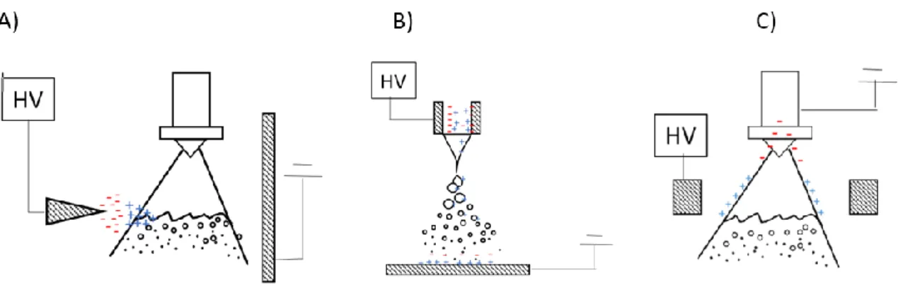
Figure 1-2- Schematic representation of charging mechanisms. A) corona charging; B) contact charging and C) induction charging ... 7
Figure 1-3 Electric circuit as schematization of induction charging system ... 9
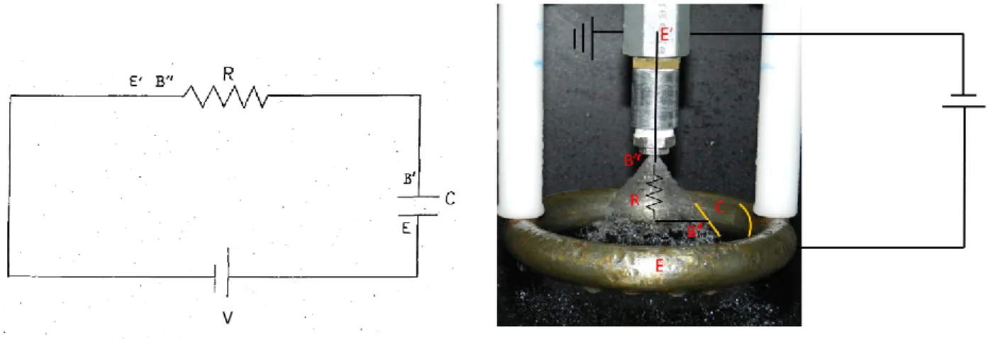
Figure 1-4- Electrical circuit with a toroidal electrode and a pressure hollow cone nozzle [I] ... 9
Figure 1-5- Inner Wetting (left) and outer wetting (right) of the nozzle [44] ... 11
Figure 1-6- Electrospray modes. A) enhanced dripping mode. B) microdripping. C) spindle mode [33] ... 12
Figure 1-7- Cone jet mode with varicose breakup (left) and whipping breakup (right) [47] ... 13
Figure 1-8 Simple jet mode with varicose breakup (A), whipping breakup (B) and ramified breakup (C). The picture C) was taken from [49] ... 14
Figure 1-9- Electrospray mode map as function of electric potential and liquid flow rate [25] ... 15
Figure 2-1 One dimensional representation of symmetric(a) and antisymmetric instabilities (b) ... 22
Figure 2-2- Varicose wave (left) and sinusoidal wave (right) [3] ... 22
Figure 2-3-Critical Weber number for sinuous long and short waves ... 25
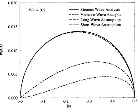
Figure 2-4- Sinuous and varicose waves for inviscid liquid sheet at Weber number = 0.5 ... 26
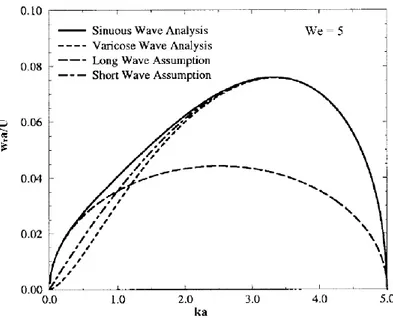
Figure 2-5-- Sinuous and varicose waves for inviscid liquid sheet s at Weber number = 5 ... 27
Figure 2-6--Sinuous long and short waves for viscous liquid sheet at We= 5 ... 28
Figure 2-7- Sinuous long and short waves for viscous liquid sheet at We= 0.5 ... 28
Figure 2-8- Wavy sheet scheme and coordinate system... 29
Figure 2-9-Lisa model of sheet primary atomization [61] ... 31
Figure 2-10- Different secondary atomization breakup modes at different Weber numbers [63] ... 33
Figure 2-11- Secondary atomization modes as function of Weber and Ohnesorge numbers [63] ... 33
Figure 2-12- Representation of induction charging system as an electrical circuit. Left: model, right: experimental setup... 38
Figure 2-13-Leonardo Da Vinci scheme of liquid jet breakup [70] ... 42
Figure 3-1- Experimental Rig. 1: water tank, 2: pump, 3: inverter, 4: flow meter, 5: pressure gauge, 6: HV power supply, 7: droplet charge unit (DCU), 8: Faraday pail, 9: water collector, 10: electrometer, 11: computer to elaborate experimental results. The red line indicates the high-tension connection, while the blue line is the liquid flow path. ... 53
Figure 3-2- Breakup length and spray angle. In the pictures the nozzle 216.364 at P=3 bar is reported at 0 kV (left) and at V=10 kV (right). The dotted line divides the primary and secondary atomization zones. ... 54
Figure 3-3- Breakup Length Lb (left), droplets current Idrop and D-CMR (right) as function of applied voltages at different pressures. ... 55
Figure 3-4- Comparison of breakup length ((left) and Droplet charge to mass ratio/droplets current (right) at different voltages for nozzles LC Nozzle ... 55
Figure 3-5- Breakup mechanism for tested nozzle ... 57
Figure 3-6 Electrical surface tension as function of applied electric potentials at different liquid pressure for the nozzle SS-BD5. ... 58
Figure 3-7- Comparison of experimental and theoretical Droplet Charge to Mass Ratio for SS-BD5. ... 61
Figure 3-8- Comparison of experimental and theoretical Droplet Charge to Mass Ratio for LC-nozzles. ... 61
Figure 4-1- Liquid jet breakup mechanism for the nozzle BD5 at P=3 bar [32]. ... 68
Figure 4-2- Breakup length as a function of the theoretical prediction for all tested nozzles. ... 70
Figure 4-3- Experimental breakup length (left graphs) and spray angle (right graphs) as a function of charging potential at different pressures for BD5, BD8 and BD10... 72
II Figure 4-5-. Wave profile on liquid surface for nozzle BD5 at P= 2 bar and rising charging potential V= 0 kV
(a), V= 4 kV (b), V= 8 kV (c), V= 12 kV (d), V=16 kV (e) and V=20 kV (f)... 75
Figure 5-1- Experimental set-up 1: Electrospray unit; 2: High Voltage (HV) power supply; 3: Syringe pump; 4: Back light; 5: High-Speed Camera; 6: Water tank. Solid line: water; dash dot-line: Electric circuit ... 83
Figure 5-2-1) Jet parameters as jet diameter and breakup length; 2) major and minor axes of a droplet .... 85
Figure 5-3- Sampling of droplets’ images for nozzle N2 at We=7.11 and different Bond numbers ... 86
Figure 5-4- Superimposition of 100 frames (A) and 500 frames (B) at We=7.11 and B= 5295.8 for N1 ... 87
Figure 5-5- Probability Density Functions for N2 at We= 7.11 and at six different Bond numbers ... 87
Figure 5-6- Cumulative Density Functions (CDFs) at different Bond numbers and at We= 7.11 for N1 ... 88
Figure 5-7- Electric current versus Bond number for nozzle N1, N2 and N3. ... 89
Figure 5-8- Diameter d50 versus Bond number for the three nozzles at different Weber numbers. Whipping line for We=3.16: Dash-dot line; Whipping line for We=4.93: dot line: Whipping line for We=7.11: dot-dash line... 89
Figure 5-9- Ratio between the electrical and surface tension stresses, R, for different Weber and Bond numbers for the three nozzles N1, N2 and N3. Whipping line for We=3.16: Dash-dot-dot line; Whipping line for We=4.93: dot line: Whipping line for We=7.11: dot-dash line. ... 90
Figure 5-10- Liquid jet whipping breakup (left) and corona fluorescence (right) for N2 and We3... 91
Figure 5-11- Number of droplets produced per second n, interface area of droplets Ai, circularity C, at different Bond and Weber numbers. Whipping line for We1: Dash-dot-dot line; Whipping line for We2: dot line: Whipping line for We3: dot-dash line. ... 92
Figure 6-1- Atomization process of an hydraulic water spray (left) and secondary atomization droplets (right) ... 98
Figure 6-2.Representation of liquid cone parameters as cone radius, r, breakup length, Lb, and half spray angle, θ/2. ... 100
Figure 6-3- PDFs at different electric potentials for nozzle BD8 at P=3 bar ... 101
Figure 6-4- Cumulative Density Functions at different electric potentials for nozzle BD8 at P=3bar and QL= 6.3 L/min. ... 102
Figure 6-5- Diameter d70 versus electric potential for nozzle BD8 at P=3bar ... 103
Figure 6-6 Droplets electric current, Idrop, and diameter d70 at different electric potentials for nozzle BD8 at P=3 bar. ... 103
Figure 6-7- Ratio R and Idrop versus the electric potential for the nozzle BD8 at P=3 bar. ... 105
III
List of Tables
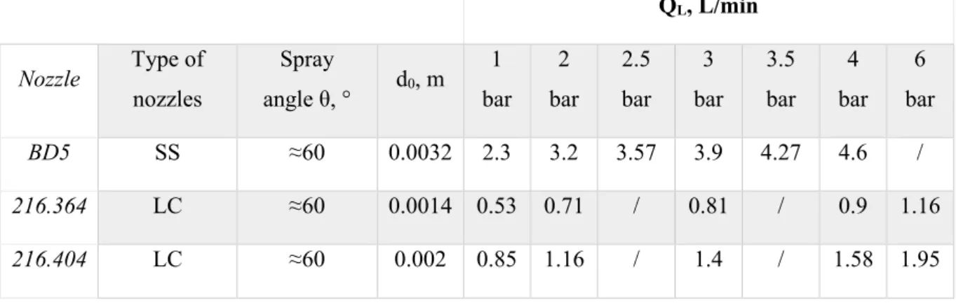
Table 3-1- Summary of fluid-dynamic properties of tested nozzle. SS: Spraying System; LC: Lechler ... 54 Table 4-1- Chemical speciation of tap water ... 67 Table 4-2-- Experimental results in uncharged conditions ... 69 Table 4-3-Values of the asymptotic values of the liquid jet breakup, Lv∞, the asymptotic potential, V∞, and of
the characteristic charging potential, Φ for all tested nozzles together with the corresponding values of the standard error and the coefficients of correlation ... 74 Table 5-1- Lower and higher values of Bond numbers for whipping transition observed from electrical and optical tests. ... 91 Table 6-1- 70th percentile at V=0kV and V=Vmin, percentage of reduction for all tested nozzles. *Discharge
IV
Nomenclature
Latin
a Major axe of droplet (mm)
ab Half sheet thickness at breakup (mm)
a0 initial sheet thickness (mm)
Aa air core area; Aa= π 4(do− 2a0) 2 (m2) Ao orifice area; Ao = π 4do 2 (m2)
Ap total inlet port area (m2)
Aj area of liquid jet (m2)
Ai Interface area of droplets (m2/s)
B’ inlet of grounded electrode (m) B jet breakup point (m)
Be Electrical Bond number (-)
Be,L Lower value of Bond number at whipping breakup inception from electrical results (-)
Be,H Upper value of Bond number at whipping breakup inception from electrical results (-)
Bi,L Lower value of Bond number at whipping breakup inception from imaging results (-)
Bi,H Upper value of Bond number at whipping breakup inception from imaging results (-)
CDF Cumulative Density Function (-) C condenser capacitor (C/V) Ci Droplet Circularity (-) Ct Constant (-)
CD discharge coefficient (-)
d50 50th percentile of droplets’ size distribution (m)
d70 70th percentile of droplets’ size distribution (m)
d90 90th percentile of droplets’ size distributions (m)
d10 10th percentile of droplets’ size distributions (m)
dL ligament diameter (mm)
dD droplet diameter (mm)
djet diameter of liquid jet (m)
dw Diameter of droplets with whipping breakup (m)
dv Diameter of droplets with varicose breakup (m)
D32 Sauter mean diameter (m)
Ds swirl chamber diameter, coincident with Dn (m)
d0 orifice diameter of nozzle (m)
Dpo entry port nozzle diameter (m)
Dn diameter of nozzle narrowest section (m)
D-CMR droplet charge to mass ratio (µC/kg) D electric displacement vector (C/m2)
E electric field (V/m)
fe volumetric electric force (N/m3)
f breakup parameter (-) Fp total air pressure force (N)
F pump frequency (Hz)
V Fs surface tension force (N)
Fµ viscosity force (N)
FG gravity force (N)
Fel electric force (N)
FE electric force/Coulomb force (N)
FIm image force (N)
Fint air-liquid interaction force (N)
h wave amplitude (-) h0 initial wave amplitude
H magnetic vector (A/m) Hm magnetic field (A/m)
Hj liquid jet height (m)
i current intensity (A) Idrop Droplets’ current (A)
Igen HV power supply current (A)
Inozzle Nozzle current (A)
I identity tensor (N/m) Jc current density (A/m2)
k wave number (m-1)
K Conductivity (K)
Kv velocity coefficient (-)
KL Constant (-)
KS wave number corresponding at ΩS (kmax) (m-1)
Lb breakup length (m)
Lb, ∞ Breakup length at asymptote (m)
Lb, th Theoretical breakup length (m)
L distance from the beginning of electric fiend to breakup point (m) Lo length of orifice (m)
m Rosin-Rammler coefficient (-) mL mass of a liquid ligament (Kg)
p perimeter of liquid jet (m) PDF Probability Density Function (-)
P80 Rosin-Rammler distribution coefficient (-)
P Pressure (atm)
q electric charge (C )
qv droplet specific charge (C/m3)
qD droplet charge (C )
qsat1 Parameter (-)
qsat2 Parameter (-)
QL liquid flow rate (L/min)
QR Rayleigh charge (C)
QE charge of electrode (C)
Q total electric charge (C) rc cone radius (m)
rp Euclidian distance between nozzle and electrode (m)
VI Rj liquid jet radius (m)
Rc circuit resistance (Ohm)
t Time (s)
Tm mechanical stress tensor (N/m)
Te electric stress tensor (N/m)
u axial component of liquid velocity (m/s) u̅ mean axial component of liquid velocity (m/s) u’ fluctuating axial component of liquid velocity (m/s)
u’I irrotational component of fluctuating axial liquid velocity (m/s)
u’R solenoidal component of fluctuating axial liquid velocity (m/s)
Ub liquid velocity at breakup point (m/s)
U liquid velocity (m/s)
U0 liquid-gas relative velocity, equal to U (m/s)
UG air velocity (m/s)
vs liquid sheet velocity (m/s)
v’I irrotational component of fluctuating radial liquid velocity (m/s)
v’R solenoidal component of fluctuating radial liquid velocity (m/s)
v̅ mean radial component of liquid velocity (m/s) v’ fluctuating radial component of liquid velocity (m/s)
vL radial component of relative velocity U (it is indicated as v) (m/s)
vjet Liquid jet velocity (m/s)
va0 initial air velocity (m/s)
vL0 initial liquid velocity (m/s)
vr air-liquid relative velocity (m/s)
V Electric potential (kV)
V∞ Electric potential at asymptote of breakup length (kV)
Vmin Electric potential at which the droplets current has its minimum value (kV)
Vopt electric potential corresponding at maximum value of D-CMR (kV)
Vd volume of a detached liquid ligament (m3)
Vw Whipping electric potential (kV)
ws liquid cone width (m)
x distance between electrode and liquid surface for a plate electrode (m) X ratio of air core area to air of final discharge orifice, X =Aa
Ao (-) Z distance between nozzle exit and centre of electrode (m)
We Weber number, We=
ρGUL2D0 𝛾 (-) Rei inlet Reynolds number, Rei=
ρLQLDpo μLAp (-) Re Reynolds number, Re= ρLUD0 μL (-) Oh Ohnesorge number, Oh = √ρμL Ldd𝛾 (-) Greek α Parameter (-) β phase angle (°) β’ Corrective factor (-) γ Surface tension (N/m)
VII γe Electrical surface tension (N/m)
εa relative air permittivity (-)
εL relative liquid permittivity (-)
ε0 dielectric permittivity of vacuum (F/m)
εr relative permittivity (F/m)
ξ Ratio between gas and liquid densities (-) ξLb Variation of breakup length (m/m)
η disturbance on liquid sheet (-) η0 initial disturbance on liquid sheet (-)
θ half spray angle (°)
λ Wavelength (-)
λ’ length of disintegrated volume (m) σ Surface charge density (C∙m-2)
σvol Volumetric density charge (C/m3)
µg gas viscosity (Pa∙s)
µm magnetic permittivity (H/m)
µL liquid viscosity (Pa∙s)
ρL liquid density (Kg/m3)
ρG gas density (Kg/m3)
ρs superficial charge density (C/m2)
ρe volume charge density (C/m3)
τb Breakup time (s)
τ relaxation time (s) ϰ1 Parameter (-)
ϰ2 Parameter (-)
ϕ Charging characteristic potential (kV) ϕL velocity potential function (-)
ϕV volumetric drop fraction (-)
Ψ(d) Volumetric diameter size distribution (-) Ψ(ds) Surface diameter size distribution (-)
ω, complex wave growth rate (m/s) ωr real wave growth rate (m/s)
ωi imaginary wave growth rate (m/s)
ΩS maximum value of real wave growth rate (ωmax) (m/s)
VIII
Abstract
The research is focused on water sprays electrified by induction charging through an external electric field. The aim of this work is to verify and understand how the breakup mechanism of a liquid jet and the droplets’ size population are influenced by the electric field.
Two experimental rigs were tested, and they will be named in the text as high-flow rate electrified spray (≈ L/min) and low-flow rate electrified spray (≈ mL/h). The choice to carry experiments on different scaled setup is due to the geometrical simplicity that the low-flow rate water spray system displays, which helped to better understand the physics beyond the electrification of a liquid jet.
In both systems, the liquid was water pumped in a grounded nozzle. The liquid jet crossed an electric field generated by a toroidal ring connected to the HV power supply and placed around the jet itself. The experiments were conducted to estimate: i) the electric current (or the specific charge) acquired by the droplets, ii) the droplets’ size population at different electric potentials.
For what concerns the high-flow rate electrified spray, hollow cone hydraulic nozzles were used. We found that the droplets current had a non-monotonic trend with the applied electric voltage: it increased linearly until to reach the optimum value and, after that point, it started to decrease fast. At same time, the breakup mechanism was influenced by the electric field. Indeed, for the primary breakup parameters, we observed that the breakup length reduced with the potential of about 20 %compared with the uncharged value until to reach an asymptotic value, while the spray angle enlarged due to the repulsion between equally charged droplets. In the secondary atomization, the droplets’ size distribution shifted toward smaller diameters as the electric potential increased. The percentile diameter, d70, chosen to represent the distribution, was quite constant for
all the potentials from 0 kV until the potential at which the electric current was maximum. As soon as the current overcome the optimum point, the d70 started to reduce swiftly. In these conditions, the dimensionless
ratio between the electrical stress and the surface tension stress, R, rise and become larger than 1, as confirmation of the effective influence of the electric field on liquid jet dynamics. We envisage that the insurgence of corona discharge on liquid jet surface could explain these phenomena.
This hypothesis was confirmed by the experiments made on the low-flow rate electrified sprays or electrospray. In fact, this experimental rig was used to carry studied on the simple jet mode with whipping breakup, where the whipping is an off-axe instability that generates droplets much smaller that the nozzle inner diameter. The tests revealed that as soon as the electric current increased with the potential and the whipping instability took place on the liquid jet surface, the droplets’ size population were composed by droplets of size smaller than 0.5 mm. When it happens, the electrical stress overcomes the surface tension, as observed for the high-flow rate spray, and the corona discharge glow took place. It was confirmed by ad-hoc experiments made in a black-room.
The results confirmed that the presence of the electric field modifies significantly the liquid jet atomization dynamic. It could be used to manipulate the droplets’ distribution accordingly to the require application.
1
Chapter 1. Introduction
pic by L. Manna
1.1 Aim of the work
Electrified sprays are adopted in a large number of industrial and medical applications and are present in several natural processes, as, for example, in waterfalls [1]. Water electrification is not so common, but the large use water in chemical engineering processes trigger our attention on this special application. It was proved, for example, the electrified water can be proficiently used to improve the efficiency of gas absorption and submicron particle capture [2], [3] and that electrification can be used to promote water treatments or desalinization processes [4].
All of these processes require treatment of high-water flow rates, which can be achieved either by using conventional spray nozzles, with typical flow rates of several L/min, or arrays of small nozzles. In the first case, the atomization technology is already available at commercial level, but the electrification process was scarcely analysed. In the second case, the electrification of a single nozzle is well known, but the use of multiple sprays has several limitations and is still the subject of explorative studies so far.
The main aim of this research is to better understand the fundamental processes involved in the generation of electrically charged sprays from large flow rate conventional hydraulic nozzles as well as to investigate the mechanisms involved in the transition of varicose and whipping atomization mode in low flow rate EHDA. In this study, we explored the electrified water sprays for conventional hydraulic nozzles (flow rates between 3 and 10 L/min) and single nozzles operated at high flow rates (up to 1000 mL/h). The main objectives of this work were 1) to evaluate how the presence of an electric field influences the atomization mechanism and 2) to investigate how the morphology and parameters of sprayed droplets change with electric voltage.
For hydraulic sprays, at the best of our knowledge, some authors carried experiments on electrified water sprays observing a reduction of the breakup length and an enlargement of the spray angle with the electric field [5], while another paper indicated a reduction of about 4% of droplets’ diameter [6]. However, the most of studies conducted on high flow rate electrified water sprays assumed that the atomization mechanism is not influenced by the electric field [7].
2 On the contrary, the electrified sprays at low-flow rate have been widely described over the years and semi-empirical correlations that connect electrification and atomization have been developed. However, some phenomena as the whipping breakup establishment are still partially unknow.
The research investigated the primary and secondary atomization mechanisms as a function of electrification, coupling dedicated electrical measures to determine the spray electric charge and optical analyses to investigate the morphology of the liquid lamina and of the sprayed droplets.
Tests with hydraulic sprays were carried out with different kinds of swirl hollow cone nozzles. Tests with nozzles were focused on high flow rates applications, which can be obtained by operating in the so-called whipping mode. This mode is scarcely studied in the literature and, but we envisage that, for its many analogies with the large sprays, its study may provide valuable information to improve our understanding of the underpinning physics of water electrification of hydraulic sprays.
The thesis is organized in six chapters. In this chapter, the basic physics of both spray technology and induction charging mechanism is described, while the models at which the study referred to and a critical literature review are discussed in Chapter 2.
The experimental results are showed and described in Chapter 3-6, which are based on publications or paper on submission, listed at the end of the work. In particular, Chapter 3 is focused on the induction charging and on the primary atomization of electrified water spray at high flow rates of nozzles produced by different companies. Chapter 4 and 6 are based on exploring the effect of electric field on both primary and secondary atomization of hydraulic nozzles made by a single manufacturer, respectively, while chapter 5 shows the results of experimental campaign carried on low-flow rate electrified spray. The choice to interpose Chapter 5 in between the results on atomization process of high-flow rate electrified sprays (e.g. Chapters 4 and 6) is due to the fact that the observations made in Chapter 6 on secondary atomization of hydraulic nozzles are consequence of experimental evidences found and showed in Chapter 5.
Each Chapter from 3 to 6 is organized in i) an introduction section to the specific issue faced in the chapter itself, ii) the description of experimental campaign, iii) discussion of experimental results, iv) summary of the chapter. At last, the conclusion of the research is discussed.
1.2 General physics
A spray is a two phases system of liquid droplets in a gaseous stream and the droplets can be accelerated, decelerated, deformed or broken by interactions with the gaseous phase. The spray is characterized by a wide spectrum of droplets’ size that represent the quality of an atomization process. The process of atomization is the disintegration of a liquid jet or a cone in a wide spectrum of droplets. It can be induced by the kinetic energy of the liquid itself, or by a fast air stream or by a mechanical energy applied externally through a rotating or vibrating device. It is a keystone of many chemical and mechanical engineering applications that involve a two phase system of liquids as dispersed phase in a gaseous stream: surface coating, fuel injections, water
3 scrubbing, drug delivery in medical therapy, synthesis of nanoparticles are some of the possible field of application [7], [8].
Generally, the liquids atomization process has been widely studied over the years and the droplets’ distribution, ψ(dD), depends on the way the liquid cone generates, and it means that it is related to the liquid flow rate and
surrounding air pressure and to nozzle geometrical parameters. Indeed, the spraying performances turn upon orifice diameter d0, length of orifice Lo and half spray angle θ/2, specially for pressure-swirl atomizers, which
have been tested in this work [8]–[11].
The efficiency of a spray generated by a pressure swirl hollow cone nozzle is evaluated by the discharge coefficient CD. It defines the actual flow rate when a fluid crosses a nozzle or a generic constriction. In fact, it
is the ratio between the actual flow rate to the theoretical one. Several relations have been written for the discharge coefficient and they differ for the nozzle. For a swirl nozzle, it is calculated as:
𝐶𝐷= [ (1−𝑋)3
1+𝑋 ] 0.5
(1.1) where X is the ratio of air core area Aa and the orifice area A0, which are strictly dependent on type of used
nozzle.
Generally, it is low because of the presence of air core. It was noted a dependence of discharge coefficient from Reynolds number [12]. For low Reynolds number, the liquid viscosity thickens the sheet and the discharge coefficient increases; for large Reynolds number (from 3000 on), the CD is independent of Reynolds
number. It was evaluated a gap between the theoretical discharge coefficient and the experimental one [13]. To reduce this difference, a correcting factor was added at the Equation (1.1):
𝐶𝐷= 1.17 [(1−𝑋) 3 1+𝑋 ]
0.5
(1.2)
For pressure swirl nozzles, the discharge coefficient can be expressed as dependent on both nozzle geometry and pressure gauge:
𝐶𝐷= 𝑄𝐿 𝐴0(∆𝑃 𝜌⁄ 𝐿)
0.5 (1.3)
where QL is the liquid flow rate, ΔP is the difference between the injection pressure and the ambient pressure
and ρL is the liquid density.
The air core, Aa, develops only above a critical Reynolds inlet number, defined as
𝑅𝑒𝑖 =
𝜌𝐿𝑄𝐿𝑑𝑝𝑜
𝜇𝐿𝐴𝑝 (1.4)
where Ap is the total port inlet area, entry port diameter dpo and μL is liquid viscosity.
In fact, for Reynolds numbers lower than the critical one, a full jet exits from the nozzle and a solid cone spray is formed. The air core diameter and its turbulence characteristics influence the droplets size distribution in terms of mean diameter and number of droplets. The larger the air core diameter, the thinner the liquid sheet
4 thickness, the finer drops. For a given pressure drop, the air core reduces the effective flow area causing a reduction in discharge coefficient. For large Rei values, the discharge coefficient is not dependent on it [12].
Giffen and Muraszew [13] developed a correlation between the nozzle geometry (ds diameter of a swirl
chamber when it is present) and the air core: ( 𝐴𝑃 𝑑𝑆∙𝑑0) 2 =𝜋2 32∙ (1−𝑋)3 𝑋2 (1.5)
where ds is the diameter of swirl chamber in pressure swirl nozzles.
Once the nozzle geometry was known, the relation (1.5) was used to evaluate the value of ratio X. The thickness of the liquid sheet, a0, was calculated from equation (1.6):
𝑋 =(𝑑0−2𝑎0)2
𝑑02 (1.6)
As relation (1.6) indicates, the area of air core influences strictly the liquid sheet thickness a0. Rizk and
Lefebvre [14] studied the influence of nozzle geometry (d0), liquid physical properties and operative conditions
(P and QL) on liquid sheet thickness a0:
𝑎02=
1560∙𝑄𝐿∙𝜇𝐿 𝑑0∙∆𝑃𝐿 ∙
1+𝑋
(1−𝑋)2 (1.7)
Higher pressure provides thinner liquid sheets. Indeed, the atomization quality, in terms of droplets’ size distributions’ spread, improves by increasing the nozzle pressure or rather the liquid discharge velocity and so the liquid film thickness reduces. A thicker film is obtained by a larger orifice diameter due to lower discharge coefficients. At last, the smaller the nozzle diameter, the larger the film thickness, because the air core diameter is smaller, and the nozzle swirl action is reduced. Regarding the fluid physical properties, liquid viscosity influences the sheet thickness. Viscous forces resist the disruption and consequently the film thickness increases. The relation (1.7) was confirmed by experimental results [14]. When 𝑎0
𝑑0 ⁄ ≪ 1, the relation (1.7) can be simplified in 𝑎0= 3.66 ( 𝑑𝑜𝑄𝐿𝜇𝐿 𝜌𝐿∆𝑃 ) 0.25 (1.8)
The Equation (1.8) shows that the thickness a0 has not a linear dependence on these parameters, but it depends
on them through a coefficient 0.25.
The corresponding of discharge coefficient in terms of liquid velocity is the velocity coefficient Kv. It is defined
as the ratio of actual discharge velocity to the theoretical one: 𝐾𝑣=
𝑈 (2∆𝑃 𝜌⁄ 𝐿)0.5
(1.9)
where U is the liquid velocity.
5 𝐾𝑣=
𝐶𝐷
(1−𝑋) cos 𝜃 (1.10)
A reduction of both discharge velocity and of velocity coefficient is achieved by a large orifice diameter and consequently a thinner sheet. On the contrary, an improvement of velocity coefficient at higher pressure levels leads to a reduction in liquid film thickness.
Schmidt et al. [15] proposed different relations to evaluate the velocity coefficient. They assumed that the exit velocity profile was uniform, and the velocity U was given by Equation 1.9. The velocity coefficient ranged between two values:
𝐾𝑣= 𝑚𝑎𝑥 [0.7, 4𝑄𝐿 𝜋𝑑02∙cos 𝜃√
𝜌𝐿
2∆𝑃] (1.11)
The spray angle is influenced by nozzle geometry. According to Taylor’s theory [16], it is a function of ratio of inlet port area and the product between the nozzle chamber diameter and orifice diameter. Figure 1-1 reports the theoretical prediction of spray angle in comparison to the experimental one. It was obtained for a non-viscous liquid, and indeed, the experimental data show a difference of 3° for cone angle of 60° due to liquid viscosity.
Figure 1-1 Relationship between cone angle and nozzle geometry [16]
Giffen e Muraszew [13] found a relation for a non-viscous liquid between the spray angle and the nozzle geometry:
sin 𝜃 = 𝜋⁄ ∙𝐶2 𝐷
𝑐𝑜𝑛𝑠𝑡∙(1+√𝑋) (1.12)
The relation (1.12) correlated the spray angle with the air core (X), and both the type of liquid and operative conditions (CD).
The spray parameters here described for a hollow cone could be modified and improved by applying external forces to the spray, as an electrical force. When an electric field is applied, the electric charge acquired by liquid droplets is spread on external surface: the spray delivers inside positive and negative charge, but it is globally electrically neutral. The combination of aerodynamic and electrostatic forces improves the dispersion
6 of liquids in gas, generates smaller droplets and supports the exploitation of electrified sprays in many research fields as drug delivery, agricultural spray, industrial and food processes or air pollution control [17].
The charging efficiency is strictly related to droplets size: the smaller the droplets size, the higher the charge. Anyway, if the droplets are too small, they become fluid-dynamically uncontrollable and, in a hot system, they evaporate causing a loss of droplet charge.
A liquid droplet in an electric field exerts an electric force, which is opposite to cohesive forces in the liquid as the surface tension force. When the electric force overcomes the surface force, the droplet goes off. The ratio between the two main forces acting on a liquid jet is expressed as [18]–[20]:
𝑅 = 𝜎2 4𝜀0 ⁄ 𝛾 𝐿 ⁄ (1.13)
Where σ is the surface density charge, γ is the surface tension, ε0 is the vacuum permittivity and L is the
characteristic length on which the stresses are applied, and it can be the liquid jet diameter or the mean droplet diameter. This relation has been developed for low-flow rate liquid jets (≈μL/min) and for dielectric liquids but it could be generalized by specified the liquid physical properties and the characteristic length, L.
Once an electrical field is applied, a droplet cannot acquire a number of charges indefinitely, but it exists a limit charge level called Rayleigh limit, QR. For a droplet of a diameter dD, it is expressed as:
𝑄𝑅= √8𝜋2𝛾𝜀0𝑑𝐷3 (1.14)
Actually, the liquid charge on sprays is complicated to measure and this is the reason why the charging level on droplets is expressed as ratio of spray current, Idrop, and liquid flow rate, QL. This ratio is the droplets specific
charge or Droplet Charge to Mass ratio (D-CMR): 𝐷 − 𝐶𝑀𝑅 = 𝐼𝑑𝑟𝑜𝑝
𝑄𝐿 (1.15)
The D-CMR is dependent on electric field strength (applied potential), liquid flow rate, liquid physical properties and droplets diameter. The D-CMR can be increased by changing one of former parameters. Ha et al. [21] employed sea water as liquid spraying in induction charging atomization to capture particles emitted by marine engines. The measured droplets specific charge was higher than the same calculated with tap water. The result was explained by the greater seawater conductivity due to salts presence (3.21 S/m instead of 0.75 S/m): in water, the salts released ions, and these enhanced the charging phenomenon. Indeed, the liquid conductivity, which represents the property of a liquid to transport charges when an electric field or a potential difference is applied, increases in presence of aqueous impurities. Some experimental tests that we are carrying by changing the liquid conductivity confirm that the droplets current increases proportionally to liquid conductivity. The same trend is observed if the electric field is more intense or if the liquid flow rate is increased due to the larger number of droplets that carry an electric charge
7
1.3 Charging Mechanism
There are three main technological approaches to spray charging, as shown in Figure 1-2: exposure to corona ions (A), contact charging (B) and induction charging (C).
Figure 1-2- Schematic representation of charging mechanisms. A) corona charging; B) contact charging and C) induction charging
In corona charging (A), the liquid droplets are charged by bombardment of fast moving ions, generated from a nozzle connected to high potentials, on the surface of the droplets and it is also denoted as ion attachment. Via corona charging, the charge acquired by the droplets has the same polarity of the applied voltage. The level of charge is dependent on the dielectric constant of the medium, its surface area, the electrical characteristics of the corona discharge and the residence time within the ionized field. In corona charging, the Rayleigh percentage is about 5% and it is usually used at very low liquid flow rate (≈ mL/min). In contact charging (B), the liquid is emitted from a nozzle and it is exposed to a strong electric field. In this type of mechanism, the liquid flow rate is relatively low (≈ μL/min), charging of liquid droplets is strictly correlated to atomization process or electrospray modes [22]. Therefore, the electric charge is directly transferred to the liquid surface and it is trapped into droplets while these are forming. In the induction charging (C), a positively or negatively charged HV electrode is held near a grounded spray nozzle. The liquid cone is polarized: the liquid exiting from the nozzle breaks up due to natural surface instability phenomena and the formed droplets trap a charge opposite to electrode one, while the free charges with same polarity of electrode move towards the ground via the nozzle [23]. Highest charging level is reached by means contact charging: the ratio between the droplet charge, QD, and the Rayleigh charge limit, QR, is about 30- 40%. If the liquid flow rate is about
L/min, the induction charging is the reasonable mechanism, but the Rayleigh percentage is low and about the 10%.
Generally, the contact charge mechanism used for low-flow rate sprays and it is denoted as electrospray [24]. Actually, the electrospray refers to any electrified spray at liquid flow rates about few μL/h or mL/h in nozzles with inner diameters of hundreds of micrometers. It means that an electrospray can be performed even with a nozzle grounded and a counter-electrode connected to a HV power supply [25].
8 In this work, two different experimental rigs of electrified sprays were tested, and both were charged by induction charging. In the first one, pressure swirl atomizers were used, and the liquid flow rate was about L/min, while in the second one smooth nozzle were tested at liquid flow rate of few mL/h. The two experimental rigs will be referred in this work as high-flowrate and low-flowrate spray from here on.
1.3.1 High flow rate electrified spray
As discussed, the induction charging is the best compromise between water flow rate and charging level. When the induction charging is applied on a high flow rate water spray, the induction charging is effective if the fluid is sufficiently conductive to allow an efficient charge transfer to droplets during spray formation [23], [26]. It means that the charge relaxation time, τ, has to be much smaller that droplets formation time, τb. The former
time indicates how fast the charges are transferred to a liquid, while the latter one describes how fast the liquid disrupts in droplets.
If the liquid is tap water with electrical conductivity K of 0.0715 S/m, the relaxation time can be evaluated: 𝜏 = 𝜀0∙𝜀𝑟
𝐾 =
8.85∙10−12∙78.5
0.0715 = 9.71 ∙ 10
−8𝑠 (1.16)
where εr is the relative permittivity. The droplets formation time is expressed as:
𝜏𝑏 = 𝐿𝑏
𝑈 (1.17)
where Lb is the breakup length and U is the liquid jet velocity. It means that the induction charging depends
on liquid physical properties. It is indicated that the minimum liquid conductivity required for induction charging is 10-10 S/m [27]. Thanks to its high conductivity, water is an appropriate candidate to electrified
spray, but electrification of water sprays is more unstable than that of dielectric and/or organic liquids [28] because of ionic composition and because its physical properties are subject to substantial change in presence of electric field [29].
Considering that the liquid cone surface and the electrode are held at different electric potentials, the system can be schematized as a condenser. The driving force is the Coulombian interaction between negative and positive charges:
𝐹𝐸 = 𝑄𝐷𝑄𝐸
4𝜋𝜀0𝑟𝑝2 (1.18) where rp is the Euclidian distance between the electrode and the nozzle, QE is the electrode charge. It is a
function of the potential V and the condenser capacitor C:
𝑄𝐸= 𝐶𝑉 (1.19) The system electrode-sprayed liquid surface as a condenser is represented in Figure 1-3:
9
Figure 1-3 Electric circuit as schematization of induction charging system
Where V is the potential difference, T is the switch, C represents the condenser and R is the whole system resistance. The negative side of condenser represents the electrode, and the positive one is the liquid surface. Once the switch is on, the electric current starts flowing from the electrode to the spray. The condenser capacitor changes with electrode geometry. The electrode can be formed by two parallel and flat plates, or by a toroidal ring. For a toroidal ring, the electric circuit is schematized as in Figure 1.4 where the electrode has a negative polarity and the liquid cone is positively charged.
Figure 1-4- Electrical circuit with a toroidal electrode and a pressure hollow cone nozzle [I]
For this system, the condenser capacity is defined as: 𝐶 =2𝜋𝜀0𝜀𝑟𝐿𝑏
ln(𝑥 𝑟𝑐)
(1.20)
where rc is the cone radius and it can be easily estimated once the breakup length, Lb, and the spray angle, θ,
are known. It is assumed to be constant, but it should be expressed as a function of liquid jet height r=r(Hj). The electrode surface charge density is given by:
𝜎 = 𝑄𝐸
4𝜋(𝑥−𝑟𝑐)2 (1.21) The spray current is:
𝑖 = 2𝜋𝑟𝑐𝑈𝜎 (1.22) The atomization mechanism of this type of spray is described in paragraph 2.1, even though atomization models that gather the electrification of the liquid cone are missing.
10 1.3.2 Low flow rate electrified spray
The electrification of sprays at low flow rate is denoted as ElectroHydroDynamic Atomization (EHDA) or electro-spraying. It is the deformation of liquid meniscus by the presence of electric field that overcomes the surface tension and disrupts the liquid in droplets [30]. If it is charged by contact, the liquid flows from a nozzle connected to a high voltage supply and it is collected on a grounded counter-electrode. Otherwise, the nozzle is grounded, and the counter-electrode is connected to high voltage power supply (induction charging). The EHD atomization can be performed with liquids whose surface tension and conductivity are at least higher than 50 mN/m and 10-11 S/m, respectively [24]. The surface tension and conductivity with the dielectric
permittivity are the liquid properties that mostly influence the atomization process because they denote the tendency of liquid to be influenced from the electric field. The electro-sprayed droplets acquire a level charge about 50-70% of Rayleigh limit [24].
The interest in this atomization and charging mechanism has swiftly rose in recent years, encouraged mainly by its new applications [31], [32]. The scientific and industrial applications of electrospraying can be roughly categorized into small-output and large-output processes [33]. The first category comprises ink-jet printing, micro- or nanopatterning in electronics (non-contact alternative to photolithography), fuel injection, microparticle manufacturing for drug delivery [34], [35], thin film deposition[36], micromachining, nanoparticle sprays (e.g. in electrospray ionization for mass spectrometry of highly charged biological macromolecules [37]–[39]), ingredients dosage in the cosmetic and food industries. The second category gathers fire extinguishing, wet scrubbers (precipitation of dust or smoke)[40], [41], agriculture sprays crop protection (pesticides), spray coating [42] and painting, or ceramic films fabrication[43]. Moreover, the development of new detecting technologies (as high-speed camera or lasers) improved significantly the study of EHD atomization and the description of the phenomenology.
The behaviour and properties of the EHD spray depend on many different parameters, i.e. the liquid properties, nozzle geometry, wetting properties etc. Regarding the nozzle geometry, different nozzles designs can be employed, but the conventional cylindrical nozzle is the most common nozzle design [44] with inner diameters ranging from few micrometres to 1 mm [44]. The tip of the nozzle could be smooth or sharped but the second one is the less used to avoid electric discharges because of a too intense electric field nearby.
Two different wetting modes has been observed. They depend mainly on both type of nozzle geometry and material and on liquid physical properties [44]. In the first wetting mode, called inner wetting mode, the liquid generates a meniscus at the base of the nozzle equal to the inner diameter of the capillary. The second type is denoted outer wetting, and, in this case, the liquid meniscus covers the outer edge of the capillary. The two wetting types are shown in Figure 1-5.
11
Figure 1-5- Inner Wetting (left) and outer wetting (right) of the nozzle [44]
The setup used for electrospray is normally composed of a nozzle where a liquid is pumped through and a metallic counter-electrode (ring or plate) placed at a certain distance from it. Between them, a potential difference is applied to generate a strong electric field. In case of a ring-nozzle electrospray unit, two types of configurations are available: nozzle-ring up or nozzle-ring down. The difference between them is the direction and the strength of the electric field exerted on the liquid jet and consequently the atomization mechanisms. For a defined set-up geometry, liquid type and operating conditions (flow rate and electric potential), different “spraying modes” can be created [31]. Those modes are based on the shape of liquid meniscus at nozzle outlet and on type of liquid behaviour in its disintegration into droplets [30], [31]. They are generally classified on Weber number, which is the the ratio between the aerodynamic force and the surface tension force:
𝑊𝑒= 𝜌𝐺𝑑𝐷𝑈2
𝛾 (1.23) The modes are divided into “low- flow rate” modes (at Weber number lower than 1) in which the liquid is atomized directly at nozzle exit producing droplets (enhanced dripping mode, cone-jet mode) and into “high-flow rate” modes (We>4) that gathers the regimes in which the liquid elongates from the nozzle forming a continuous jet that breaks intro droplets (simple-jet mode) [19], [45], [46]. In between, the spray is in transition
regime, which has not been deeply investigated.
In the enhanced dripping mode, as showed in Figure 1-6-A, a train of droplets with equal size and reproducibility is produced. In this mode, the droplet size distribution is monodispersed, the droplet diameter is bigger than nozzle outer diameter.
Compared with the uncharged spray or dripping regime, the frequency of droplet emission in the enhanced dripping mode is increased. It is still valid the Rayleigh relation that the droplet diameter is about six times the nozzle inner diameter [47].
12
Figure 1-6- Electrospray modes. A) enhanced dripping mode. B) microdripping. C) spindle mode [33]
For distilled water, the droplet diameter decreases from 1000 µm (uncharged spray) to 300 µm (charged spray) with potential increase for a nozzle with inner diameter of 0.65 mm [30] . For liquids with conductivity lower than 10-6 S/m [22], as the electric potential increases, the droplets become smaller than those emitted in
dripping mode and their diameters are much smaller than nozzle inner diameter [31]: this mode is the micro-dripping mode (Figure 1-6-B). The micro-micro-dripping and the micro-dripping mode establish in a narrow window of
flow rates and voltages. As the flow rate and/or the potential are increased a bit, the liquid emerges as spindles in the direction of electric field and the mode turns into the spindle mode (Figure 1-6-C). The spindles disrupt in main and sibling droplets whose diameters range from 300 µm to 500 µm for the former and from 100 µm to 80 µm for the latter. For distilled water, this mode is observed at voltage about 9-11 kV [31]. As the electric potential increases, the number of points of spindles emission on nozzle surface becomes higher. In
multi-spindle mode, the droplets are produced in the same way of multi-spindle mode, but the multi-multi-spindles are not
observed simultaneously but they are emitted periodically from the nozzle surface and in opposite directions because of electrical repulsion [31].
At same potentials of spindle-mode but at higher flow rates, the cone-jet mode is observed. Generally, the electrostatic force opposes the surface tension force acting on liquid meniscus that is deformed generating the several spraying modes. When the electric stress and surface tension stress acting on the liquid surface are
13 balanced to form a conical-like surface, called Taylor cone, with a semi- vertical angle of 49.3° sprays out from the nozzle tip, as represented in Figure 1-7 [48]–[50].
From the cone tip, a filament elongates that breaks into the droplet distribution. Once the cone-jet mode is established, it is stable and let producing a continuous droplet flow. Different authors noted that the operating window in which it can be found is quite narrow [31], [34], [46], [51]. As observed by Cloupeau and Prunet-Foch [22], for liquids with low conductivity it is quite impossible to produce spontaneously fine jets in the
cone-jet mode.
The cone-jet mode appears when a minimum liquid flow rate is pumped through the nozzle. It is a function of liquid physical properties as dielectric permittivity, surface tension, density and conductivity [51]. The advantage of this mechanism is related to droplets size that are smaller than 1 mm in some case even though the liquid flow rate is order of µL/min. This is the reason why it has been the most electrospray mode studied and used in industrial applications. Indeed, the droplet size and the current emitted in this mode could be predicted by scaling laws developed by studies conducted on dielectric liquids as ethanol, ethylene glycol and ethyl alcohol [30], [46], [51].
The droplet diameter, dD, is related to the liquid flow rate QL and physical properties as surface tension γ and
conductivity K in a generic form as [24], [44], [52]:
𝑑𝐷= 𝑐𝑜𝑛𝑠𝑡 ∙ (𝑄𝐿)𝑎∙ (𝛾 ∙ 𝐾)−𝑏 (1.24)
Hartman et al. [53] investigated the cone-jet mode breakup mechanism for different liquids. It was observed that the liquid jet elongated by the tip of the Taylor cone could assume two different breakup mechanisms: the varicose breakup and the whipping breakup. The dependence of droplet diameter on liquid flow rate depended on breakup mechanism and two correlations were found for the varicose breakup, dv, and whipping breakup,
dw, which are respectively:
𝑑𝑣≈ ( 𝜌𝜀0𝑄𝐿3 𝛾𝐾 ) 1/6 (1.25) 𝑑𝑤≈ ( 𝜀0𝑄𝐿 𝛾𝐾 ) 1/3 (1.26)
14 When the liquid inertia (e.g. the flow rate) is high enough to produce a stable jet and the electric potential is the same of the cone-jet mode, the mode is called simple-jet mode. The main difference between the cone-jet
mode and the simple-jet mode is the production of droplets. In the former, the jet emerges from the cone formed
at nozzle exit, in the latter the jet is emitted directly from the nozzle [45]. Agostinho et al. [45] observed that the simple-jet mode has three main breakup mechanisms: varicose breakup, whipping breakup and ramified breakup, showed in Figure 1-8.
Figure 1-8 Simple jet mode with varicose breakup (A), whipping breakup (B) and ramified breakup (C). The picture C) was taken from [49]
The former is comparable with the breakup mechanism of an uncharged jet in the jetting regime, but the presence of the electrical stresses can reduce the liquid jet radius, thus the droplet size as well [45]. The whipping breakup takes place when the electric stresses are high enough to create off-axis instabilities of the jet. The droplets size produced in the simple-jet mode is lower than nozzle diameter, but the high liquid flow rates make this electrospray mode suitable for application that need high flow rates, as observed by Agostinho et al. [45].
The liquid jet established at We>4 for an uncharged spray has a diameter dj almost equal to the nozzle inner
diameter or outer diameter if the nozzle wetting is inner or outer, respectively. The diameter of droplets detached from the liquid jet is 1.8 time the jet diameter [25], [45], [54], [55]. When the electric field is applied, the liquid jet diameter keeps preserving the same correlation with nozzle dimension, but the droplet diameter is deeply influenced by the electrification process. Indeed, in the simple jet mode with whipping breakup multi-modal distributions of droplets’ size were observed, as reported in Chapter 5.
Agostinho [25] resumed in a regime map how the liquid flow rate and the electric potential could influence the electrospray mode. The map is showed in Figure 1-9 and it is divided in three zone. The dripping regime zone at Weber lower than 4, the jetting regime at Weber larger than 4 and the transition regime zone in between. The dripping and jetting regimes include the electrospray modes that take place at low-flow rate and high flow rate, already described.
15
Figure 1-9- Electrospray mode map as function of electric potential and liquid flow rate [25]
The same author [19] suggested to correlate the electric potential with the nozzle geometry by a dimensionless number, the electric Bond number, express as:
𝐵𝑒 = 𝜀∙𝑉2
𝛾∙𝑑𝑖 (1.27)
Where di is the nozzle inner diameter. It is a comparison between the electric force and the surface tension and, most of all, it allows to compare experimental results made with the same liquid but different nozzles. .
16
1.4 References
[1] E. T. Pierce and A. L. Whitson, “Atmospheric Electricity and the Waterfalls of Yosemite Valley,” J.
Atmos. Sci., vol. 22, pp. 314–319, 1964.
[2] L. D’Addio, C. Carotenuto, W. Balachandran, A. Lancia, and F. Di Natale, “Experimental analysis on the capture of submicron particles (PM0.5) by wet electrostatic scrubbing,” Chem. Eng. Sci., vol. 106, pp. 222–230, 2014.
[3] C. Carotenuto, F. Di Natale, and A. Lancia, “Wet electrostatic scrubbers for the abatement of submicronic particulate,” Chem. Eng. J., vol. 165, no. 1, pp. 35–45, Nov. 2010.
[4] F. Di Natale, C. Carotenuto, L. Manna, and A. Lancia, “Chemi-electro-hydrodynamic of sulphur dioxide absorption by electrified water drops,” Chem. Eng. Trans., vol. 69, 2018.
[5] G. N. Laryea and S. Y. No, “Spray angle and breakup length of charge-injected electrostatic pressure-swirl nozzle,” J. Electrostat., vol. 60, no. 1, pp. 37–47, 2004.
[6] J. A. Marchant and R. Green, “An electrostatic charging system for hydraulic spray nozzles,” J.
Agric. Eng. Res., vol. 27, no. 4, pp. 309–319, 1982.
[7] A. Jaworek and A. Krupa, “Charged Sprays Generation,” in Sprays: Types, Technology and
Modeling, Maria C. Vella, Ed. Nova Science Publishers, Inc., 2011, pp. 1–100.
[8] C. Dumouchel, “On the experimental investigation on primary atomization of liquid streams,” Exp.
Fluids, vol. 45, no. 3, pp. 371–422, 2008.
[9] N. Ashgriz, Handbook of atomization and sprays: theory and applications, vol. 1. 2011.
[10] C. J. Clark and N. Dombrowski, “Aerodynamic Instability and Disintegration of Inviscid Liquid Sheets,” Proc. Roy. Soc. Lond. A, vol. 329, p. 467, 1972.
[11] P. K. Senecal, D. P. Schmidt, I. Nouar, C. J. Rutland, R. D. Reitz, and M. L. Corradini, “Modeling high-speed viscous liquid sheet atomization,” Int. J. Multiph. Flow, vol. 25, no. 6–7, pp. 1073–1097, 1999.
[12] A. Radcliffe, “The performance of a type of swirl atomizer,” in Proceedings of the Institution of
Mechanical Engineers, 1955.
[13] Edmund Giffen and A. Muraszew, Atomization of Liquid Fuels. Chapman & Hall, 1953. [14] Levebvre, Atomization and Sprays. .
[15] D. P. Schmidt et al., “Pressure-Swirl Atomization in the Near Field,” SAE Tech. Pap., vol. 1999, no. 1999-1–496, 1999.
17 [16] G. I. Taylor, “No The mechanics of Swirl Atomizers,” in Seventh International Congress of Applied
Mechanics, 1948, pp. 280–285.
[17] K. Tang, “The Electrospray: Fundamentals and Feasibility of its Application to Targeted Drug Delivery by Inhalation.” 1994.
[18] D. Camelot, J. C. M. Marijnissen, and B. Scarlett, “Bipolar coagulation process for the production of powders,” Ind. Eng. Chem. Res., vol. 38, no. 3, pp. 631–638, 1999.
[19] K. B. Geers, “Application to Electrospray: from people to plants,” TU Delft, 2003.
[20] R. P. A. Hartman, “Electrohydrodynamic Atomization in the Cone Jet Mode,” Thesis. p. 177, 1998. [21] T. H. Ha, O. Nishida, H. Fujita, and H. Wataru, “Enhancement of diesel particulate matter collection
in an electrostatic water-spraying scrubber,” J. Mar. Sci. Technol., vol. 15, no. 3, pp. 271–279, Sep. 2010.
[22] M. Cloupeau and B. Prunet-Foch, “Electrohydrodynamic Spraying Functioning Modes A Critical Review,” J. Aerosol Sci., 1994.
[23] J. L. Hensley, X. Feng, and J. E. Bryan, “Induction charging nozzle for flat fan sprays,” J.
Electrostat., vol. 66, no. 5–6, pp. 300–311, 2008.
[24] A. Jaworek and A. T. Sobczyk, “Electrospraying route to nanotechnology: An overview,” J.
Electrostat., vol. 66, no. 3–4, pp. 197–219, 2008.
[25] L. L. F. Agostinho, “Electrohydrodynamic Atomization in the Simple-Jet Mode: Out-scaling and Application,” 2013.
[26] S. E. Law, “Embedded- Electrode Electrostatic-Induction Spray-Charging Nozzle: Theoretical and Engineering Design,” Trans. ASAE, vol. 21, no. 6, pp. 1096–1104, 1978.
[27] S. E. Law, “Agricultural electrostatic spray application: a review of significant research and development during the 20th century,” J. Electrostat., vol. 6, pp. 25–42, 2001.
[28] O. Lastow and W. Balachandran, “Novel low voltage EHD spray nozzle for atomization of water in the cone jet mode,” J. Electrostat., vol. 65, no. 8, pp. 490–499, 2007.
[29] M. Chaplin, “Theory vs Experiment: What is the Surface Charge of Water?,” Water J., 2008. [30] A. Jaworek and A. Krupa, “Jet and drops formation in electrohydrodynamic spraying of liquids. A
systematic approach,” Exp. Fluids, vol. 27, no. 1, pp. 43–52, 1999.
[31] A. Jaworek and A. Krupa, “Classification of the Modes of Ehd Spraying,” J. Aerosol Sci., vol. 30, no. 7, pp. 873–893, 1999.
18 [32] M. Cloupeau and B. Prunet-Foch, “Electrostatic spraying of liquids: Main functioning modes,” J.
Electrostat., vol. 25, no. 2, pp. 165–184, 1990.
[33] J. Majewski, “Measurement methods for size and charge distributions of electrosprayed water droplets.”
[34] K. Tang and A. Gomez, “Generation of Monodisperse Water Droplets from Electrosprays in a Corona-Assisted Cone-Jet Mode,” J Colloid Interface Sci, vol. 175, no. 2, pp. 326–332, 1995. [35] K. Tang and A. Gomez, “Generation by electrospray of monodisperse water droplets for targeted
drug delivery by inhalation,” J. Aerosol Sci., 1994.
[36] J. L. Castillo, S. Martin, D. Rodriguez-Perez, F. J. Higuera, and P. L. Garcia-Ybarra, “Nanostructured porous coatings via electrospray atomization and deposition of nanoparticle suspensions,” J. Aerosol
Sci., no. March, pp. 0–1, 2018.
[37] F. Carbone and A. Gomez, “High-Resolution DMA Measurements of Nascent Soot in a Moderately Sooting Laminar C2H4/air Premixed Flame,” Aerosol Sci. Technol., 2015.
[38] E. Bodnár, J. Grifoll, and J. Rosell-Llompart, “Polymer solution electrospraying: A tool for engineering particles and films with controlled morphology,” J. Aerosol Sci., 2018.
[39] J. Rosell-Llompart, J. Grifoll, and I. G. Loscertales, “Electrosprays in the cone-jet mode: From Taylor cone formation to spray development,” J. Aerosol Sci., no. November 2017, pp. 1–30, 2018.
[40] F. Di Natale et al., “Capture of fine and ultrafine particles in a wet electrostatic scrubber,” J. Environ.
Chem. Eng., vol. 3, no. 1, pp. 349–356, Mar. 2015.
[41] L. D’Addio, F. Di Natale, C. Carotenuto, W. Balachandran, and A. Lancia, “A lab-scale system to study submicron particles removal in wet electrostatic scrubbers,” Chem. Eng. Sci., vol. 97, pp. 176– 185, Jun. 2013.
[42] A. Jaworek, A. T. Sobczyk, and A. Krupa, “Electrospray application to powder production and surface coating,” J. Aerosol Sci., no. October 2017, pp. 1–36, 2018.
[43] W. Balachandran, P. Miao, and P. Xiao, “Electrospray of fine droplets of ceramic suspensions for thin-film preparation,” J. Electrostat., vol. 50, no. 4, pp. 249–263, Mar. 2001.
[44] O. Lastow, “Numerical and Experimental Study of Electrohydrodynamic Atomisation of Aqueous Liquids,” no. June, 2007.
[45] L. L. F. Agostinho, G. Tamminga, C. U. Yurteri, S. P. Brouwer, E. C. Fuchs, and J. C. M. Marijnissen, “Morphology of water electrosprays in the simple-jet mode,” Phys. Rev. E - Stat.
19 [46] J. M. Grace and J. C. M. Marijnissen, “A review of liquid atomization by electrical means,” J.
Aerosol Sci., vol. 25, no. 6, pp. 1005–1019, 1994.
[47] L. R. F.R.S., “On the equilibrium of liquid conducting masses charged with electricity,” London,
Edinburgh, Dublin Philos. Mag. J. Sci., vol. 14, pp. 184–186, 1882.
[48] J. F. De La Mora and I. G. Loscertales, “The current emitted by highly conducting Taylor cones,” J.
Fluid Mech, 1994.
[49] J. F. De La Mora, “The effect of charge emission from electrified liquid cones,” J. Fluid Mech., vol. 243, no. 1, p. 561, 1992.
[50] M. Cloupeau and B. Prunet-Foch, “Electrostatic spraying of liquids in cone-jet mode,” J. Electrostat., 1989.
[51] A. M. Gañán-Calvo, J. Davila, and A. Barrero, “Current and Droplet Size in The Electrospraying of Liquids. Scaling Laws,” J. Aerosol Sci., 1997.
[52] J. F. De La Mora, J. Navascues, F. Fernandez, and J. Rosell-Llompart, “Generation of Submicron Monodisperse Aerosols in Electrosprays,” J. Aerosol Sci., 1990.
[53] R. P. A. Hartman, D. J. Brunner, D. M. A. Camelot, J. C. M. Marijnissen, and B. Scarlett, “Jet break-up in electrohydrodynamic atomization in the cone-jet mode,” J. Aerosol Sci., vol. 31, no. 1, pp. 65– 95, 2000.
[54] L. L. F. Agostinho, C. U. Yurteri, E. C. Fuchs, and J. C. M. Marijnissen, “Monodisperse water microdroplets generated by electrohydrodynamic atomization in the simple-jet mode,” Appl. Phys.
Lett., vol. 100, no. 24, pp. 1–5, 2012.
[55] L. L. F. Agostinho, B. Bos, A. Kamau, S. P. Brouwer, and J. C. M. Marijnissen, “Simple-jet mode electrosprays with water . Description , characterization and application in a single effect evaporation chamber .”
20
Chapter 2. Critical Literature Review
pic by L. Manna
In this chapter, the models supporting the research are discussed. Firstly, the atomization models for conventional large flow rate nozzles are reported, followed by the EHDA theory applied on low flow rate atomization mechanisms. At last, the charging of electrified sprays is descried by means of both the theory of electrohydrodynamic atomization and the induction charging models.
2.1 Atomization models
One of the main issues of spray dynamics is predicting the properties of the sprayed droplets starting from the geometric parameters and the overall fluid dynamic features of the spray nozzle. In fact, in every application the spray efficiency depends on drop-size distribution, drop-velocity distribution, density (defined as number of droplets per unit volume), spatial distribution (defined as local volume fraction) and drop temperature [2]. The pertinent literature presented several diagnostic or theoretical models to describe the spray properties. Models for conventional sprays are good enough to predict the average properties of hydraulic sprays and clarify the importance of the jet breakup mechanisms in determining the droplet size and velocity [3]. The breakup of liquid sheet into droplets is a complex process and two factors mainly influence the mechanism: i) the initial disturbance on liquid-gas interface and ii) its growth rate, which leads to liquid breakup [2]. Three modes of disintegration can be considered [57]: rim mode, perforated-sheet mode, wavy mode. In the first one, the surface tension causes a contraction on liquid sheet until to a thick rim is formed and then it breaks into droplets. In the second mechanism, some holes form in the sheet. These grow and coalesce producing liquid ligaments of irregular shape. The ligaments, then, break into droplets. The last mode is the wavy one and it is the one occurring in this research. In literature, many studies have been conducted on these mechanisms and the main parameter that they consider is the breakup length that is the distance between the orifice and the position where the jet breaks.
For a given flow rate and nozzle geometry, the break up length determines the properties of the ligaments and the primary droplets and defines the secondary atomization pattern. The models that have been extrapolated to
21 estimate the breakup length were based on studies with fuels or hydrocarbons. Dombrowski and Clark [4] conducted a one-dimensional and linear analysis on viscous liquids. In their studies, the authors considered an asymmetric disturbance acting on liquid sheets as a long sinuous wave. Senecal [5] extended the Dombrowski and Clark investigation in a two-dimensional analysis and pointed out that the perturbation was dependent on wave type (long or short). Han [58] applied the breakup length relations of previous studies at a pressure swirl fuel injector and simulated the atomization process to obtain details hard to estimate experimentally. It is worthy to say that all these models are based on a linear stability theory: the wavy disturbance acting in liquid grows only in time until to reach the critical value at breakup. Recent studies have started to consider a space-temporal stability: the perturbation grow in time as well as in space [2], [59]. For pressure swirl atomizer, the wavy mechanism is well described by Linearized Instability Sheet Atomization (LISA) model.
2.2 LISA model
The LISA model or Linearized Instability Sheet Atomization model takes into account the breakup mechanism of a liquid sheet. Firstly, the equations of disturbance that acts on liquid sheet are presented and then, the breakup parameters are discussed.
2.2.1 Mathematical analysis
The LISA model was developed from an accurate study about the liquid dynamic. The bulk liquid is transformed into a liquid sheet before the atomization process. The sheet is subjected to a spatial and temporal instability due to the aerodynamic interaction with the surrounding gas. When a liquid/gas interface is perturbed, the surface tension forces tend to bring it back to its unperturbed form. The instability has the form of a wave disturbance. The model takes into account two modes of oscillations: symmetric and antisymmetric. In the first case, the sheet middle plane is undisturbed by the wave, the waves at upper and lower interfaces are in phase; in the second mode, instead, the free surfaces move with the same velocity of liquid jet, the waves are π radians out of phase. The two modes are caused by dilatational or varicose waves for the antisymmetric instability and by sinuous waves for the symmetric one. Figure 2-1 is a one-dimensional scheme. It does not regard a variation of sheet thickness in y-direction.
22
Figure 2-1 One dimensional representation of symmetric(a) and antisymmetric instabilities (b)
A two-dimensional, viscous, incompressible liquid sheet of thickness 2a, moving with velocity U in a gaseous medium with velocity UG is considered. The surrounding gas is modelled as inviscid and incompressible.
The schematized liquid sheet is shown in the Figures 2-2.
Figure 2-2- Varicose wave (left) and sinusoidal wave (right) [3]
The coordinate system is set up so that the x-axis is parallel to the direction of the sheet relative velocity U0,
the y-axis is perpendicular to the x one and the origin of the system is located at the mid-plane of the sheet. A spectrum of infinitesimal disturbances is imposed on the initially steady motion of the sheet [5]. The disturbance is written as:
𝜂 = 𝕽[η0∗ e(𝒊∗𝒌∗𝒙+ 𝝎∗𝒕)] (2.1) where η0 is the initial wave amplitude, ω is the complex wave growth rate, and k is the wave number. This is
the sum of a real component and an imaginary one:
𝜔 = 𝜔𝑟+ 𝑖𝜔𝑖 (2.2) The real part represents the growth rate of wave perturbation while the imaginary part denotes the wave velocity.
![Figure 1-9- Electrospray mode map as function of electric potential and liquid flow rate [25]](https://thumb-eu.123doks.com/thumbv2/123dokorg/2761583.1066/27.892.86.806.107.488/figure-electrospray-mode-function-electric-potential-liquid-flow.webp)


![Figure 2-10- Different secondary atomization breakup modes at different Weber numbers [63]](https://thumb-eu.123doks.com/thumbv2/123dokorg/2761583.1066/45.892.177.707.103.528/figure-different-secondary-atomization-breakup-different-weber-numbers.webp)