F
ACOLTÀ DI INGEGNERIA CIVILE ED INDUSTRIALE
D
IPARTIMENTO
I
NGEGNERIA CHIMICA
,
MATERIALI ED
AMBIENTE
D
OTTORATO DI RICERCA IN INGEGNERIA CHIMICA E DEIP
ROCESSIXXVII
CICLOINNOVATIVE
MATERIALS
FOR
HEAVY
METALS
AND
HYDROCARBONS
REMOVAL
FROM
WASTEWATER
OF
OIL
INDUSTRY
T
UTOR:
P
ROF.
M
ARCOP
ETRANGELIP
APINIC
ANDIDATO:
2
3
BACKGROUND AND AIM OF THESIS ... 8
CHAPTER 1 ...12
WATERANDPETROCHEMICALACTIVITIES ...12
1.1 Extraction water ...12
1.2 Process water ...14
1.3 Production water characteristics ...15
1.4 Management of produced water ...17
1.5 Remediation technologies of produced water ...18
1.5.1 Physical-chemical treatment ...18
1.5.2 Adsorption of dissolved organics ...19
1.5.3 Membrane filtration ...22
1.5.4 Gravity separation ...24
1.5.5 Retention ponds/Storage pits...24
1.5.6 API separator...24
1.5.7 Skimmer tanks and vessels ...26
1.5.8 Plate coalescence ...26
1.5.9 Enhanced coalescence ...28
1.5.10 Mare’s Tail ...28
1.5.11 Enhanced gravity separation ...29
1.5.12 Hydrocyclones ...30 1.5.13 Centrifuges ...31 1.5.14 C-tour process ...32 1.6 Chemical treatment ...34 1.6.1. Chemical precipitation ...34 1.6.2. Chemical oxidation ...35 1.6.3 Electrochemical process ...35 1.6.4 Photocatalytic treatment ...36
4
1.6.5. Fenton process ...37
1.6.6. Treatment with ozone ...38
1.7 Biological treatment ...38
1.8 References ...43
Chapter 2 ...50
THE ADSORPTION PROCESS ...50
2.1 Thermodynamic point of view ...52
2.2 Relevant adsorption model ...55
2.3 Kinetic point of view ...59
2.5 References ...63
CHAPTER 3 ...65
ZEOLITE AND RELATED MATERIALS ...65
3.1 Activated carbon ...66 3.2 Alumina ...69 3.3 Silica gel ...70 3.4 Polymeric resin ...72 3.4.1 Purolite® S910 resin ...74 3.5 Zeolite ...78
3.5.1 Structure and composition ...79
3.5.2. Clinoptilolite ...82 3.6 Mesoporous material ...86 3.6.1 MCM-41 ...88 3.6.2. MSA ...91 3.6.3 Zeolite Y ...93 3.6.4 SBA-15 ...94 3.7 References ...97 CHAPTER 4 ... 104
5
4.1 Materials ... 104
4.2 Methods ... 105
4.3 Data evaluation ... 106
4.3.1 Kinetic and thermodynamic models ... 106
4.4 Results and discussion ... 109
4.4.1 Adsorption kinetics: heavy metals... 109
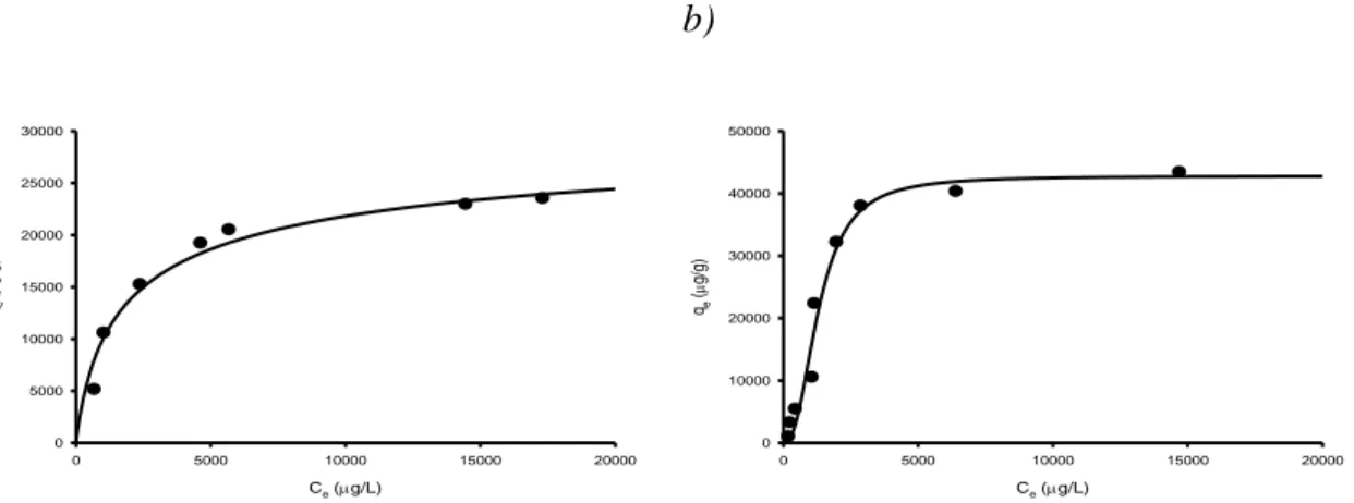
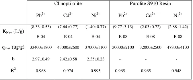
4.4.2 Heavy metal adsorption isotherms: clinoptilolite and Purolite® S910 Resin ... 112
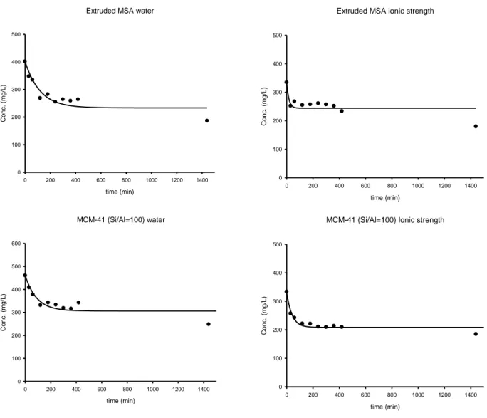
4.4.3 Effect of ionic strength ... 115
4.4.4 Effect of co-contamination: organic compounds ... 118
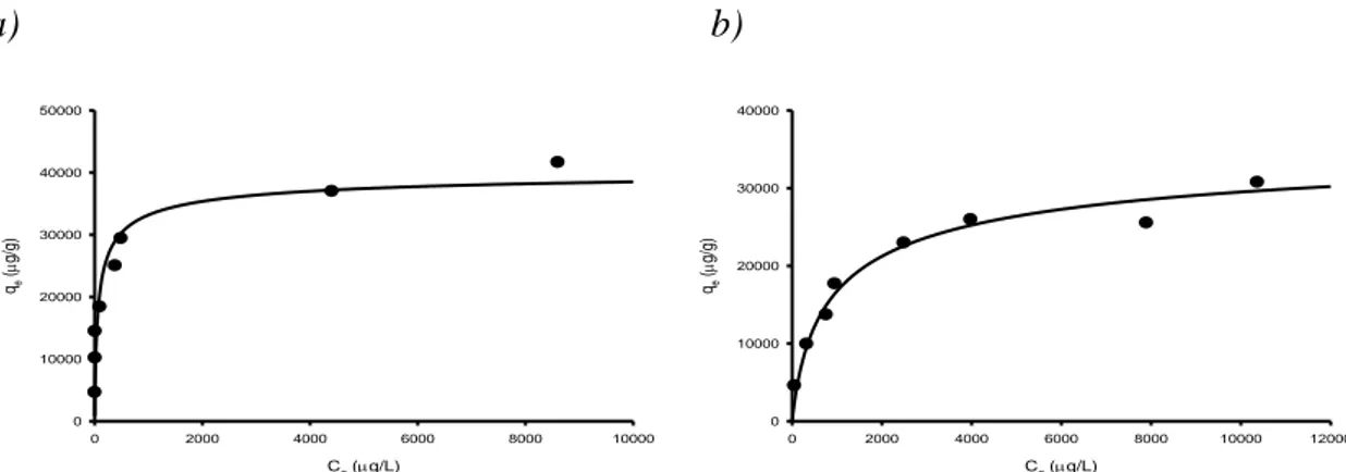
4.4.5 Heavy metal adsorption isotherms: MSA ... 122
4.5 Conclusion ... 123
4.6 References ... 125
CHAPTER 5 ... 135
NEW MATERIAL FOR AROMATIC HYDROCARBONS REMOVAL: BATCH TESTS ... 135
5.1 Materials and methods... 136
5.2 Data evaluation: Kinetic and thermodynamic models ... 138
5.3 Results and discussion ... 141
5.3.1 Pore distribution study ... 141
5.3.2 Kinetic study ... 145 5.3.3 Isotherm study ... 152 5.3.4 Regeneration study ... 161 5.4 Conclusion ... 164 5.5 References ... 166 CHAPTER 6 ... 169
NEW MATERIAL FOR HYDROCARBONS AND HEAVY METALS REMOVAL: ... 169
STRUCTURAL CHARACTERIZATION. ... 169
6.1 Experimental section ... 170
6 6.1.2 Adsorption tests ... 171 6.1.3 SEM ... 172 6.1.4 XRD... 172 6.1.5 FTIR ... 173 6.1.6 Acidity Measurement ... 173 6.1.7 TGA ... 174
6.2 Result and discussion ... 174
6.2.1 SEM ... 174 6.2.2 XRD... 178 6.2.3 FT-IR ... 185 6.2.4 TGA ... 191 6.3 Conclusions ... 195 6.4 References ... 197 CHAPTER 7 ... 199
8
B
ACKGROUND ANDA
IM OF THESISRecovery of waste water is one of the most important challenges for our future due to the endemic scarcity of this resource in many parts of the world. Wastewaters derived from petrochemical activities represent a large share of water linked to human activities. This is due to the centrality of oil for global economy and the great water consumption for all the linked activities that goes from extraction to refinery. In the last decays the sensibility towards this topic arose due to the great world population growth that requires more and more water for drinking usage, agricultural and industrial purposes. From this point of view the sustainability of all those process that involved water consumption has to be guaranteed. Oil extraction and refining is one of those processes that involves huge amount of water that has to be recovered. Dispersed and dissolved hydrocarbons (at high concentration), presence of heavy metals and inorganic ions make very difficult the recovery of oilfield water. Oil wastewater can be divided into two categories: production water linked to phase of oil extraction and process water linked to the refinery’s operations.
During the oil extraction phase, a large amount of waste water is produced. It is naturally present in the deposit rock and extracted with the oil, forming an emulsion. This wastewater is very rich in insoluble and soluble hydrocarbons such as short chain ketones, aldehydes and/or phenols. It is also characterized by high salinity and by the presence of heavy metal ions such as Pb2+, Cd2+, Ni2+, Cr2O72- and VO3+, typical of the
geochemistry of the deposit rock and of the chemical composition of the ancestral organic matter. Several primary treatments, including oil separation, coagulation,
9
flocculation, flotation and filtration have been successfully used to remove oil and suspended solids from produced water. Biological treatments, also known as secondary treatments, should also be considered when these effluents are discharged into natural receiving bodies. For instance, approximately 145 million cubic meters of water were utilized in 2005 in the Canadian state of Alberta for the extraction of oil from oil shale, and in the USA refining operations use approximately 16 million liters of water per year. Concerning this data, it is needful to reuse this waste water at least for the same activities. In addition to the extraction water, another large amount of water is used during the refining activities, the so called process water. This water might be rich in hydrocarbons if it is used in a steam reforming unit or distillation tower, or rich in inorganic and heavy metal ions if it is used in a desalting unit.
The presence of the refineries is linked to the contamination of the groundwater by heavy and light hydrocarbons and sometimes heavy metals. In addition to this, the oil refineries are in many cases located along the coasts, and high salinity of seawater may represent a further problem in the remediation of the contaminated groundwater. Currently the large use of hydrofracking technology is spreading, especially in the USA. This kind of technology is based on the fracturing of the deposit rock to release and collect gas and oil; this is easier than by the traditional methods. Fracking cannot be classified as a “green” process and usually causes the contamination of the groundwater adjacent to the deposit rocks. The use of adsorption technologies to recover waste water for all the petrochemical activities is a very useful technology, especially by using active carbon as the adsorbent material. Active carbon is the traditional adsorbent used for water remediation and can be produced from several vegetable sources, such as coconut shells or cellulosic waste, or more traditional sources, such as carbon and wood. However, its usage has important disadvantages in terms of selectivity and regeneration.
10
The first is a consequence of the aqueous medium in which active carbon has to operate. Water molecules are strong competitors for the active sites of the active carbon, such as the alcoholic and carboxylic ones, and water has the particular ability to drench the carbon pore, preventing the adsorption of contaminants. Regarding selectivity, major problems might be encountered in the remediation of groundwater which can be relatively rich with humic substances. These substances are formidable interfering agents because they are able to interact strongly with the adsorption sites of the activated carbon. Regeneration problems may take place, especially in cases where very high regeneration temperatures are used. In these cases, the high temperature might promote sintering of the material, condensation of the active sites, collapse of the internal structure and consequently a decreasing of the subsurface area with loss of material by burning. Furthermore, if carbon is used with high salinity water, this kind of regeneration does not guarantee the elimination of the adsorbed inorganic ions. To overcome these disadvantages, in the last decades different materials have been developed such as synthetic zeolite, mesoporous materials and the newest MOFs. In particular, the zeolite materials are more stable at high temperature and more selective; moreover, they can be modified with specific ligands to increase selectivity and stability. A process for treatment of wastewater contaminated by organic compounds by adsorption on hydrophobic (siliceous) zeolites has been recently reported. Quite good results have been described in case of dissolved hydrocarbons, while reduced effectiveness has been noticed in presence of oil droplets due to pore clogging. In particular, the mesoporous materials seem to be very effective for hydrocarbon removal both in emulsion and in solution. Their large pore size is more suitable to host large organic molecules, allowing the functionalization of the material with a wide variety of
11
hindered ligands and improving their chemical and physical stability as well as adsorption performances.
From this point of view adsorption technologies providing zeolite materials, both microporous and mesoporous, present a good choice for water remediation due to their simplicity, effectiveness, long term stability and adaptability.
The development of new materials for adsorption technology is the main goal of this thesis. In particular some microporous materials for heavy metals uptake and several mesoporous material for hydrocarbons confinement have been characterized from structural and process point of view. Kinetic and thermodynamic (adsorption isotherms) behaviour of all material with different organic and inorganic pollutants is deeply investigated. Mathematical models to describe adsorption kinetics and isotherms have also been developed in order to obtain important parameter useful for the transaction from bench-scale to the next pilot scale. Structural characterization has been carried out to understand which changes occurred in material structure after adsorption of contaminants, the host-guest interactions and thermal stability of materials. This double characterization work was planned to screen a set of known materials and compare their performances to those of a new mesoporous amorphous material: the mesoporous silica-alumina or MSA. Indeed, the ultimate aim is to use MSA as multitalented material for simultaneous removal of heavy metals and hydrocarbons from wastewater derived from oil extraction, oil refining or oil contamination.
12
C
HAPTER1
WATERANDPETROCHEMICALACTIVITIES
This chapter describes the relationship between water and petrochemical activities, from the extraction phase until the refining of gas and oil. The production water involved in the petrochemical activities can be divided into production water and process water and it represents the largest byproduct of oil production. Because of the importance of water resources on a global scale, water recovery represents nowadays a challenge for future generations.
1.1 Extraction water
The extraction water is the wastewater produced during the extraction of oil from reservoirs. The most is naturally present in the oilfield and its composition is strictly linked to the geological composition of the rocks (also called formation water) (Sauer et al., 1997). Usually, in the underground reservoirs light hydrocarbons are stratified upon the water level and the heavy hydrocarbons are on the bottom, in a way that a mixture of oil and water is present at equilibrium (Viel et al., 2004). The composition of this mixture is function of the inherent solubility of hydrocarbons but a small amount of hydrocarbons is also dispersed in the water as stable oil droplets. Moreover the extraction water has a saline content greater than seawater and a large content of heavy metals, typical of the rock geological composition. Instead, very volatile hydrocarbons form the gas phase in which water vapor could be present. During the extraction phase
13
this vapor can condensate in the pipelines forming a secondary kind of extraction water richer in soluble and volatile hydrocarbons (Ray and Engelhardt, 1992).
The use of water is also increasing exponentially in the recovery of oil from oil sands. Nowadays the relative high cost of crude oil deriving from traditional reservoir makes economically competitive the extraction from sands, even if this latter technique costs a large consumption of water used to extract oil in soil flushing process. The oil extraction from sands is widely used in the Canadian state of Alberta, in which the greater oil sand reservoirs of the world have been estimated (www.api.org). In the neighboring United states of America the largely used technology is the hydrofracking (www.eia.gov). This kind of technology is based on the fracturing of the deposit rock to release and collect gas and oil; this is easier than the traditional technologies but it is not a friendly environmental process because it causes the contamination of the groundwater adjacent to the deposit rocks (EPA report). Rocks are fractured by using pressurized water, often modified by adding chemicals agent to facilitate the rock cracking and the oil lift. Some of these chemicals are very toxic and it is necessary to remove them using specific treatments. In this category of water we can also consider the water used for maintaining the adequate pressure in the wells to facilitate the oil lift. The volume of water used to hold the pressure at high level increases at end of the well life (Stephenson, 1992).
14
1.2 Process water
The process water derives from all the processes that take place to transform the crude oil into refined products, such as fuels, fine chemicals or plastics. In this case the chemical composition of water depends on the specific process in which it is involved. The most large use of water during the transformation of crude oil into fuel or other chemicals is due to the refinery operations (table 1.1). At first, the distillation of crude oil into different fractions requires a lot of water at the top of the distillation column to cool down the outgoing fluids. In addition, water is also required at the bottom of the column to heat at the same time the outgoing fluids. The largest amount of water is spent in this operations and it proportionally increases with the plant dimensions. Water, as cooling or heating fluids, is also used in other operations such as cracking, isomerization, alkylation or reforming. Each of these industrial transformations occur by a catalyst and water is often used to regenerate the catalytic bed; water from this process is characterized by a large amount of hydrocarbons. Also, water is mixed with crude oil in specific units called desalination unit to selectively extract ions from oil. This kind of water is rich of salts and heavy metal cations. However, during the desalination process light and soluble hydrocarbons are also extracted, determining a more diversified water contamination.
15
Process Liters of water/BBL oil
Distillation 98,410
FCC Fluid Catalitic Craking 56,780
Catalityc Reforming 22,710 Alkylation 9,840 desalting 7,950 Visbreaking 7,570 Hydrocraking 7,570 Coking 3,79 Isomerization 3,79 Hydrotreating 3,79
Merox Process Little or none
Table 1.1 Main refinery’s operations and their water consumption.
1.3 Production water characteristics
As mentioned above production water includes both extraction and process water so its chemical and physical characteristics change, depending on its origin. However it is possible to individuate some common features. The presence of oil droplets is essentially due to the high weight hydrocarbon (both aromatic and aliphatic) and their stability is correlated to the superficial tension between water and oil, which depends on
16
the ionic strength, temperature and pH of the aqueous medium (Veil et al, 2004). Generally, the solubility of the organic compounds decreases at the increasing of molecular weight. As a consequence, the soluble organic fraction of produced water is composed only by the low weight compounds: BTEX (benzene, toluene, ethyl-benzene and xylene), alcohols (phenols and methanol), aldheydes and ketons (acetone) and carboxylic acids (volatile fatty acids). Medium weight hydrocarbons (C6 to C15) instead are present only at low concentration. Besides the organic species, also inorganic constituents are present, alkaline cations such as Li+, Na+, K+, Ca2+, Mg2+, Ba2+, Sr2+ and anion like Cl- , SO42-, CO32-, HCO3-. Their distribution in water reflects
the chemical composition of the deposit rocks and they are responsible for the high ionic strength of produced water. Indeed the salinity of produced water might be higher than seawater especially in terms of sodium and chloride concentrations, considering that the total saline concentration of produced water can reach 30.000 mg/l more than the saline concentration of marine environment. Moreover, produced water contains very often heavy metal cations, whose presence depends on the age of the wells and ,also in this case, on the geology of the deposit site. Thus produced water can contain nickel, cadmium, chromium, mercury, silver, copper, lead and zinc at trace levels concentration (Hansen and Davies, 1994). Finally, naturally occurring radioactive materials (NORM) are another constituents of these wastewaters and again their presence is due to the geological formation of the rocks. The most representative radioactive materials ions are radium and barium ions. Heavy metals and NORM are the most toxic constituents of produced water and their removal is difficult to realize, because of the impossibility to transform them in harmless compounds through chemical or physical processes. Production water may also contain solid particles, like sand and silt, that derive from the drilling operations and, in addition to them, some
17
chemical agents such as biocides, corrosion inhibitors, emulsion breakers, antifoam are added to prevent operational problems. All these constituents have to be removed from production water to waste it in accordance with the environmental laws but also to allow its reuse in other applications (Veil et al, 2004).
1.4 Management of produced water
Considering the massive consumption of water by petrochemical activities, its remediation for further purposes is strictly necessary in order to prevent an increasing of its scarcity. The oilfield water is an high contaminated wastewater and it has to be treated for its reuse and recycle or, in the worst condition, for discharging it without environmental contamination. Because of the oil wastewater can be considered like a waste, the same philosophy can be applied to its management. Indeed the reduction of fresh water in all the human activities should be promoted through its recycle in the same productive processes or its reuse in other productive fields. To this purpose the application of remediation technologies is required, in order to obtain the quality standard appropriate to the new use (reuse) or the same original use (recycle). Disposal represents the ultimate chance in a virtuous wastewater management and it can be applied if the known technologies are not able to treat water till the defined environmental standards.
18
1.5 Remediation technologies of produced water
Remediation of produced water is an essential option to realize a good wastewater management. The most important aim of remediation is to transform the potential danger of wastewater into a resource or into an harmless waste. The general activities of operators that treat produced water are as follows:
1. De-oiling: removing dispersed oil and grease, 2. Soluble organics removal,
3. Disinfection,
4. SS removal: removing of suspended particles and sand,
5. Dissolved gas removal: removing of light hydrocarbon gases, carbon dioxide, and hydrogen sulfide,
6. Desalination: removing dissolved salts, 7. Softening: removing excess water hardness, 8. Miscellaneous: removing NORM.
1.5.1 Physical-chemical treatment
This kind of treatments are based on the different physical properties of water and contaminants, i.e. density, solubility, dimension.
19 1.5.2 Adsorption of dissolved organics
This technology is a ripe and spread technologies especially in oilfield wastewater treatment. It involves a porous and sometimes reactive material that is able to adsorb onto both its great surface and its porous the “guest” molecules. Nowadays the most used adsorbent is the activated carbon but the use of other materials such as zeolite, polymers and organoclay materials are spreading (Ali and Gupta, 2007, Ranck J.M. et al., 2005).
Activated carbon can remove soluble BTEX but it has some disadvantages linked to its use in a real remediation context. This material suffers a lot of interferences from molecules that naturally are into the produced or groundwater such as cations or humic and fulvic acids. These substances can react with carboxylic and alcoholic groups on the carbon surface, preventing the adsorption of hydrocarbons contaminant. Another disadvantage occurs during the regeneration process: the wet air oxidation process is not able to guarantee a whole regeneration avoiding the sintering too.
Organoclay is formed by clay, montmorillonite modified with an organic compounds, often a cationic quaternary amine salt. The quaternary cation is exchanged with the natural exchangeable ions present on the negative charge sites of the clay surface. When all the natural ions are replaced by the quaternary ions an organophilic layer cover the clay surface. This layer interacts with the hydrocarbons molecules, removing them from water. Thanks to this characteristic, organoclay can remove also insoluble free hydrocarbons. When organoclay and activated carbon are used together the hydrocarbon concentration decreases below water quality standards (Doyle and Brown, 2000).
20
Polymeric resins are composite material composed of methylmethacrylate (MMA) or styrene and divinylbenzene (DVB) by suspension polymerization. Resins are used especially in heavy metal removal with the adding of chelating and/or exchange groups at the surface. The most common are sulfonic, acetic, amidoxime groups. These sites are not suitable for hydrocarbons adsorption but the co-polymeric matrix is sufficient to support the organic removal. Indeed these copolymers can reduce oil content of produced water to around 85% (Carvalho et al., 2002).
Zeolites can be described as inorganic polymer of tetrahedral SiO4 and Al2O3. Natural
zeolites, such as clinoptilolite, are characterized by ordered crystalline structure that form a channel system of micropores (average channel diameter below 2 nm). The co-presence of Si and Al in the lattice produces a charge imbalance on the zeolite surface. The oxygen atoms are the carrier of the negative charge and they represent the exchange site of the zeolite. The charge imbalance is counterbalanced by little ion as H+, Na+ Mg2+ and Ca2+. Most of the known zeolites have natural origin, but in the last decades a number of new zeolites were synthesized. They are involved in the adsorption of heavy metal cations or ammonium ions in the water softening process. As concerns hydrocarbons adsorption, modified zeolites represent new emerging materials. These particular classes of zeolite are obtained by replacing the counterbalancing ions with big surfactant molecules or quaternary ammonium ions, such as the hexadecyltrimethylammonium (HDTMA) (Ranck J.M. et al., 2005). Surfactant modified zeolites are able to adsorb organic compounds using the interaction between the hydrophobic substituted surfactant and hydrocarbon,s as in the case of organaclays. Modified zeolites by tailoring the internal pore surface with alkyl chains are also successfully used to remove BTEX from saline produced water (Janks and Cadena 1992).
21
Mesoporous materials represent a new class of materials inspired by natural zeolites and synthesized for the first time by the Mobil Oil Corporation researchers in the early 90’s (Charles et al., 1990). They synthesized a new material called M41S. These materials are also composed by silicon, aluminum and oxygen but, unlike zeolites, they can be crystalline or amorphous. In addition, their channel system is formed by pores bigger than the zeolite’s ones. The average diameter of mesoporous materials is included between 2 and 50 nm. They were originally used as catalyst in alkylation, isomerization and cracking of hydrocarbons, thanks to their pore dimensions suitable to host large hydrocarbon molecules. Afterwards they were employed, on a laboratory and pilot scale, as adsorbents for the organic compounds uptake from gaseous and water effluents. Nowadays a lot of mesoporous materials are known and they differentiate each other by the use of different synthetic via and templates. Their family class can be identified with its own acronym:
- Hexagonal Mesoporous Silica (HMS); - Michigan State University (MSU);
- Korea Advanced Institute of Science and Technology (KIT); - Santa Barbara Amorphous (SBA);
- Porous Clay Heterostructure (FSM).
In general the adsorption performances of adsorbents is affected by: • Temperature and pH,
• Suspended oil,
• Low heavy metal concentration and organic–metal complex, • Dissolved contaminants (organic chemicals)
22 • High salinity (Hansen and Davies, 1994).
The use of adsorption technologies is quiet recent but it seems to have a good diffusion due to the simplicity of the equipments and their maintenance.
1.5.3 Membrane filtration
Membrane filtration is a technology which has been developed in the past 2 decades for water and waste water treatment. Membrane filtration systems can be subdivided into four classes: micro filtration (MF) , ultra filtration (UF), nanofiltration (NF) and reverse osmosis (RO), depending on the different dimension of the membrane pores. Micro filtration membranes have the largest pores, UF and NF separate smaller particles and droplets, while RO is able to retain dissolved matter as salts especially in the desalination operation. MF and UF are the most applied in waste water treatment while NF is very rarely applied. RO is used for production of drinking water or boiler feed water from salted water and its use in the waste water treatment is not so spread unless an extensive pre-treatment (MF and/or UF) is applied before RO. The use of NF and RO tout court in the waste water remediation is essentially due to their softness and high cost of maintenance. Indeed NF and RO membranes clog very easily.
Membranes are manufactured of various materials: polymers, such as naphion, cellulose, nylon, PTFE, or ceramics. They can be made of different configurations: tubular or spiral wound membranes or hollow fibers which are fitted in membrane modules. When a membrane is applied to wastewater treatments there is production of a permeate (or cleaned water) and a retentate (in which the contaminants are
23
concentrated). The retentate, which may still contain 98 - 99% water and the majority of pollutants, must be disposed of or treat by different methods. The retentate of a micro-filtration or ultra-micro-filtration unit may constitute 5 - 10% of the waste water flow rate depending on both the type of membranes and composition of the wastewater. Although membrane filtration is able to reduce oil concentration in water up to 5 ppm or less, there is not a massive use of them in wastewater remediation and the development of membranes for these applications is still under investigation. Fouling and poor long term stability are the main problems that affect membrane systems. Indeed in full plant scale membranes must be replaced every 3 - 5 years with high cost of maintenance (Li et al., 2002) Some effective applications were reported by Bilstad and Espedal (Bilstad et al., 2004) comparing MF and UF membranes in pilot trial to treat the North Sea oilfield-produced water. Results showed that UF could reach up the effluent standards for total hydrocarbons, SS and dissolved constituents. Using UF membrane treatment with molecular weight cut-off (MWCO) between 100,000 and 200,000 Da, a reduction of total hydrocarbon concentration up to 2 mg/L from 50 mg/L (96% removal) was observed. Benzene, toluene and xylene (BTX) were reduced up to 54%, and some heavy metals like Cu, and Zn were removed to the extent of 95%. The indicated feed-water specifications for ideal performance of UF were oil and solids less than 50 and 15 ppm, respectively. Ceramic membranes are a new class of materials for the treatment of produced water, Shams Ashaghi et al [Ashaghi et al., 2007, Chen et al., 1991] tested the performances of them to separate oil, grease, and SS from produced water. Permeate quality of dispersed O&G (oil and grease) was 5 mg/L and of SS was less than 1mg/L. The combination system of membrane pretreatment and RO is an effective method for produced water treatment (Burnett, 2004). Xu et al. (Xu et al., 2008) investigated a two stage laboratory-scale membrane for treating gas field produced water from sandstone
24
aquifers. This system was composed of a pretreatment unit of NF followed by an ultra-low-pressure RO unit. It showed the ability to reach up the quality standards for potable and irrigation water and iodide concentration in brine.
1.5.4 Gravity separation
This kind of technologies are used especially to separate the oil droplet or emulsified oil from water using the different density of oil and water.
1.5.5 Retention ponds/Storage pits
By using this technology oil and water are separated into retention ponds/storage pits, where the oil moves up on the surface and the water goes down on the bottom of the ponds or pits. This is a long term operation but it is characterized by low cost maintenance. The oil is spill over the ponds into a near creek. The use of ponds and pits has been replaced by tank provided by a closed valve at the bottom of the tank. From the valve the separated water is spilled out leaving the oil into the tank.
1.5.6 API separator
The API (American Petroleum Institute) separator is one of most used type of oil-water separator in the petrochemical plants. It can remove up to 60 to 99% of the free oil in a waste stream. It works using the different of density between oil and water and the
25
eventual solids. It is constituted by a basin, frequently built of concrete, in which the waste stream is hold for the time necessary to the separation. During this time the lighter compounds go up till the surface where a device for floating scum picks them up out the basin. The heavier compounds and solids are deposited on the bottom where a scraping device removes them as sludge. The purified water and soluble compounds remain inside the basin (American Petroleum Institute) Figure 1.1 shows the schematic of an API oil separator.
26 1.5.7 Skimmer tanks and vessels
The skim (clarifier) tank or vessel is the simplest form of primary treating equipment; showed in Figure 1.2. These items are suitable for long time residence operations in which wastewater is disposal and water and oil are left to separate by gravity and coalescence. Skim tanks can be used as atmospheric tanks, while pressure vessels and surge tanks are different configuration of the same equipment and they are usually employed ahead of other produced water treating equipment (Arnold and Stewart, 2004).
Figure 1.2 Schematic representation of Skimmer tanks and vessels
1.5.8 Plate coalescence
A lot of different types of equipments have been developed to promote, next to the separation by the solely gravity, the coalescence of small dispersed oil droplets. The double effect of gravity and coalescence improves the separation. By using this items is
27
possible to reach the performance of a skimmer in less space . There are various configurations of plate coalescers: parallel plate interceptors (PPI), corrugated plate interceptors (CPI) or cross-flow separators. They differentiate by the way of rising to a plate surface where coalescence and capture occur (American Petroleum institute). The motion of all the oil droplets that enter the space between two following plates is ruled by Stokes’ law. Assuming that the oil droplet has a forward velocity equal to the bulk water velocity and solving for the vertical velocity needed by a particle entering at the bottom of the flow to reach the coalescing plate (at the top of the flow), it is possible to determine the droplet diameter. The most ancient type of plate is the parallel plate interceptors, while nowadays the most used in plant is the corrugated plate interceptors that is a modification of the former. Figure 1.3 shows the flow pattern of a typical down-flow CPI design. In CPIs the parallel plates are corrugated (like roofing material), and the axes of the corrugations are parallel to the flow direction.
28 1.5.9 Enhanced coalescence
To enhance the coalescence of oil droplets a lot of devices have been developed, providing a pretreatment of the effluent to increase the drop dimension and facilitate the subsequential removal.
1.5.10 Mare’s Tail
Tulloch (Tulloch, 2003) describes a pre-coalescer that is made of a bundle of oleophilic polypropylene fibers inside a cartridge set along a flow line just upstream of another separation device (e.g., hydrocyclone, filter). The hydrophobic fibers facilitate the aggregation of the smallest oil droplets for an easier removal during the successive operations. The coalescence occurs rapidly (within two seconds). The name "Mare's Tail" derives from the shape of this device that seems like a horse tail, due to the bundle of polypropylene fibers. Tulloch (Tulloch, 2003) shows that increasing the fiber length or their number in the cartridge the oil droplet growth enhances. Figure 1.4 shows the principle of operation of a Mare’s Tail pre-coalescer.
29
Figure 1.4 Principle of operation of a Mare’s Tail pre-coalescer.
1.5.11 Enhanced gravity separation
To enhance the gravity separation a common way is to apply an external gravitational field to the effluent. In this way the particle deposition and aggregation rate can be greatly enhanced and also the smaller particles can be coalesced. The use of an external gravitational field has the main advantage to get smaller device than the classical ones and the same results can be obtained in shorter time. The two main categories of these technologies are described in the following sections.
30 1.5.12 Hydrocyclones
Hydrocyclones or Static oil-water separator is constituted by a cylindrical chamber in which concentric reducing and taper sections are set. Pressurized oily water enters tangentially through the inlet valve into this cylindrical chamber. At the same time the shape of the chamber and the heater pressure induce a centrifugal rotation motion of the fluid that amplify the effect of gravity during the separation. The centrifugal forces push the lighter oil droplets towards the center of the hydrocyclone where axial flow reversal occurs and the droplets can coalesce and the reject stream is recovered. The clean water instead moves to the wall chamber of the hydrocyclone and is discharged. The total residence time of the effluent in this device is only 2-3 seconds (Bradley, 1990). Hydrocyclones are particularly efficient if the system operates at high pressures by way of its static nature. On the contrary if the system works at low pressure, booster pumps are required for increasing the rate of the inlet effluent. The use of pumps can however induce a shearing action on the oil droplets reducing the system efficiency. Another disadvantage of Hydrocyclones, due to the high pressure, is the high and constant flow rates that are required for its optimum operation. If flow rates are low or variable, a recycle flow stream through a surge tank can be added (Canadian Association of Petroleum Prodducts, 2001). As shown in Figure 1.5, the liner consists of four sections: a cylindrical swirl chamber, a concentric reducing section, a fine tapered section, and a cylindrical tail section (American Petroleum institute).
31
Figure 1. 5 Representation of Hydrocyclone and its main sections.
1.5.13 Centrifuges
Dynamic hydrocyclones are commonly known as centrifuges and they consist of a rotating cylinder chamber, two valves for the axial inlet and outlet, reject nozzle, and external motor (Figure 1.6). The external motor is used to rotate the outer shell of the hydrocyclone in which the effluent is stoked. When the motor is switched, centrifugal rotation motion is transferred to the fluid and the applied rotation creates a “free vortex.” The tangential speed is inversely proportional to the core distance of the cyclone, so that the lighter oil drops are collected in the center and separated from water. Centrifuges have found few applications relative to hydrocyclones because of poor cost–benefit ratio (American Petroleum institute).
32
Figure 1.6 Representation of a typical centrifuge for oil-water separation.
1.5.14 C-tour process
The C-Tour Process was developed by AS company. The C-Tour technology is a liquid-liquid extraction process. In this process, a liquid-liquid condensate is the extract liquid-liquid suitable to remove the dissolved components in produced water. The condensate also helps the coalescing of dispersed oil with small oil droplets, promoting their removal from water. The C-Tour process is carried out through four steps:
- Harvest a suitable condensate stream from production;
- Inject condensate in liquid form into the produced water stream; - Mix and disperse the condensate into the water;
33
- Allow adequate contact time between condensate and water;
- Separate the contaminated condensate from the water in a separation process - Cycle the condensate, containing contaminants, back to the production stream.
It was estimated that this process can remove approximately 70% of dispersed oil and PAHs, as well as up to 70% of phenols (Knudsen et al., 2004). A flow diagram of C-tour processes is given in Figure 11.
34
1.6 Chemical treatment
1.6.1. Chemical precipitation
Gravity separation operations are usually used to remove suspended and colloidal particles, but are not suitable for removing dissolved compounds. Chemical precipitation instead is more suitable for removing these constituents and it requires the addiction of some chemicals to promote the decreasing of their solubility and consequently their precipitation. Lime softening, for example, is the common process for water softening. In the modified hot lime process, produced water containing 2000 ppm hardness, 500 ppm sulfides, 10,000 ppm TDS, and 200 ppm oil could be successfully converted into water with suitable standards for being employed in a boiler. Besides the use of lime, it is possible to add organic and inorganic polymers or polyelectrolyte, a kind of organic polymer that brings some charged center on its chain. Organic polymers, lime, metal hydroxide and salts are called flocculants agents and they have the peculiarity to act as bridge between the colloidal particle and suspended solids. For example FMA is an inorganic mixed metal (Fe, Mg, and Al) polynuclear polymer; it has good coagulation, de-oiling and scale inhibition properties, particularly in produced water with SS levels of 50–400 mg/L. Using FMA is possible to remove SS and oil to levels greater than 92% and 97%, respectively (Zhou et al., 2000). On the other hand, Houcine (Houcine, 2002) showed the high removal efficiency of heavy metals from produced water using a mix of spillsorb, calcite and lime. Moreover, a study concerning the treatment of produced water described the use of ferric ions as oxidant for removing arsenic and mercury, while flocculants were used to remove hydrocarbons. In this process, the oxidation–reduction potential of the wastewater was controlled by adding
35
the required amount of oxidant to allow the arsenic oxidation and the elemental form of mercury. Results showed low levels of contaminants: less than about 10 parts per billion (ppb) of mercury (calculated as Hg), less than about 250 ppb of arsenic (calculated as As), and less than about 40 ppm of TPH (Frankiewicz and Gerlach, 2000). The main disadvantages of the chemical precipitation processes are generation of sludge and the increasing concentration of metals (used as flocculants) in effluents.
1.6.2. Chemical oxidation
Chemical oxidation is the common method for decomposing refractory chemicals in wastewater using strong oxidant, catalysts, and irradiation (except ozone treatment) (Renou et al., 2002).
1.6.3 Electrochemical process
The electrochemical process for remediation of oilfield wastewater is still under study and only few laboratory tests have been performed in these last years. One of them is reported by (Ma et al., 2006) that showed a laboratory pilot-scale plant composed by double anodes with active metal, graphite and iron, and a noble metal content crystal with a large surface as cathode. Results showed the reduction of the COD and BOD of oilfield produced water by over 90% during the first 6 minutes of activity.
36 1.6.4 Photocatalytic treatment
Photocatalytic treatment born as a modification of the use of TiO2 electrodes, usually
employed for the photo-electrochemical decomposition of water to produced H2
(Fujishima and Honda, 1972). There is not an industrial application of this device and only laboratory scale tests have been performed. This method can be used for different pollutants. The general process for organic pollutant treatment by photocatalytic method is :
organic pollutant + O2 semiconductor, hv CO2 + H2O + mineral acids
The interaction of light photon and TiO2 semiconductor produces an electron streams
that starts the oxidation reaction of organic pollutant with oxygen. The most proposed process for oilfield-produced water treatment by photocatalytic method includes a prior process of clarification by adding soda up to pH 11 and a successive filtration. The photocatalytic process is then applied to the clarified wastewater. Photocatalytic reaction was carried out in an open reactor to ensure the required amount of oxygen and the adequate amount of photcatalyst-TiO2 is added. A high-pressure 250W mercury
lamp illuminated the suspension at 298K starting the decomposition reaction. This method could reduce toxicity of produced water (Bessa et al., 2001). Li et al. (Li et al, 2006; Li et al., 2007) performed a study about the reduction of toxicity and COD removal efficiency, comparing the results to those of photo-catalysis and electrochemical oxidation. Results showed a COD removal by photoelectron-catalytic process much higher than by photo-catalytic or electrochemical oxidation. The same study showed that at equivalent doses, photoelectron-catalysis has the best performance
37
of reducing genotoxicity, whereas photo-catalysis is the least effective and do not lead significative change in mutagenicity. So the photoelectron-catalysis system seem to be the most effective technology for degradation of oilfield wastewater. In a similar study, (Adams et al. 2008) utilized a drum reactor with a single pass continuous-flow system for produced water effluents. In this reactor, titanium metal was used as substrate. The reactor drums were irradiated using sunlamp UV tubes. Results showed that hydrocarbon content could be reduced by more than 90% in 10 minutes.
1.6.5. Fenton process
Fenton process is a combined process in which flocculation, oxidation and adsorption occur in series reactors. The first phase is the flocculation in which poly-ferric sulfate was used as flocculant agent for a 30-minutes settling period. In the second reactor the oxidation reaction occurs at pH 3–4 by an oxidant aqueous solution of 30% H2O2 and
4% of Fe3+ for an oxidation time of 120 minutes. Finally, the third stage provides the use of active carbon as adsorbent in a batch process in which the active carbon is added up to the concentration of 4000–5000 mg/L and an adsorption time of 120 minutes is used (Yang and Zhang, 2005)
38 1.6.6. Treatment with ozone
This technology provides the use of ozone gas as oxidizing agent. In this case after the reaction the ozone becomes oxygen and this is the main advantage of this process: the absence of secondary toxic products. The use of ozonolysis is a very new technology and it is still in its laboratory research phase. However Morrow et al. (Morrow et al., 1999) proposed ozonolysis for decomposing dissolved organic compounds in produced water. Klasson et al. (Klasson et al., 2002) compared destruction of soluble organics by sono-chemical oxidation and ozonolysis using a sample of synthetic and real produced water. Sono-chemical oxidation could remove some compounds such as BTEX, but the combination of ozone and hydrogen peroxide did not improve the decomposition of organics to CO2. Their experiment showed that the use of ozone is able to remove only
the extractable organics within 3 days of working. This results underlined the low efficiency of this process and in addition the need to consider the high running costs due to the high demand of energy and chemicals.
1.7 Biological treatment
Biological treatment are characterized by the use of aerobic and anaerobic microorganisms. In aerobic treatment, activated sludge, trickling filters, sequencing batch reactors (SBRs), chemostate reactors, biological aerated filter (BAF), and lagoons are used. Four sources of microorganisms were studied and applied in biological treatment:
39 • Naturally occurring microorganisms, • Commercial microorganisms,
• Specific groups of microorganisms, • Acclimated sewage sludge.
Generally, activated sludge is the common method for treating wastewater. As other methods, biological treatments need to have a pretreated wastewater before operating the oil removal. For example, in a continuous-flow pilot plant an oil skimmer was set before the biological reactor to remove oil before treatment by activated sludge system. It was studied the operational efficiency of an activated sludge treatment unit that could maintain a total petroleum hydrocarbon (TPH) removal efficiency of 98–99% at a Solids Retention Time (SRT) of 20 days [3]. Freire et al. also (Freire et al., 2001) studied the ability of acclimated sewage sludge to remove COD from oilfield water using Sequencing Batch Reactor (SBR) with different percentages of produced water and sewage. In 45% and 35% (v/v) mixtures of wastewater, it was found a COD removal efficiency variable from 30% to 50%. Another study instead moved the attention from the COD to TOC removal using acclimated microorganisms in 180 mg/L NaCl. This study was carried out on three different biological systems including SBR, trickling filters and chemostate reactors and the operational conditions of each system was reported below:
• 2 L SBR with 24-h cycle (1 h for feed, 20 h for reaction, 2 h for settling, and 1 h for withdrawal).
40
• A trickling filter equipped with annular plastic supports with packing volume of 1.7 L and hydraulic load of 3 m3/m2 h.
• A 1L chemostate reactor with 8 days hydraulic retention time.
Even if SBR could cause a major loss of biomass, its removal efficiency (in terms of TOC) was higher than that of the trickling filter and of the chemostate (Baldoni et al., 2006).
Due to high salt concentration of wastewater it is possible to have depressive effect on the biomass activity. However Freire et al. found significant effect of only recalcitrant organic compounds on COD removal of mixed wastewater, while salinity seemed to not have affected biological treatment; also, Wei et al. (Wei et al., 2003) showed that inhibitory effect of the high salinity on composite microbial culture was negligible if Cl− concentration was increased from 2000 to 36000 mg/L. Nevertheless, another study conducted by Dfaz et al. (Dfaz et al., 2000) showed that an increase of salinity up to 100,000 mg/L produced a dramatic decrease of biodegradation rate, because high concentration of sodium chloride causes environmental stress and microbial lysing effects (Tellez and Nirmalakhandan, 1992). In addition to this, salinity can lead both to a reduction of filamentous bacteria and the integrity of the flocks with a consequent increasing of the treated water turbidity (Lefebvre and Moletta, 2006) For improving biological treatment of effluent, membranes can be coupled to it Kang et al., 2003). Palmer et al. (Palmer et al., 1981) studied the treatment of oilfield-produced water using rotating surfaces covered of biofilm (biodisks). This biodisks were populated by bacterial sludge derived from sewage treatment plant. This kind of device is able to
41
remove BOD and O&G of 94% and 74%, respectively. Besides, immobilization of microorganisms can increase the treatment efficiency.
Li et al. (Li et al., 2005) studied the removal of COD of oilfield-produced water using Bacillus sp. (M-12) immobilized on polyvinyl alcohol (PVA). Bacillus sp. can achieved more than 90% efficiency of COD removal with initial COD of 2600 mg/L. Zhao et al. (Zhao et al., 2006) instead explored use of commercial microorganisms immobilized on poly-ammoniacum carriers. For this purpose a pair of BAF reactors was realized. Results showed that this microbial consortium can degrade TOC and oil of produced water of 78% and 94% respectively, with a hydraulic retention time of 4 hours and volumetric load 1.07 kg COD/(m3day). Different microorganism such as, harmless bacteria, algae, fungi and protozoa, can convert through biological oxidation dissolved organics into water and CO2, and ammonia into nitrates/nitrites (Palmer et al., 1981),
but have no effect on TDS (Jackson et al., 2003). Beyer et al. (Beyer et al., 1979) studied a complex reactor composed of two-stage pilot lagoon of 80 m3 placed in series and consisting of plastic-lined steel tanks, each filled with 60 m3 of fluid. Each tank had a different task: the first was for oxidizing suspended oil and dissolved organics and the second lagoon was for oxidizing dissolved ammonia compounds
In biological treatment the mainly mechanism of dissolved hydrocarbon removal is the biodegradation, while dispersed hydrocarbons and particles are removed by a mechanism similar to bio-flocculation. Indeed, activated sludge can adsorb and occlude not only soluble but also insoluble materials. Bacteria can produce compounds such as surfactants (bio-surfactants) and emulsifiers (bio-emulsifiers) that are surface-active compounds able to enhance the solubility of hydrocarbons and thence improve their mass transfer from the bulk to the biodegrading bacteria (Hommel, 1990). Not all the organics and hydrocarbons are biodegradable, their biodegradability is directly
42
proportional to their structure simplicity, e.g., normal alkanes is easier than of branched and large molecules. The bio-recalcitrant molecules are removed along with sludge because they are adsorbed onto the bacterial surface or incorporated within the sludge flock. The mixture of hydrocarbons and microorganisms obtained after the biological treatment is classified as hazardous waste and it has to be disposed.
Aerobic biological treatment are not the only applicable biological treatment, especially when raw wastewater is concentrated in terms of organic compounds, anaerobic degradation of contaminants could be a good alternative to aerobic process (Metcalf, 2003) Gallagher (Gallagher, 2001) studied the bio-removal of organic acids in synthetic produced water in the presence of naphthenic acids under anaerobic conditions. The microbial consortium used for this experimentation derived from a sludge used in a anaerobic digester of a municipal treatment system. Results showed that anaerobic microorganism could not degrade naphthenic acids. Another study (Gurden and Cramwinckel, 2000) concerned the bioremediation approach to remove hydrocarbons and heavy metals from wastewater using an 800 m2 reed bed with Phragmites australis. Results showed that more than 98% of hydrocarbons were biodegraded. Al Mahruki and Alloway (Al Mahruki and Alloway, 2006) studied a similar pilot plant, operating the reduction of total hydrocarbons and heavy metal concentration on 3000 m3/day of produced water. The reduction of hydrocarbons was of 96% while metal concentration decreased up to 78% for Al, Ba, Cr, Cu, and Zn, up to 40% for Fe, Li, Mn, Pb, As, Cd, Co, Mo, Ni, Se, Tl, and V. Although this system is a cost-effective method, the effluent has to be refined and requires a lot of land.
43
1.8 References
Adams M. , Campbell I., Robertson P.K.J., Novel photocatalytic reactor development for removal of hydrocarbons from water, Int. J. Photoenergy (2008) 1–6,Art. No. 674537.
Al Mahruki A. , Alloway B., The use of reed-bed technology for treating oilproduction waters in the sultanate of Oman, in: SPE International Health, Safety & Environment Conference, Abu Dhabi, UAE, 2–4 April, 2006.
Ali Imran and Gupta V. K., Advances in water treatment by adsorption technology. Nature Protocols 1, 2661 - 2667 (2007)
American Petroleum Institute (API), 1990. Monographs on Refinery Environmental Control Management of Water Discharges (Design and Operation of Oil-Water Separators).Publication 421, First Edition.
Arnold, K.E. Stewart, M., Surface production operations-Design of Oil Handling Systems and Facilities, vol. 1, third ed., Gulf Publishing Co, Houston,Texas, 2008.
Arthur J.D. , Langhus B.G., Patel C., Technical Summary of Oil and Gas Produced Water Treatment Technologies,
http://www.rrc.state.tx.us/commissioners/williams/environment/producedwatertrtmntTe ch.pdf,2005.
Baldoni-Andrey P. , Lesage N., Segues B., Pedenaud P., Dehaene P.L., Impact of high salinity of producedwater on the technical feasibility of biotreatment for E&P onshore applications, in: SPE International Health, Safety & Environment Conference, Abu Dhabi, UAE, 2–4 April, 2006.
44
Bessa E. , Sant’Anna G.L. Jr., Dezotti M., Photocatalytic/H2O2 treatment of oil field
produced waters, Appl. Catal. B 29 (2001) 125–134.
Beyer A.H. , Palmer L.L., Stock J., Biological oxidation of dissolved compounds in oilfield-produced water by a pilot aerated lagoon, JPT J. Petrol. Technol. 31 (1979) 241–245.
Bilstad T. , Madland M., Espedal E.and Hanssen P. H., Membrane Separation of Raw and Anaerobically Digested Pig Manure Water Science & Technology Vol 25 No 10 pp 19–26 © IWA Publishing 1992
Bradley B.W., Produced water treatment technology assessment. Prepared for the American Petroleum Institute-Offshore effluent guidelines steering committee, Washington, DC, 1990.
Burnett, D.B., 2004. Potential for Beneficial Use of Oil and Gas Produced Water, http://www.rrc.state.tx.us/commissioners/williams/environment/ beneficialuses.pdf.
CAPP, 2001. Produced water waste management, Technical report, Canadian Association of Petroleum Products (CAPP), page 9.
Carvalho M.S. , Clarisse M.D., Lucas E.F., Barbosa C.C.R., Evaluation of the polymeric materials (DVB copolymers) for produced water treatment, in: SPE International Petroleum Exhibition and Conference, Abu Dhabi, UAE, 13–16 October, 2002.
Charles T. Kresge, Michael E. Leonowicz, Wieslaw J. Roth, James C. Vartuli Inorganic oxides as an absorbent and for catalytic conversion of inorganic and organic compounds US 5098684 A 1990
45
Chen, A.S.C., Flynn, J.T. , Cook, R.G. , Casaday, A.L.,1991.Removal of oil, grease,and suspended solids from produced water with ceramic crossflow microfiltration,SPE Prod. Eng. 6 (1991) 131–136.
Dfaz M.P. , Grigson S.J.W., Peppiat C.J., Burgess G., Isolation and characterization of novel hydrocarbon-degrading euryhaline consortia from crude oil and mangrove sediments, Mar. Biotechnol. 2 (2000) 522–532.
Doyle D.H. , Brown A.B., Produced Water treatment and hydrocarbon removal with organoclay, in: SPE Annual Technical Conference and Exhibition, Dallas, Texas, USA, 1–4 October, 2000.
Environment Canada Website www.ec.gc.ca/water/en/manage/use/e_wuse.htm
EPA report “The Potential Impacts of Hydraulic Fracturing on Drinking Water Resources”. (2012)
Frankiewicz T.C., Gerlach J., Removal of hydrocarbons, mercury and arsenic from oil-field produced water, US Patent No. 6,117,333 (2000).
Freire D.D.C. , Cammarota M.C., Sant’Anna G.L., Biological treatment of oil field wastewater in a sequencing batch reactor, Environ. Technol. 22 (2001) 1125–1135.
Gallagher J.R., Anaerobic Biological Treatment Of Produced Water,
http://www.energystorm.us/AnaerobicBiologicalTreatmentOfProducedWater-r54822.html, 2001.
Gurden C., Cramwinckel J., Application of reedbed technology in production water management, in: SPE International Conference on Health, Safety and Environment in Oil and Gas Exploration and Production, Stavanger, Norway, 26–28 June, 2000.
46
Hansen BR, Davies SR., Review of Potential Technologies for the Removal of Dissolved Components from Produced Chemical Engineering Research & Design, Vol.72, No.2, 176-188, 1994
Hommel R.K., Formation and physiological role of bio-surfactants produced by hydrocarbon-utilizing microorganisms, Biodegradation 1 (1990) 107–119.
Houcine M. , Solution for heavy metals decontamination in produced water/case study in southern Tunisia, in: International Conference on Health, Safety and Environment in Oil and Gas Exploration and Production, Kuala Lumpur, Malaysia, 20–22 March, 2002.
Jackson L.M. , Myers J.E., Design and construction of pilot wetlands for produced-water treatment, in: SPE Annual Technical Conference and Exhibition Denver, Colorado, USA, 5–8 October, 2003.
Janks J.S., Cadena F., Investigations into the use of modified zeolites for removing benzenes, toluene and xylene from saline produced water, in: J.P. Ray, F.R.Engelhardt (Eds.), Produced Water: Technological/Environmental Issues and Solutions, Plenum Publishing Corp., New York, 1992, pp. 473–488.
Kang I.J. , Lee C.H., Kim K.J., Characteristics of microfiltration membranes in a membrane coupled sequencing batch reactor system, Water Res. 37 (2003) 1192–1197.
Klasson K.T., Tsouris C., Jones S.A., Dinsmore M.D., Walker A.B., De Paoli D.W., Yiacoumi S., Vithayaveroj V., Counce R.M., Robinson S.M., Ozone Treatment of Soluble Organics in Produced Water, http://www.osti.gov/bridge, 2002.
Knudsen B.L., Hjelsvold M., Frost,T.K., Svarstad M.B.E., Grini, P.G., Willumsen C.F., Torvik, H. Meeting the zero discharge challenge for produced water. paper SPE 86671,
47
presented at the seventh SPE International Conference on Health, Safety, and Environment in Oil and Gas Exploration and Production held in Calgary, Alberta, Canada, 29–31 March 2004.
Lefebvre O. , Moletta R., Treatment of organic pollution in industrial saline wastewater: a literature review, Water Res. 40 (2006) 3671–3682.
Li Q. , Kang C., Zhang C., Waste water produced from an oilfield and continuous treatment with an oil-degrading bacterium, Process Biochem. 40 (2005) 873–877.
Li G., An T., Chen J., Sheng G., Fu J., Chen F., Zhang S., Zhao H., Photoelectrocatalytic decontamination of oilfield producedwastewater containing refractory organic pollutants in the presence of high concentration of chloride ions, J. Hazard. Mater. B138 (2006) 392–40
Li G., An T., Nie X., Sheng G., Zeng X., Fu J., Lin Z., Zeng E.Y., Mutagenicity assessment of produced water during photo-electro-catalytic degradation, Environ. Toxicol. Chem. 26 (2007) 416–423.
Li L.B. , Yan S., Zeng X.D., Lin D.Q., Analysis of organic compounds in oilfield produced water, Petrochem. Technol. 31 (2002) 472–475.
Ma H. , Wang B., Electrochemical pilot-scale plant for oil field produced wastewater by M/C/Fe electrodes for injection, J. Hazard. Mater. B132 (2006) 237–243.
Metcalf, Eddy, Wastewater Engineering: Treatment and Reuse, 4th ed., McGraw-Hill Inc., New York, 2003.
Morrow L.R. , Martir W.K., Aghazeynali H., Wright D.E., Process of treatingproduced water with ozone, US Patent No. 5,868,945 (1999).
48
Palmer L.L. , Beyer A.H., Stock J., Biological oxidation of dissolved compounds in oilfield produced water by a field pilot biodisk, J. Petrol. Technol. 8308-PA (1981) 1136–1140.
Ranck, J., Bowman, R., Weeber, J., Katz, L., and Sullivan, E. (2005). ”BTEX Removal from Produced Water Using Surfactant-Modified Zeolite.” J. Environ. Eng., 131(3), 434–442.
Ray J.P., Engelhardt F.R.,Produced Water–Technological/Environmental Issues and Solutions (1992)., Eds.;Plenum Press,New York & London.
Renou S., Givaudan J.G., Poulain S., Dirassouyan F., Moulin P., Landfill leachate treatment: review and opportunity, J. Hazard. Mater. 150 (2008) 468–493.
Sauer TC, Costa HJ, Brown J, Sand Ward TJ, (1997).Toxicity Identification Evaluations of Produced Water. Environmental Toxicology and Chemistry 16(10):2020 – 2028.
Shams Ashaghi, K., Ebrahimi, M., Czermak, P.,2007.Ceramic ultra- and nanofiltration membranes for oilfield produced water treatment: a mini review, Open Environ. J. 1 (2007) 1–8.
Stephenson MT (1992).Components of Produced Water:A Compilation of Industry Studies.Society of Petroleum Engineers May 1992:548–603.
Tellez G.T. , Nirmalakhandan N., Bioreclamation of oilfield produced wastewaters: characterization and feasibility study, in: J.P. Ray, F.R. Engelhardt (Eds.), ProducedWater: Technological/Environmental Issues and Solutions, Plenum Publishing Corp., New York, 1992, pp. 523–534.
49
Tulloch, S.J., 2003. "Development & Field Use of the Mare's Tail® Pre-Coalescer,"presented at the Produced Water Workshop, Aberdeen, Scotland, March 26-27.
US Energy Information administration: www.eia.gov
Veil J. , Puder M.G., Elcock D., Redweik R.J.J., A White Paper Describing Produced Water from Production of Crude Oil, Natural Gas and Coal BedMethane,2004.
Wei N. , Wang X.H., Li F.K., Y.J. Zhang, Guo Y., Treatment of high-salt oil field produced water by composite microbial culture, Urban Environ. Urban Ecol.16 (2003) 10–12.
Xu P., Drewes J.E., Heil D., Beneficial use of co-produced water through membrane treatment: technical-economic assessment, Desalination (2008) 225, pp.139–155.
Yang Z.G. , Zhang N.S., Treatment of produced wastewater by flocculation settlement-Fenton oxidation–adsorption method, Nat. Sci. Ed. 20 (2005) 50–53.
Zhao X., Wang Y., Z. Ye, Borthwick A.G.L., Ni J., Oil field wastewater treatment in biological aerated filter by immobilized microorganisms, Process Biochem. 41 (2006) 1475–1483.
Zhou F.S. , Zhao M.F., Ni W.X., Dang Y.S., Pu C.S., Lu F.J., Inorganic polymeric flocculent FMA for purifying oilfield produced water: preparation and uses, Oilfield Chem. 17 (2000) 256–259
50
Chapter 2
THE ADSORPTION PROCESS
The term “adsorption” refers to a physic-chemical phenomenon that occurs between gaseous or liquid molecules and the solid surface of a material. For gaseous compounds it is possible to distinguish between two different kind of adsorption, depending on the involved energy and the specificity of the mechanism: physisorption or chemisorption. Physisorption is a non-specific adsorption and it takes places between the material surface and fluid molecules. It is possible to imagine this kind of adsorption as the liquefaction of gaseous molecules onto the material surface (Oura et al., 2003). On the contrary, chemisorption involves the interactions between molecules and some specific points of the material surface called active sites. The adsorption proceeds with the break of the molecular bonds and the formation of new ones between the originated atoms and the superficial active sites (Oura et al., 2003). In particular, when the liquid compounds are considered, the classification of the adsorption process is done considering the typology of the interaction between adsorbate (liquid molecules) and adsorbent (solid material). For ionic species, electrostatic interactions occur among ions and the ionic exchangeable sites of the adsorbent. In this case a counter-ion desorbs from the site towards the external, leaving free its position for the adsorbing ion; this ionic exchange position takes place simultaneously. If the material surface is devoid of ionic exchange
51
sites but rich in other kind of sites, such as complexation or chelating sites, a superficial complexation between ions and these sites occurs. The most common complexation sites are hydroxyl, thiol and amino groups. Usually, different complexation groups can be joined in a unique group called chelating group (Fenglian and Qi, 2011). Chelating groups are typical of polymeric and, in general, of synthetic materials such as chelating resins and adsorbent polymers. Ionic exchange and surface complexation are typical adsorption mechanisms of inorganic ionic species. As concerns organic compounds instead, they are involved in different mechanisms of adsorption. The typical interactions between this class of compounds and material surface are Wan der Waals and London forces. The same interactions also occur between adsorbed molecules and free molecules promoting the adsorption of the latter (Parida et al., 2006)
Considerations about the typology of mechanism regulating the interactions between adsorbent and adsorbate are relevant to the microscopic environment.
Focusing the attention on the macroscopic level the selectivity of the adsorption process can be described by three distinct mechanisms: steric, equilibrium and kinetic. In the steric mechanism, the porous structure of the solid material operates a selection of molecules based on their different dimensions. Large molecules cannot enter the pores, because of their lack of a suitable diameter, while the smaller ones can penetrate pores and they are sieved from the bulk environment.
The equilibrium mechanism is based on the thermodynamic properties of solid surface to attract and bond the different species. In this way, the molecules that adsorbs with the strongest interactions are also the species preferentially removed by the solid. In other words, the affinity between adsorbate and adsorbent regulates the adsorption process.