S
CIENZA DEI
M
ATERIALI E
N
ANOTECNOLOGIE
-
XXIX
CICLO
M
ARIANNA
G
AMBINO
STRUCTURAL STUDY, COMPUTATIONAL ANALYSIS
AND STRUCTURE-PROPERTY CORRELATIONS IN
ANION CONDUCTING ELECTROLYTES FOR
SOLID OXIDE FUEL CELLS
TUTOR:PROF.ANTONINO MARTORANA
CO-TUTOR:DR.FRANCESCO GIANNICI
COORDINATORE:PROF.MARIA GRAZIA GRIMALDI
TESI PER IL CONSEGUIMENTO DEL TITOLO DI DOTTORE DI RICERCA
UNIVERSITÀ DEGLI STUDI DI CATANIA
UNIVERSITÀ DEGLI STUDI DI PALERMO
IN CONVENZIONE CON“The very basic core of a man’s living spirit is his passion for adventure. The joy of life comes from our encounters with new experiences and hence there is no greater joy than to have an endlessly changing horizon, for each day to have a new and different sun.”
Abstract
A combined experimental and theoretical approach has been used in order to investigate the local structural features that have an influence on ionic conductivity of IT-SOFC (Intermediate Temperature Solid Oxide Fuel Cell) electrolytes, in order to link the properties of these materials with their atomic and electronic structure.
Doped δ-Bi2O3 and LaGaO3 electrolytes for AC-SOFC applications have been studied as
model compounds for oxygen-ion diffusion in fluorite-like and perovskite-like materials, due to their incredibly high anion conductivity. A combined X-Ray Absorption Spectroscopy (XAS) and Density Functional Theory (DFT) study has been carried out with the aim to unveil the role of the dopants on the short range structure of these materials, to probe the preferential association of vacancies with both dopant and regular site cations, and to highlight the preferential oxygen-ion diffusion paths. This could help to define criteria for the design of new materials with improved properties.
The influence of the electrode-electrolyte interface on the overall fuel cell ionic conductivity has been also addressed. To this aim, a novel protocol to evaluate electrode-electrolyte compatibility through Scanning X-Ray Microscopy (SXM) has been developed and cation interdiffusion has been successfully probed at the interface between some electrolyte-cathode couples.
Abstract
Il presente lavoro propone lo studio di elettroliti ceramici per IT-SOFC (Intermediate Temperature Solid Oxide Fuel Cell). In particolare, lo scopo della tesi è analizzare le caratteristiche strutturali a corto raggio aventi un’influenza sulla conducibilità ionica del materiale, al fine di collegare le proprietà degli elettroliti in esame con la loro struttura atomica ed elettronica.
Gli elettroliti a conduzione anionica studiati sono la fase δ dell’ossido di bismuto (δ-Bi2O3) e
il lantanio gallato (LaGaO3). Data la loro elevatissima conducibilità anionica, tali materiali
sono stati scelti come composti modello attraverso cui descrivere la diffusione di ioni ossigeno in elettroliti a struttura fluoritica e perovskitica. Il ruolo dei droganti sulla struttura a corto raggio di tali materiali è stata indagata mediante l’utilizzo combinato della X-Ray Absorption Spectroscopy (XAS) e della Density Functional Theory (DFT), allo scopo di svelare l’associazione preferenziale delle vacanze con i cationi (droganti e cationi del sito regolare) e individuare i cammini di diffusione dello ione ossigeno favoriti. Tali informazioni possono essere utilizzate nella definizione di criteri per la progettazione di nuovi materiali con migliorate proprietà.
Nel presente lavoro è stata inoltre studiata l’influenza dell’interfaccia elettrodo/elettrolita sulla conducibilità ionica complessiva della cella a combustibile. A tal fine, è stato sviluppato un nuovo protocollo per la valutazione della compatibilità elettrodo/elettrolita mediante Scanning X-Ray Microscopy (SXM) e l’interdiffusione cationica è stata rilevata con successo in alcune coppie catodo/elettrolita precedentemente sottoposte alle temperature operative della cella.
CHAPTER 1: Introduction
1. Solid Oxide Fuel Cells 1
1.1 Energy production and environment 1
Environmental scenario 1
SOFC: an open challenge for market and for materials science 2
1.2 SOFC devices and materials 3
SOFC working scheme 3
SOFC materials 4
2. Electrolytes for AC-SOFC 11
2.1 Fluorite-type and perovskite-type electrolytes. 11
2.2 δ-Bi2O3 13
α, β, γ and δ Bi2O3 14
δ-Bi2O3: oxygen-ion sub lattice model for vacancy arrangement 15
Dopant effect on δ-Bi2O3 stabilization 16
Ta-doped Bi2O3 18
2.3 LaGaO3 20
Dopant and co-dopant effect on the ionic conductivity 21
Structural effect of A-site and B-site substitution 22
Vacancy interaction with B-site cations 23
Oxygen-ion diffusion mechanism 24
Cobalt co-doping on Mg B-site 25
3. Cation interdiffusion at electrode-electrolyte interface 26
3.1 Electrode-electrolyte compatibility 26
ii
4. Objectives 28
5. References 30
CHAPTER 2: Theoretical Background
1. X-Ray Absorption Spectroscopy 41
1.1 X-Ray Absorption 44 Golden rule 44 One-electron approximation 45 Dipole approximation 46 Sudden approximation 46 De-excitation mechanism 47
1.2 The EXAFS function 48
Monoatomic system 48
Biatomic system 49
Polyatomic system 51
Inelastic effects 51
Multiple Scattering effects 52
Disorder effects 53
1.3 Experimental setup 53
1.4 Data analysis 55
GNXAS and FEFF 57
2. X-Ray Microscopy 59
2.1 Experimental setup 61
3. Density Functional Theory 62
CRYSTAL code 67
4. References 68
CHAPTER 3: XAS and DFT study of Bi1-xTaxO1.5+x electrolytes
1. Motivation of the study 71
2. Experimental and computational methods 72
3. Results and discussion 73
3.1 X-Ray Absorption Near Edge Structure 73
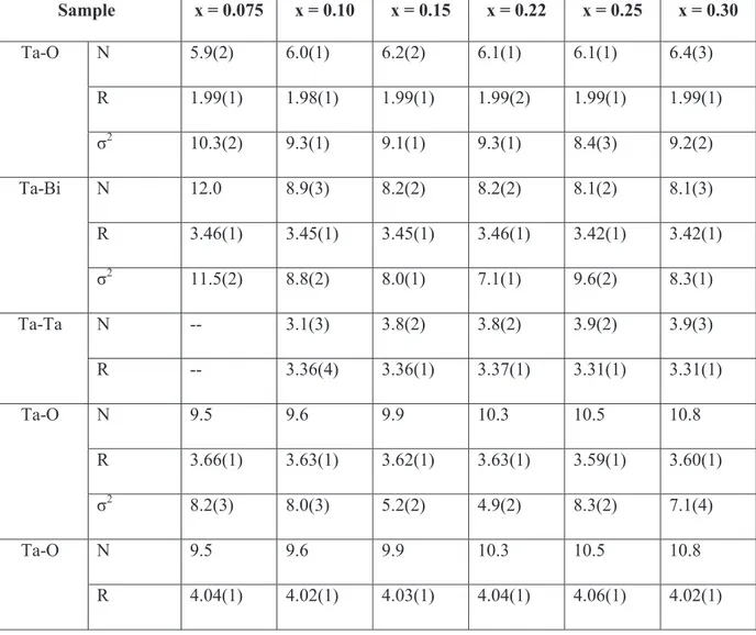
3.2 Extended X-Ray Absorption Fine 74
Ta L3-edge 74
Bi L3-edge 76
3.3 Density Functional Theory 81
Geometry optimization 81
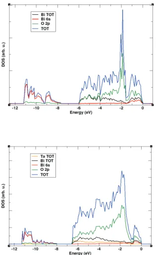
Density of States 83
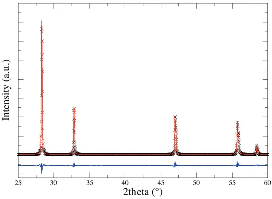
3.4 X-Ray Diffraction 84
3.5 Properties of V- and Nb-doped bismuth oxide 85
4. Conclusions 87
5. References 88
CHAPTER 4: XAS and DFT investigation on doped LaGaO3
1. Motivation of the study 93
2. Experimental and computational methods 95
3. Results and discussion 96
3.1 Defect interaction and local structural distortion
in LaGa0.875Mg0.125O2.93 96
iv
Configurational analysis by Symmetry Independent Classes (SIC) 99
Local structure distortions 102
Square pyramidal MO5Vo site 106
Tilting and dihedral distortions 107
Electronic structure 108
3.2 Oxygen-ion diffusion paths in LaGa0.875Mg0.125O2.93 112
3.3 Effect of doping and co-doping on LaGaO3
perovskite-like structure 115
4. Conclusions 122
5. References 123
CHAPTER 5: Probing electrode-electrolyte interfaces by SXM
1. Motivation of the study 128
The LNC-LSM couple 129
2. Experimental methods 130
3. Results and discussion 131
3.1 μ-XRF: La L3-edge 131
3.2 μ-EXAFS: Mn K-edge 133
3.3 μ-XANES: Nb L3-edge 135
3.4 SXM analysis of the interfaces SDC-LSCF and SDC-LSM 136
4. Conclusions 138
5. References 139
CONCLUSIONS 141
S.1 SUPPORTING INFORMATION
S.2 SUPPORTING INFORMATION
XAS and DFT investigation on doped LaGaO3 155
S.3 SUPPORTING INFORMATION
Probing electrode-electrolyte interfaces by SXM 176
Curriculum Vitae 182
1
CHAPTER 1
Introduction
The purpose of this chapter is to draw a general overview of the state of the art of IT-SOFC technology and to contextualize the role of this devices in the development of novel clean power production strategies. A detailed description of the electrolyte materials studied in this work will be given and a novel method to probe electrode-electrolyte compatibility will be presented. Finally, the objectives of the thesis will be drawn.
1. Solid Oxide Fuel Cells
1.1 Energy production and environment
Environmental Scenario
The overexploitation of fossil fuels ever since Industrial Revolution, has lead to severe climate change consequences. The massive consumption and burning of oil, coal and natural gas during the last centuries has caused a dramatic increase of CO2 and other greenhouse
gases, that has relentlessly driven the earth to global warming issues.1 It has been estimated that, in order to keep under control the damage cost related to temperature rising, global warming should not exceed 2°C above the average temperature of pre-industrial times.2,3 The Intergovernmental Panel on Climate Change (IPCC) has foreseen that to have 50% of possibility to respect this limit, carbon emissions between 2011 and 2050 must not exceed 1,100 gigatonnes of carbon dioxide (Gt CO2);3–5 to this end, during the 2015 Paris Conference
COP21 the achievement of “a legally binding and universal agreement on climate” has been pursued, in order to keep global temperature rising under 2°C and limiting calamitous effects on the planet such as glaciers melting, rising of sea level and drought.6
The rising interest in finding new ways to produce energy constitutes a currently open challenge for the society. Actually, the European Framework Programme 8 (FP8) “Horizon2020” strongly promotes the study of advanced materials for clean energy production and addresses the European Union resources towards the development of
innovative technology, with the goal to obtain a 20% reduction of greenhouse gas emissions by 2020 and a further 80-95% reduction by 2050.7
In this context, the research devoted to Fuel Cell (FC) materials and in particular to Solid Oxide Fuel Cells has been strongly encouraged and funded, in order to develop new integrated networks for power production that could constitute a valid alternative to fossil fuels.
Solid Oxide Fuel Cells: an open challenge for market and for materials
science
A Solid Oxide Fuel Cell (SOFC) is an electrochemical device for clean power production, that is able to produce electricity starting from pure hydrogen or carbon based fuels (natural gas or even biomasses). In the latter case, the cell is subjected to internal reforming, due to the high operating temperatures (600-1000°C).
The main advantage of this kind of technology is constituted by the low-impact emissions: if the device is fuelled by pure H2 the only by-product of the reaction is water, while for other
carbon-based fuels also CO2, SOx and NOx are released, but at very low levels if compared to
fossil fuels.8 Moreover, the device is not based on a thermodynamic cycle and actually has a much higher overall efficiency, not limited by the Carnot theorem.9
The widespread commercialization of SOFCs is currently hindered by some unsolved problems that still make the cost of this technology too high. In this context, the high operating temperatures (600-1000°C) play an important role: on one side, they have the advantage to ensure internal reforming within the cell (allowing the use of light hydrocarbons from natural gas, biogas or biomasses), to consequently avoid the use of noble metals catalysts and to produce heat that can be recycled in the so called “Combined Heat and Power Systems” (CHP) for co-generation.9,10 On the other side, the major cost of plant design is linked to the operating temperatures, that have a determining influence on the choice of materials (as interconnect and sealing materials): the higher is the temperature, the higher is the cost to ensure the “balance of the plant”.10,11 Fuel supply constitutes another problem that still limits the diffusion of SOFC technology. It is well established that the design of SOFC which can be competitive on the market has moved towards devices that can be fed up by carbon based fuels from natural gas or biomasses, due to the cost of hydrogen production and to the difficulty to manage with pure hydrogen fuel in terms of storage.
3
Other problems, which strongly influence the cost of the device in terms of efficiency and working life, are the long-term durability and the compatibility between components. Long-term failure is strongly related to high operating temperatures, that could enhance the degradation rate of materials, while poor compatibility between materials depends on different Thermal Expansion Coefficients (TEC), that produce mechanical stresses like cracking or delamination, and cation interdiffusion, hamper conduction or even give rise to non conductive phase segregation at the interface.
Reducing operating temperatures to the Intermediate Temperature (IT-SOFC, ~650-850°C ) or, more recently, even to a Low Temperature (LT-SOFC, ~400-650°C) range would contribute to the reduction of costs and would help to make this cells more appealing for a widespread and affordable market diffusion, imposing new challenges for material science and engineering research.
1.2. SOFC devices and materials
SOFC working scheme
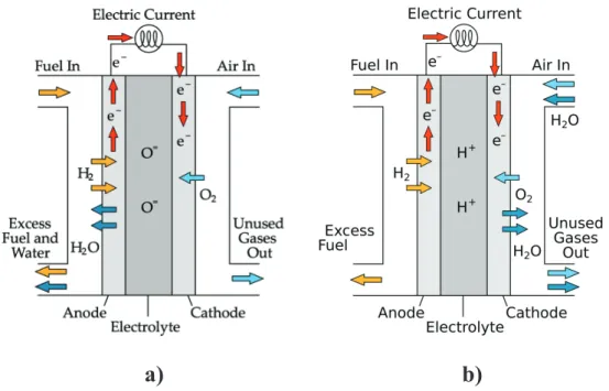
In a hydrogen-fuelled SOFC device, the overall redox reaction
2 + → 2
takes place in the three basic FC compartments (Figure 1.1): x Anode: the electrode where fuel oxidation takes place
2 → 4 + 4
x Cathode: the electrode where O2 reduction takes place
+ 4 → 2
x Electrolyte: the ceramic membrane that is a pure ionic conductor that drives ions in between the two electrodes and hinders electronic conduction.
Electrons flow through an external conductor that closes the circuit and conveys electricity out from the cell.
Depending on the type of electrolyte, Solid-Oxide Fuel Cells can be classified as:
x Anion-conducting devices (AC-SOFC), where O2- ions flow through the electrolyte
membrane. In this kind of devices O2 is reduced at the cathode, while water and other
x Proton-conducting devices (PC-SOFC), conveying H+ ions flow through the
electrolyte membrane. In this fuel cell protons produced at the anode side are carried out through the electrolyte and driven to the cathode, where the reduction semireaction takes place and water and other by-products are released. (Figure 1.1.b)
Figure 1.1 Working scheme of a) anion conducting Solid Oxide Fuel Cell (AC-SOFC) and b)
proton conducting Solid Oxide Fuel Cell (PC-SOFC).
SOFC materials
Electrolytes. The electrolyte is a membrane that must carry O2- in the case of AC-SOFCs and H+ in the case of PC-SOFCs. The main requirements of this component are:
x High ionic conductivity (ionic transference number close to unity); x Negligible electronic conductivity, to ensure high conversion efficiency; x High density, to ensure no gas diffusion;
x Chemical stability (it must be stable at operating temperature both to reducing and oxidizing atmospheres);
x TEC comparable to anode and cathode electrodes.9
Oxide-ion conducting electrolyte materials are typically: x Fluorite-like materials;
x Perovskite-like materials;
5
x La2Mo2O9 (LAMOX)
x Apatite and melilite structures.12
Figure 1.2 Arrehenius plot for different electrolytes.128
Fluorite-like Yttria-stabilized ZrO2 (YSZ) is the current commercially available oxygen-ion
conductor for SOFC applications, due to its long-term stability under operating conditions. If compared with other electrolytes (See Figure 1.2) YSZ has not a very high ionic conductivity (~10-2 S/cm at 800-1000°C) and the need to use high operating temperatures makes this material not suitable for IT-SOFC and LT-SOFC devices, especially for small scale applications.11,12 ScSZ (Sc-doped ZrO2) was also tested as electrolyte and showed superior
oxygen-ion conductivity, but the expensive cost of Sc makes unfeasible the use of this material.12–14
Among AO2 fluorite-like materials, valid alternatives have been searched for, in order to
replace YSZ in SOFC large-scale production and develop devices working at lower temperatures. Gd-doped and Sm-doped CeO2 (GDC and SDC) showed much higher
oxygen-ion conductivity than YSZ in the range between 500-700°C.12,15 It must be taken under consideration that at low pO2 and above 600°C these materials have a non-negligible amount
of electronic n-type conductivity, due to the presence of the Ce4+/Ce3+ redox couple, that must be controlled in order to avoid ohmic losses in the cell.16
Another fluorite-like oxygen-ion conductor is δ-Bi2O3: among the AC-SOFC electrolytes this
material shows the highest ionic conductivity in its pure form (~1 S/cm at 750°C).17 Two main problems are related to the use of this electrolyte: i) due to the polymophism of pure Bi2O3, the oxygen-ion conducting δ phase exists only in the narrow range between
730-824°C; ii) the Bi2O3 oxide is unstable under reducing atmospheres, where bismuth is reduced
to Bi0. To solve the former problem various dopants, isovalent or aliovalent to Bi3+, can be added, while the use of Bi2O3 in combination with more stable materials (e.g. doped CeO2) on
the fuel side has been proposed to tackle with the latter issue.17–25 Among ABO3
perovskite-like materials, lanthanum gallate doped with Sr on the A site and Mg on the B site exhibits high ionic-conductivity.12,26–29 Current issues for LaGaO3 are related to the formation of
secondary phases depending on dopant concentration.30,31 On the other hand, it was also found that addition of very small amounts of Co or Fe on the B site, enhances ionic conductivity.32,33 New electrolytes include La2Mo2O9 (the so-called LAMOX). Again, this
material has some issues related to the stabilization of the conducting polymorph (cubic β-phase), that can be achieved by doping the La site with alkaline or alkaline-earth cations, and the Mo site with less reducible cations (as W).12,34–36 Another class of new materials is constituted by Bi4V2O11-related structures (BIMEVOX), belonging to the Aurivillius series.
These structures are made up by alternating layers of Bi2O22+ and perovskite VO3.52-. Also in
this case room temperature stabilization of the conducting γ phase can be achieved by doping with Cu, Ni, Co.12,37–40 Apatite and melilite structures, based on tetrahedral moieties XO4,
were considered as novel electrolyte for SOFC applications. Si- and Ge-based lanthanum apatites, with La9.33+x(XO4)6O2+3x/2 (X=Si, Ge) composition, show an ionic conductivity based
on the presence of interstitial oxide-ions that can be driven through the bulk material.12,41,42 Other electrolytes such as La1-xBa1+xGaO4-x/2 exhibit both oxide and proton conductivity. In
this case oxygen-ions diffuse through the tetrahedral moieties of gallium.12,43 Finally, also LaSrGa3O7, with a melilite structure, made up by layers of corner-sharing GaO4 moieties that
form pentagonal rings, has been taken under consideration because of its interstitial oxide-ion conductivity.12,44,45
In Section 2, doped lanthanum gallate and bismuth oxide electrolytes for IT-SOFC applications will be analyzed in detail.
Anodes. Anode SOFC materials must fulfill the following requirements: x high catalytic activity towards the fuel oxidation semireaction;
7
x good ionic and electronic conductivity; x stability under reducing atmosphere;
x high surface area to ensure the fuel diffusion of gases towards the electrolyte; x good compatibility with the electrolyte.
Anode materials can be of two types:
x Ni/electrolyte cermets, that are porous composites constituted of Ni dispersed in the electrolyte material phase;
x Single phase, Mixed Ionic-Electronic Conductors (MIECs).
The use of Ni/electrolyte cermets46 simultaneously ensures a very high catalytic activity towards fuel oxidation and avoids detrimental micro-structural effects typical of the use of the pure metal as electrode, such as coarsening of Ni grains and high thermal expansion coefficients. In the past years, other transition metals (ex. Fe, Pt and Au) were also tested for the use as anode materials, but Ni remains undefeated in terms of catalytic activity, playing the double role of catalyzing the H2 oxidation and conducting electrons.9,47–49
The most used SOFC composite anode material is then Ni-YSZ cermet, that works at temperatures t 800°C. The catalytic activity of this cermet is characterized by the so-called hydrogen spillover mechanism reported in Figure 1.3, where the Three-Phase Boundary (TPB) between Ni, YSZ and H2 is represented. TPB is the active catalytic region where fuel
oxidation takes place: at the TPB H2 interacts with Ni0 particles, which have the double role
of catalyzing fuel oxidation and driving electrons to the external circuit. On the other side, the YSZ cermet component ensures the transport of the O2- anions, that react with H+ to release water as by-product.
As outlined above, fuel supply is one of the most important issues related to the cost of SOFC technology, and the most affordable choice for the commercialization is the use, instead of pure hydrogen, of widely available hydrocarbon fuels. In this context, research is oriented towards fuelling with methane and short-chain hydrocarbons from natural gas, due to their larger availability. These fuels can be reformed inside the FC plant: the possible approaches use the heat produced by the FC operation for i) indirect reforming by an accessory reformer placed in close thermal contact with the FC compartment, or ii) direct internal fuel reforming. In the latter operation scheme, the reforming reaction is directly carried out at the anode compartment, with advantages in terms of heath transfer and exploitation of the steam produced at the anode. When methane feeds the SOFC, together with the oxidation reactions
CH4+4O2-Æ CO2 +2 H2O +8e
-CH4+O2-Æ CO + 2H2+2e
also the following detrimental reaction takes place
CH4 ↔ C + 2H2
leading to carbon deposition that causes poisoning of the electrode.51,52 Moreover, H2S
present in natural gas can lead to sulphur deposition, which is also detrimental for the anode catalytic activity. These sources of rapid poisoning with carbon involve of course hindering of direct oxidation of CH4 at Ni-containing anodes.47,53
Alternative anodes to Ni-YSZ, with lower activity towards hydrocarbon cracking reaction have been proposed during past years. A composite anode consisting of Cu and 20 % Sm-doped CeO2(Cu-SDC) was proposed, due to the good electronic conductivity of Cu and
simultaneously due to the low catalytic activity towards the C-H cracking54,55 Cu alloys with Ni supported on silica or ceria were found to reduce the activity towards cracking: in particular, Ni/Cu-GDC was proved to have very good catalytic and redox properties towards CH4 oxidation and decomposition.56 Ni-Ce-ZrO2 and Ni-Ce,Y-ZrO257 were also proved to be
valid cermet materials.
Talking about the goal of lowering SOFC operating temperatures, other Ni-ScSZ,58 Ni-gadolinia-doped ceria (Ni-GDC), Ni - samarium-doped ceria (Ni-SDC)59–62 and Ni-LSGM63 anodes have been proposed as alternatives to Ni-YSZ cermet.10
9
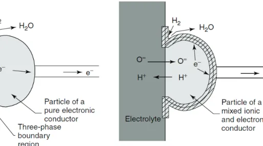
Figura 1.4 Comparison between a TPB zone in a cermet and a TPB zone in a mixed
electronic/ionic conductor (anode or cathode component)53
MIECs single-phase anodes were proposed as valid alternative to cermets. Anodes based on perovskite and fluorite-type materials have been proposed as suitable candidates that can promote direct oxidation of CH4, limiting detrimental poisoning effects. Moreover, MIEC
materials show an extended TPB if compared with cermets (Figure 1.4). Among MIECs, ABO3 perovskites were widely investigated: in these compounds the A site is doped with a
bivalent cation (usually Sr) in order to introduce oxygen vacancies, while the B site is modified by insertion of a transition metal (Mn, Fe, Co, Ni) in order to obtain a redox centre. For instance, it was demonstrated that La1-xSrxCr1-yMyO3 (M = Mn, Fe, Co, Ni) improves the
catalytic properties for methane reforming.47,64 While Ni doping on the B site seems to have the higher catalytic activity, it can undergo to Ni exsolution under reducing atmospheres. La 1-xSrxCr1-yFeyO3 shows a better catalytic activity than the most used La1-xSrxCr1-yMnyO365 and
compositions such as LSCrF1030 were found to be able to catalyze the oxidation of H2S to
SO2 and to overcome sulphur deposition starting from 600°C.66
Doped fluorite-like CeO2 was also investigated as MIEC. Under the reducing anodic
environment, cerium oxidation state is lowered from +4 to +3 and some oxygen vacancies are created. As in the case of perovskite anodes, doping ceria with transition metal introduces redox centres in the material. Examples of transition metal doped ceria used for anode applications are Mn- and Y-doped CeO2;67 Mo- and rare earth metal-doped CeO2 is also
Cathodes. The requirements for cathode SOFC materials are:9
x Catalytic activity towards O2 reduction;
x High electronic conductivity;
x High surface area to ensure O2 a high concentration of available reduction centres;
x Thermal expansion comparable with the other FC components; x Chemical stability towards operating conditions;
x Low solid state reactivity towards electrolyte membrane;
The oxygen reduction semireaction is accomplished through a mechanism involving several steps: i) dissociative O2 adsorption at the cathodic surface; ii) electronic charge transfer; iii)
O2- surface and bulk diffusion; iv) O2- transport to the electrode/electrolyte interface.10 Due to the high activation energy of O2 reduction reaction, lowering the temperatures entails that the
cathode compartment is the major source of electrical losses.
The p-type semiconductor La1-xSrxMnO3-δ (LSM) shows the electrode requirements
previously listed for cathodes. However, LSM has a TPB zone limited to the region where O2,
cathode an electrolyte are in contact (Figure 1.4); for this reason the LSM morphology and the formation of secondary phases at electrode/electrolyte interface can dramatically influence the catalytic activity of this cathodic material.69
Therefore, the preferred materials for cathode applications are MIECs perovkites, where TPB is extended to a 3D dimensionality. In these materials the O2 surface exchange and
bulk/surface diffusion are the rate determining steps of the O2 reduction semireaction. The
advantages in using MIECs are most evident for SOFCs operating at low temperatures (~650°C), because at lower operating temperatures the polarization of the cathode tends to increase.53
Among MIECs, three main classes can be identified:
x Simple ABO3 perovskites (LaCoO3, BaCoO3, LaFeO3);
x Ruddlesden-Popper perovskites An+1BnO3n+1 (Ln2(Ni,Co, Fe, Cu)O4+d where Ln=Nd,
La or Pr);
x Double perovskites AA´B2O6 (RBaCo2O5+d where R=rare earth, 0≤x≤1).69
Among simple cubic perovskites, (La, Sr)(Co, Fe)O3 (LSCF) has been extensively studied as
11
Fe doping has the opposite effect.10,69,71 Another promising cathode for LT-SOFC and IT-SOFC applications is Ba0.5Sr0.5Co0.8Fe0.2O3, that exhibits fast bulk and surface diffusion at
600°C.69 Further cathodic materials can be found in the class of Ruddlesden-Popper perovskites. These oxides have composition An+1BnO3n+1 and are made of n ABO3 layers
interposed in between AO rock-salt layers;69,72 the A cations are usually alkaline or rare earth metals, while B species are transition metals. Examples of compounds with n=1 are La2NiO4+δ and La2CuO4+δ, characterized by the presence of excess oxygen, that is interstitially
hosted between two perovskite layers. It was proved that this oxygen in excess leads to a faster ion diffusion compared to defective cuprates, due to the anisotropic nature of oxygen-ion transport73 through the ab plane of the rock-salt-like A2O2 layer.74,75 The advantage with
respect to the isotropic diffusion in simple perovkites is that the Ruddlesden-Popper materials have not to be heavily substituted to induce the formation of oxygen vacancies and so they are not subjected to defect interaction.
Finally, double perovskites AA´B2O6 (A=rare earth, A’=alkaline metal and B=Co, Mn) have
been recently proposed as IT-SOFC and LT-SOFC cathodes. These materials have A and A’ alternating layers, with oxygen vacancies mainly set on the A planes, so forming channels that enhance ionic conductivity.69,76
2. ELECTROLYTES FOR AC-SOFC
2.1. Fluorite and perovskite-type electrolytes
Conventional oxide-ion conducting electrolytes for AC-SOFC applications have the following types of structure:
x Fluorite-like (AO2);
x Perovskite-like (ABO3).
Fluorite-like electrolytes show an AO2 structure, where A cations are arranged in an fcc
network and have a cubic coordination with O atoms. Each oxygen is in turn coordinated with four A cations, leading to tetrahedral moieties. (Figure 1.5 a)
On the other side, perovskite-like materials have an ABO3 structure, where the A cation has a
Figure 1.5 a) Fluorite-like AO2 structure (A-site cations and AO8 polihedra in blue and O
atoms in red). b) Ideal cubic perovskite-like ABO3 structure (A-site cations in green, B-site
cations and BO6 polyhedra in blue and O atoms in red).
The common features that make this kind of structures highly efficient oxygen-ion conductors are:
x High concentration of oxygen vacancies (VO): in order to allow anion diffusion
inside the electrolyte sublattice, VO defects must be introduced. Oxygen vacancies are
commonly introduced by doping with cations having lower charge than the regular site cation. By the way, some solid electrolytes could have an intrinsically defective oxygen-ion sublattice in their undoped pure form.
x Energy equivalence of the conductive sites: the activation barrier of O2- diffusion
inside the structure is strongly influenced by the energetic equivalence of oxygen sites. Indeed, diffusion is favoured if O2- diffusion paths are evenly distributed and then equally probable within the oxide matrix. Oxygen-ion diffusion can be typically hindered by a pronounced size mismatch between regular cation and dopant, that can lead to marked local distortions (for instance, BO6 octahedra tilting and deformation in
perovskite-like structures), with consequent overall lowering of symmetry in the system.77
x Limited defect interactions and low activation energy barrier (less than 1 eV):78,79
the amount of dopant and vacancies introduced in the lattice must be taken under control. Indeed, defect interaction could strongly affect the electrolyte performances, severely damping O2- diffusion and enhancing the activation energy barrier that should
13
The scientific literature on fluorite and perovskite electrolytes is so huge that an attempt to give a comprehensive description of the advances in this field is helpless. Instead, the following Sections 2.2 and 2.3 are dedicated to an account of the state-of-the-art for two representative oxides of these two classes of ionic conductors, δ-Bi2O3 and doped
lanthanum gallate, respectively. These compounds are deeply investigated in this doctoral thesis due to their outstanding oxide ion conductivity and, consequently, to their interest as reference compounds to study the mechanism of oxide-ion solid state conduction.
2.2. δ-Bi
2O
3Among all solid electrolytes, δ-Bi2O3 exhibits the highest oxygen-ion conductivity known so
far (about 1 S∙cm-1 at 750°C, two orders of magnitude higher than the commercially used YSZ) (See Figure 1.2) and for this reason it is considered the reference compound in the field of solid state anionic conduction.17
The high-temperature phase of bismuth oxide, the so-called δ-Bi2O3, shows an average AO2
fluorite-like structure belonging to the Fm-3m space group. The incredibly high oxygen-ion conductivity of this phase is related to its intrinsically defective oxygen-ion sublattice, that exhibits a 25% of vacant oxygen sites in its unit cell, giving rise to a BiO1.5(VO)0.5
stoichiometry.17,80 Despite its stunning oxygen-ion conductivity, Bi2O3 shows two main
drawbacks concerning its concrete use as electrolyte in IT-SOFC technology:
x The δ phase of bismuth oxide is thermodynamically stable only between 730 and 825°C.
x Bismuth oxide is unstable under H2 atmosphere, where Bi3+ is reduced to Bi0.
The literature accounts first drawback can be easily solved by doping Bi3+ site with isovalent or aliovalent dopants, which stabilize the δ-phase at room temperature, significantly extending the range of accessible temperatures.
Moreover, the presence of a huge concentration of intrinsic vacancies implies that the material can be doped with cations of the same or even higher valence than Bi3+, so that VO
concentration can be strategically modulated in order to tailor the diffusion properties of the electrolyte.17–24 For what concerns Bi3+ instability under reducing atmospheres, the use of bismuth oxide in combination with more stable materials (i.e. doped CeO2, YSZ) on the fuel
a)
b)
Figura 1.6 a) Coordination polyhedra around Bi in ideal fluorite-like δ-Bi2O3 and b)
coordination polyhedra around O. (Bi atoms and BO8 polihedra in purple, O atoms and OBi4
polyhedra in red).
α, β, γ and δ-Bi
2O
3Depending on the temperature range, bismuth oxide can adopt four allotropic forms, named α, β, γ and δ-Bi2O3.17
At room temperature, bismuth oxide exists as the non-conductive monoclinic α-Bi2O3,
belonging to the P21/c space group, where alternating layers of bismuth and oxygen atoms are
arranged. Bi3+ coordination is comprised between five and six, leading to a distorted octahedral local environment and empty channels can be observed (Figure 1.6 a).81,82
At about 730°C α-Bi2O3 undergoes a phase transition to δ-Bi2O3, that exists up to 825°C, its
melting point temperature.
δ-Bi2O3 adopts an fcc network of four Bi3+ occupying the 4a sites of the Fm-3m space group
and having a defective cubic coordination: to ensure a neutral charge two oxygen vacancies per unit cell must be introduced. On the other side, oxygen-ion sublattice is composed by six atoms occupying the 8c sites and having a tetrahedral coordination with Bi atoms (Figure 1.6
a and b).80,83–85
By cooling down the δ-phase, two other metastable bismuth oxide polymorphs have been observed: β-Bi2O3 (Figure 1.7 b) at and γ-Bi2O3 (Figure 1.7 c).86–88
The tetragonal β-Bi2O3 belongs to the P-421c space group; it is obtained at 650 °C by cooling
the G-form and shows a pseudo-bypiramidal trigonal coordination around Bi3+. The γ-Bi 2O3
15
has body centred cubic I23 symmetry and is characterized by an octahedral coordination of Bi3+. It is obtained at 640 °C by slowly cooling down the δ-phase.
Figure 1.7 a) α-Bi2O3, b) β-Bi2O3 and c) γ-Bi2O3.
δ-Bi
2O
3: oxygen-ion sublattice models for vacancy arrangement
Several models have been proposed to describe the oxygen vacancies arrangement in pure δ-Bi2O3.
Sillen et al. suggested a <111> ordered defect sublattice model, that was rejected by Gattow et al. who proposed a model where each of the oxygen 8c sites has equal probability (75% of the sites) to be occupied.80,82
Willis et al. studied by Neutron Diffraction fluorite-type materials like CaF2, UO2 e ThO2.89
They demonstrated that the structure of the anionic sublattice of these oxides can be interpreted by a displacement of oxygen-ions from their regular tetrahedral 8c site (¼, ¼, ¼), towards one of the four <111> directions, giving rise to 32f displaced sites (¼+δ, ¼+δ, ¼+δ).
c)
b)
a)
The same model could be extended to the δ phase of bismuth oxide where the incredibly high ionic conductivity can be attributed to the presence of an increased number of conductive sites. Indeed, Battle et al. demonstrated through Neutron Diffraction that oxygen-ions in δ-Bi2O3 have the same probability to occupy both 8c and 32f sites.83,84
By a pioneering X-Ray Absorption Spectroscopy experiment at high temperatures on undoped δ-Bi2O3, Koto et al. confirmed the displacement of oxygen-ions from their
tetrahedral sites of the fcc cation network. They observed a distribution of two Bi-O distances in the first shell, in agreement with a random displacement of oxygen ions from their regular
8c sites.85
It was also observed that, due to the stereochemically active 6s2 lone pair on Bi3+, intrinsic
vacancies in fluorite-like bismuth oxide tend to orient themselves in preferential directions. In particular, pure δ-Bi2O3 tend to order vacancies in the <110> direction, that would ensure a
high degree of disorder in the system, while doping with rare earth cations, that possess a lower polarizability than Bi3+, induces a preferred vacancy allignement in the <111> direction.83,84
Dopant effect on δ-Bi
2O
3stabilization
As it has been previously explained, the stabilization of an average fluorite-type δ-phase to room temperature can be achieved by doping bismuth oxide with cations isovalent o aliovalent to Bi3+. However, even if doping bismuth oxide with various heteroatoms extends the stability of the cubic phase to lower temperatures, this usually happens at the expense of conductivity that is generally decreased if compared to pure δ-Bi2O3.
From a structural viewpoint, bismuth oxide is an extremely complex system and a great variety of possible phases can be achieved through a delicate balance between dopant concentration, temperature treatment and heating rate. Some isovalent and higher valence dopants were found to be very effective in both stabilizing the δ phase and maintaining a good ionic conductivity in the material.17 For example, the insertion of trivalent cations on the Bi3+ site can lead both to the stabilization of an fcc network, typical of the fluorite-like phase, or of a rhombohedral phase, depending on the size of the M3+ cation and on the dopant concentration.17 It was observed that dopants with a relatively large radius stabilize the rhombohedral phase, while dopants with relatively small radius tend to stabilize the cubic phase. In particular (Bi2O3)1-x(M2O3)x solid solutions, where M=Y, Er, Dy, Gd generally lead
17
rhombohedral phase. Among these highly conductive solid solutions, Bi2O3-Er2O3 system
was proved to have one of the highest ionic conductivity among doped systems (about 0.4 S∙cm-1 at 700°C in air for 20%mol of M2O3 doping).17,90–92
The minimum concentration value (xmin) required to stabilize the cubic phase in (Bi2O3) 1-x(M2O3)x can be correlated with the dopant ionic radius, showing two opposite trends:
x the ionic conductivity increases with the ionic radius; x xmin value increases with the ionic radius.
It was also observed that doped bismuth oxide electrolytes with high values of xmin cause a
low ionic conductivity in the material.17,91,92
Due to the presence of a 25% of intrinsic vacancies in pure δ-Bi2O3, it is possible to dope the
material with higher valence cations without severely affecting the overall oxygen vacancy concentration. In this context, doping of bismuth oxide with cations such as Re7+ or Mo6+, V5+, Nb5+, and Ta5+ represents a continuing topic of research;19,20 in particular, much interest has been devoted to the insertion of pentavalent Ta5+, Nb5+, and V5+ cations.21–24,93
The role of such small and high-valence cations is thought to be two-fold: x stabilizing the fluorite structure at low temperature;
x providing a favourable pathway for the anion conduction.
(Bi2O3)1-x(M2O5)x solid solutions (with M=V, Nb, Ta) show a great variety of
superstructures, that have been characterized through diffraction techniques (ED, ND, XRD).93 Indeed, from the viewpoint of structural analysis, not only the dopant ionic radius and concentration have a role, but also the charge unbalance introduced by M5+ cation must be carefully considered. M5+ cations in the matrix of Bi2O3 show the tendency to gather in
highly symmetric structural motives, giving rise to complex superstructures. The orientation of these motives and their interaction with the oxide matrix has two competitive driving forces:
x the charge balance (which depends on the amount of dopant introduced); x the coordination of the dopant (which depends on the type of M cation).
For example, in (Bi2O3)1-x(V2O5)x solid solutions vanadium is organized in VO4 moieties that,
superstructure) or further aggregated with other VO4 tetrahedra (Type II), where V cations are
generally clustered in groups of four atoms.94,95
Vanadium-doped bismuth oxide is very conductive due to the possibility of a large local structure rearrangement around V5+, that assists the anion diffusion through the flexible first shell V5+-O coordination.21
Among higher valence dopants, Ta and Nb show very similar behaviour in the structural stabilization of δ-Bi2O3, because they possess identical ionic radii. Nevertheless, Ta doping
was generally less studied than Nb doping.93,96
Diffraction studies93,96 showed that (Bi2O3)1-x(Nb2O5)x and (Bi2O3)1-x(Ta2O5)x solid solutions
respectively adopt NbO6 and TaO6 rigidly coordinated octahedral environments. Depending
on dopant concentration, these NbO6 and TaO6 octahedra could be isolated (Type I
superstructure) or could further aggregate giving rise to pyrochlore-like A2B2O7 structures
(Type II). Among these compositions, the highest anionic conductivity (0.19 S∙cm-1) was observed for the system (Bi2O3)1-0.85(Nb2O5)0.15.17,97
Ta-doped Bi
2O
3Diffraction studies demonstrated that Bi2O3−Ta2O5 solid solutions adopt different types of
superstructures, depending on the dopant concentration. Type I Bi2O3−Ta2O5 superstructures
are obtained below 10% of Ta and show isolated TaO6 octahedra. Between 10 and 25% of Ta,
TaO6 structural motives related to the pyrochlore structure appear and give rise to the
so-called Type II superstructure.96,98
In the A2B2O7 pyrochlore structure A and B cations are arranged in a fcc sublattice like in the
fluorite network, while the O2− anions form AO8 and BO6 coordination polyhedra. In this kind
of compounds, three different structural motives involving the B species can be discerned (Figure 1.8):
x strings of BO6 octahedra oriented towards the <110> directions;
x tetrahedral B4O18 clusters, arising from the interconnection of two BO6 strings;
x B7O30 clusters formed by two corner-sharing B4O18 tetrahedral clusters.
Because Bi2O3−Ta2O5 solid solutions have an A:B ratio that is larger than 1 (with A = Bi, B =
Ta), they show less interconnection between the octahedra with respect to the ideal pyrochlore structure, giving rise to “inflated pyrochlore” structures.93 To properly account for the long-range order in M5+-doped bismuth oxides, as required by the structural models based on
19
diffraction data, it was necessary to allow for a 3D incommensurate superlattice ordering.22,99,100
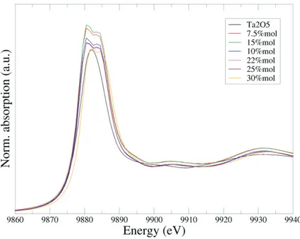
Although long range superstructures were characterized extensively in recent years by using a variety of structural techniques, such as synchrotron X-Ray Diffraction (SR-XRD), Electron Diffraction (ED),96 High Resolution TEM98 and Neutron Powder Diffraction (NPD),22 there is a lack of studies about the local environment of cations in Ta-doped bismuth oxide, while a deeper knowledge of the local structure around the dopant site would help to shed light on the role of the dopant in the stabilization of the δ-phase at room temperature and on the structural features that govern oxygen-ion conduction inside this material.
a)
b)c)
d)
Figure 1.8 a) Pyrochlore-like A2B2O7 b) isolated BO6 octahedra, c) tetrahedral B4O18 clusters
2.3. LaGaO
3Doped LaGaO3 (LG) represents one of the top performing oxygen-ion conducting electrolytes
known so far.12,101–104
This material is a perovskite-type oxide with ABO3 structure belonging to the orthorhombic
Pbnm (Figure 1.9) space group. The A cations have a 12-fold coordination with oxygen and
an approximately cubic coordination with BO6 octahedra. Due to the high structural flexibility
typical of perovskite materials, doping with small percentages of Sr2+andMg2+ on the A and B sites, respectively, allows LG to accommodate a large concentration of anion vacancies, according to the following equations:
2LaLax + 2SrO + Oox Æ 2SrLa’ + VO∙∙ + La2O3
2GaGax + 2MgO + Oox Æ 2MgGa’ + VO∙∙ + Ga2O3
This doping with bivalent species allows reaching very high anionic conductivity, around 0.14 S/cm at typical IT-SOFC operating temperatures, for the compositions La0.9Sr0.1Ga0.9Mg0.1O2.85 (LSGM1010), La0.9Sr0.1Ga0.8Mg0.2O2.85 (LSGM1020) or
La0.8Sr0.2Ga0.8Mg0.2O2.8 (LSGM2020).26–29,104,105 Moreover, a thermal expansion coefficient
(TEC) of about 11.5x10⁻⁶ K-1, is compatible with the most common SOFC electrodes.
However, some drawbacks must be taken into account. For example, secondary phases due to the loss of Ga2O3 at sintering temperatures (around 1400°C) are usually formed during the
preparation of the ceramic electrolyte, even if the presence of these phases does not drastically affect the conduction properties of the material.30,31 Another problem related to the long term durability of the complete cell is that the mechanical and bending strength of this electrolyte at operating temperatures is not very good.104
21
Dopant and co-dopant effect on the ionic conductivity
As previously described, doping La3+ and Ga3+ with alkaline earth elements, such as Sr2+ on the A-site and Mg2+ on the B-site, leads to a high anionic conductivity of LG materials (See
Figure 1.2), due to the incorporation of VO defects that are absent in the pure compound. In this way, La1-xSrxGa1-yMgyO3-δ phases are formed, and the best conductivity values, that are
definitely higher than YSZ at 800 °C, are found for x=0.10-0.20 %mol and y=0.15-0.20%mol.26–29,104
The effect of other alkaline earth metals has been tested both on the A and B site, but Sr2+ and Mg2+ (1.44 Å and 0.72 Å) have similar size compared to La3+ and Ga3+(1.36 Å and 0.62 Å), leading to the lowest size mismatch (and to the less amount of distortion) between dopant and regular site cations. Indeed, Ishihara et al. and Stevenson et al. tested Ca2+, Sr2+and Ba2+ doping on the A-site and demonstrated that ionic conductivity is higher in the case of Sr2+.27,33 It was further explained through Pair Distribution Function (PDF) analysis and Density Functional Theory (DFT) simulations, that the decrease in ionic conductivity in Ba-doped lanthanum gallate (La0.95Ba0.05Ga0.8Mg0.2O3-δ) can be ascribed to a defect interaction between
Ba2+ and VO that limits oxygen-vacancy mobility.106 On the other side, if Ba2+ is used as
co-dopant together with Sr2+ on the La3+ site (La0.8Sr0.2-xBaxGa0.8Mg0.2O2.8), an increase of
conductivity of 44% with respect to LSGM was observed (i.e. La0.8Sr0.15Ba0.05Ga0.8Mg0.2O2.8
has 0.047 S∙cm-1 at 800°C).107
From a computational viewpoint, Khan et al. tried the entire alkaline and alkaline-earth metal series, on the A and B-sites and demonstrated that Sr2+ and Mg2+ have respectively the lower solution energy (Figure 1.10).108
Figure 1.10 Trend of the solution energy as function of the ionic radius of alkaline and
Co-doping of the La3+ A-site with small amounts of rare-earth cations such as (Pr, Nd, Sm, Gd, Y, Yb) has also been tried and compositions like (La0.9Nd0.1)0.8Sr0.2Ga0.8Mg0.2O3-δ and
La0.45Pr0.4Sr0.2Ga0.8Mg0.2O2.85 seem to have a lesser effect on the electronic conductivity than
other rare earth dopants, while maintaining a good ionic conductivity.104,109
For what concerns the B-site, Mg2+ was proved to be the most effective dopant to enhance ionic conductivity.104 While co-doping with Ni, Mn and Cr increases electronic conductivity, adding small amounts (about 5-10%mol) of Co or Fe minimize the ohmic resistance of the electrolyte and the overpotential of anodes and cathodes, maintaining an oxide-ion conductivity similar to the parent LSGM composition.32
Structural effect of A-site and B-site substitution
Pure LG has an orthorhombic Pbnm unit cell (see Figure 1.9) until 160°C, where it undergoes a phase transition to the R-3c rhombohedral phase, which is maintained up to 800°C. Although the two phases have the same local structure, they differ in the respective long-range arlong-rangements.
Neutron Diffraction studies have demonstrated that doping with Sr2+ and Mg2+ on the A and B sites, respectively, induces a reduction of tilting that is intrinsically present in undoped LG, and increases the symmetry of the octahedral sites.110
Due to the structural flexibility of this material, the amount of dopant introduced on A and B sites can also have an influence on the long-range structure: for example, at the limit of no Sr substitution, LaGa1-xMgxO3-x/2 (LGM) phases are obtained. Introducing 10%mol of Mg on the
B site110 leads to the orthorhombic Ibmm space group, while 20%mol does not modify the symmetry of the lattice and the original Pbnm space group is maintained, with only an expansion of the cell parameters with respect to pure LG. At this composition, the Goldschmidt tolerance factor approaches the value of 1 and GaO6 octahedra are close to the
regular ones, with a slight lengthening of the Ga-O bond distances and a decrease of the tilting angle between adjacent Ga polyhedra. Some studies also report that, when 20% of Sr is introduced on the A site, a La1-ySryGa1-xMgxO3-(x+y/2) phase with tolerance factor equal to 1
and a cubic Pn-3m symmetry is obtained. In this case, GaO6 octahedra show a shorter Ga-O
average distance and the distortion in the perovskite is considerably lowered or even cancelled out.111 For co-doping with cobalt on the B-site, Stevenson et al. reported the presence of a cubic, orthorhombic or rhombohedral phases.33
23
It is well acknowledged that the remarkable structural flexibility of doped LG certainly plays a determining role in the anion conduction mechanism inside the electrolyte, so that an intense research activity has been devoted to correlate dopant-vacancy interaction phenomena with oxygen-ion diffusion, both computationally and experimentally. Several studies exist about long-range characterization of lanthanum gallate through X-Ray Diffraction (XRD), but to the best of our knowledge there are no studies that can be found about the short-range characterization through X-Ray Absorption Spectroscopy (XAS). A detailed short-range characterization would allow completing the information about the local structure of doped LG that, together with an ab initio computational analysis of both dopant preferential configuration and dopant-vacancy interaction would shed light on the oxide-ion diffusion mechanism.
Vacancy interaction with B-site cations
LG B-site analysis is pivotal for the determination of the oxygen-ion diffusion mechanism. A better understanding of the interplay between B-site occupation and oxygen vacancy position, correlated with both the energetics of the system and the local structure distortions, would be extremely useful to shed light on the structural features that favour or hinder oxygen-ion transport.
From a modelling point of view, atomistic techniqueshave been extensively used to probe dopant vacancy interaction in lanthanum gallate electrolyte.108,112,113
Khan et al.108 computed binding energies (Ebinding) for vacancy interaction with the A-site and
B-site cations in an orthorhombic phase and found that oxygen vacancies tend to be “trapped” by Mg2+ defects with Ebinding (Mg’GaV0∙∙)= -1.77 eV, while there is less interaction with the
Sr2+ defects, with Ebinding (Sr’LaV0∙∙)=-0.37 eV. This result is in agreement with the increase of
activation energy and decrease of ionic conductivity at higher Mg2+ concentrations experimentally found for La0.8Sr0.2Ga1-yMgyO3-δ, but disagrees with recent solid state NMR
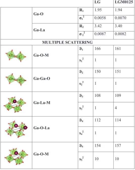
experimental findings and theoretical studies on doped lanthanum gallate.114,115 In particular, a recent theoretical investigation, based on a DFT approach combined with experimental NMR measurements on 71Ga, 25Mg and 17O nuclei for pure and doped lanthanum gallate, has demonstrated that oxygen vacancies are mainly set on Ga sites, while Mg coordination is found to be mainly octahedral. Moreover, chemical shifts on 17O nuclei, which are found to be sensitive to distinguish equatorial (Oeq) and axial (Oaxial) oxygen atoms in GaO5Vo local
environments, revealed a heavily distorted square pyramidal geometry, with a shortening of 0.08-0.09 Å of the Ga-Oaxial bond length. In addition, various configurations of the vacancy
with respect to Ga and Mg B sites in LaGa1-xMgxO3-x/2 were already investigated by DFT
calculations, considering three different Mg concentrations. In all cases, the Ga-Vo-Ga configurations were found to be the most stable ones. Nevertheless, for the x=0.250 concentration, the energetic range of the configurations was 16 kcal∙mol-1, while it was only half this value for the x=0.050 and 0.125 cases, with a modest energy difference between the Ga-Vo-Ga, the Mg-Vo-Ga and the Mg-Vo-Mg configurations, suggesting only a slight energetic preference for the Ga-Vo-Ga configuration. 113
Oxygen-ion diffusion mechanism
Another experimental NMR study confirmed that oxygen vacancies are mainly localized between two Ga atoms in bi-pyramidal coordination in the O1 apical position. The dynamics of the diffusion was modelled and two types of oxygen-ion motion were highlighted: i) slow diffusion-type random walk and ii) fast back and forth local jumps between two adjacent anion sites, that had different probability of Vo formation.115
Islam et al. investigated oxygen-ion diffusion through atomistic methods.108,112,113 The defect energy was computed along the diffusion path, allowing the lattice to relax at each position. A vacancy hopping mechanism along the edges of GaO6 octahedra was highlighted: oxygen-ion
migrates with a slightly curved trajectory in between two oxygen sites and this process would be promoted by the equivalence of the hopping sites of oxygen around B cation. The migration energy barrier of O2- = 0.73 eV is in good agreement with some experimental findings based on high temperature dc measurements (activation energy of 0.66 and 0.727 eV) and SIMS data (activation energy of 0.79 eV).113
In general, while atomistic and Molecular Dynamics (MD) methods have been largely used to probe doped lanthanum gallate,108,112,113,116 very few studies based on a DFT approach117,118 can be found and none of them reports an analysis of the oxygen-ion diffusion path. The anionic diffusion of electrolytes is mainly governed by i) the formation of oxygen vacancies and ii) the vacancy-mediated oxygen-ion migration. Sampling the potential energy surface of O2- diffusion paths in correspondence of the most stable configurations with an ab initio method would have the advantage to correlate the anion conduction mechanism with the electronic structure.
25
Cobalt co-doping on Mg B-site
It has been recently reported that co-doping the B site with Mg2+ and very small amounts of Co, minimize the ohmic resistance of the electrolyte and the overpotential of anodes and cathodes, maintaining an oxide-ion conductivity similar to the parent LSGM composition in the temperature range between 500°C and 900°C: compositions like La0.8Sr0.2Ga0.8Mg 0.2-xCoxO3±δ with x=0.05 and 0.10 (LSGMC2005, LSGMC2010) show an O2- conductivity of 0.2
S/cm at 700°C.32 Cobalt adopts different valence states (+2, +3, +4), depending on the temperature and oxygen partial pressure: this probably influences the local environment of Co site and consequently the conduction mechanism in LSGMC materials at SOFC operating conditions, involving simultaneous oxidizing and reducing environments on the two FC sides. Moreover, depending on the oxidation state and local environment, cobalt can show three different spin configurations:
x Low Spin (LS)
x Intermediate Spin (IS)
x High Spin (HS)
Considering the crystal field for an octahedral local environment typical of perovskite B-site, Co2+ always adopts the HS configuration (t2g5eg2), while Co4+ always adopts a LS
configuration (t2g5eg0). In the case of Co3+, the crystal field become very sensitive to the cobalt
surrounding species and for this reason it can assume LS (t2g6eg0), IS (t2g5eg1) and HS (t2g4eg2)
configurations.119
It is known from TGA data that LSGMC materials show a reversible O2 weight loss in air at
high temperature, which is thought to be compensated by a reduction of cobalt to Co2+ in two steps:33
From Co4+ to Co3+ OOx + 2 CoGa∙ ÆVO∙∙ + 2 CoGax +1/2O2
From Co3+ to Co2+ OOx + 2 CoGax ÆVO∙∙ + 2 CoGa’ +1/2O2
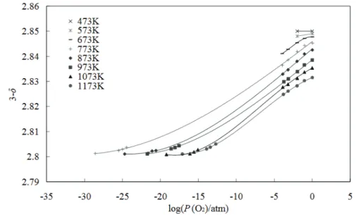
On the other side, a study on LSGMC2005 tries to correlate the variation of oxidation number of Co with PO2 and temperature variations. The study observes that, while in LSGM oxygen
nonstoichiometry does not depend on temperature and log(PO2),120 in LSGMC electrolytes
nonstoichiometry is strongly attributed to cobalt valence changes. In particular, oxygen vacancy concentration increases as logPO2 decreases and the temperature increases, reaching
a plateau at about 3-δ=2.80 (Figure 1.11) These data have been correlated with XANES measurements at both 5%H2-1.2% H2O-Ar at 573 K and 100% O2 atmospheres at 473 K,
revealing respectively Co2+ and Co4+ oxidation states in these conditions.120
Figure 1.11 oxygen partial pressure dependence of oxygen nonstoichiometry of LSGMC2005
at different temperatures.120
3. Cation interdiffusion at electrode-electrolyte interface
3.1. Electrode-electrolyte compatibility
Chemical/physical compatibility between electrode and electrolyte components has a large impact on the overall performances of SOFC devices in terms of working life and ionic conductivity throughout the device in both AC-SOFC and PC-SOFC systems. In order to ensure robustness and conductivity, electrode and electrolyte materials must exhibit two main requirements:121
x similar thermal expansion coefficients, to avoid mechanical stresses (es. crackings, delaminations, etc.) at operating temperatures;
x limited interdiffusion of chemical species at the interface.
Even if the materials have similar thermal expansion, cation interdiffusion has a very high impact on the long-term durability of the cell and must be minimized, because it can give rise to insulating contact phases at the interface between the two components at operating temperatures and atmospheres. Moreover, even the co-sintering process of cathode and anode
27
on the ceramic electrolyte can lead to the formation of a contact phase, that can seriously affect cell performances since the manufacturing process of the device.122–125
3.2. Synchrotron X-Ray Microscopy to probe compatibility
Studying interdiffusion phenomena at the electrode/electrolyte interface requires suitable techniques, whose choice is determined by the required resolution and by the type of needed information. In this context, compatibility issues have been traditionally investigated by means of electron microscopy (EM) techniques, such as Scanning Electron Microscopy (SEM), Transmission Electron Microscopy (TEM), High Resolution Transmission Electron Microscopy (HR-TEM) and Scanning Transmission Electron Microscopy (STEM).122–125 The main advantage in using an electron probe certainly lies in both the outstanding spatial resolution (from nm to Å) and in the huge amount of information that can be simultaneously obtained about the morphology, the structure and the elemental composition of the sample. The use of the techniques based on an electron beam probe allows to perform microchemical analysis on cross sections of the electrode/electrolyte assembly and to determine concentration profiles across the interface, in order to characterize the extent of cations interdiffusion between the two phases.122–125
Unfortunately, the use of EMs, has some serious drawbacks that can affect or limit the interface study. For example, electrons can cause aberrations, due to the electrostatic charging of the sample, that can affect the microscopy analysis. The attenuation length of the electron beam can be severely affected by the roughness of the surface during SEM analysis. TEM imaging requires a complex preparation of the sample, that must be extremely thin (about 100 nm), due to the strong scattering of the electrons. Moreover, studying interdiffusion phenomena at electrode/electrolyte interface requires a deep knowledge and control of the local structure around cations, that the EMs are not able to investigate. In some cases, contact phases or secondary phases have a composition that is only slightly different from the original structure (i.e. interdiffusion of cations inside a perovskite-type lattice), and working with diffraction tools is not enough to detect them.
In this context, even if the resolution is lower than EMs, X-Ray Microscopy (XRM) overcomes the drawbacks typical of EM (no electrostatic charging of sample, attenuation length of the beam large enough to ensure no influence by the surface roughness - about 1 to 5 μm - and higher thickness of samples - from 5 to 100 μm) and simultaneously allows to
characterize not only the morphology of the electrode/electrolyte interface, but also to obtain detailed local structure and chemical state information, which are essential for the design of SOFC with higher efficiency and long term durability.126
Various types of XRMs exist, working in different imaging modes: similarly to EMs techniques previously described, XRMs can work in full-field mode, as in Transmission X-Ray Microscopy (TXM), or scanning mode, as in Scanning X-X-Ray Microscopy (SXM). We have demonstrated in a recent study127 that SXM is an extremely suitable technique for investigating compatibility between SOFC materials. This technique allows acquiring X-Ray Fluorescence (XRF) elemental distribution maps based on fluorescence contrast by raster scanning the sample in two dimensions, using a sub-micrometric beam. Moreover, μ-XANES, μ-EXAFS and μ-XRF spectra can be recorded in selected points of the map by varying the energy around the absorption edge of the target element: in this way, information about elemental and chemical state can be achieved, together with quantitative mapping.
4. Objectives
The scientific literature concerning solid state electrolytes is extremely wide and the vast majority of the published papers are focused on the synthesis and functional characterization of these components.
The aim of this research is to investigate some of the structural features that have an influence on ionic conductivity in fuel cells.
The focus about electrolyte materials is on oxygen-ion diffusion in fluorite-like and perovskite-like structures. To this end, a detailed analysis of the short range structure of
the materials under investigation, combined with a computational approach, would allow to link the properties of these materials with the atomic structure and the electronic features. This would help to define criteria for the design of new materials with
improved properties.
In particular, two electrolytes for AC-SOFC applications, previously described in Section 2 of this chapter, have been studied:
x Fluorite-like δ-Bi2O3. With its average fluorite-like structure containing intrinsic vacancies in its undoped form, the high temperature δ-phase of bismuth oxide is considered the reference compound in solid-state anionic conduction, with the highest conductivity known so far (1 S∙cm-1 at 750°C).