doi: 10.17265/1934-7359/2017.07.004
Evaluation of Radon Indoor Pollution Risk in High
Efficiency Energy Buildings
Giovanni Zannoni1 and Jacopo Gaspari2
1. Department of Architecture, University of Ferrara, Ferrara 44121, Italy; 2. Department of Architecture, University of Bologna, Bologna 40126, Italy
Abstract: The target of achieving high energy efficiency standard in order to comply with the EU Directives is leading to remarkable
efforts to improve the performance of the building envelope. Excellent thermal insulation and airtight sealing of leakages are of the utmost importance to fulfil the expected targets. Unfortunately, airtightness produces the negative effect of increasing the indoor concentration of air pollutants like radon. Despite the seriousness of the problem is generally misconceived, long-term exposition to radon is acknowledged to be the second cause of lung cancer after smoke. The paper outlines the implications for the building sector and focuses on design and preventive criteria as well as on mitigation and remedial techniques.
Key words: Indoor quality, indoor pollution, radon, high efficiency energy buildings, design criteria.
1. Background and State of Art
1.1 Introduction and Context
Energy saving measures and energy efficiency design criteria, according to EU Directives (31/2010, 27/2012), are boosting the concept of a strongly insulated building envelope in order to avoid dispersion and air exchange between inside and outside. New high performing insulation layers, new waterproof membranes and vapour barriers as well as new high efficiency doubled glazed windows are all addressed to increase the thermal behaviour of the building envelope completely avoiding dispersions and recurring to mechanicals and equipments for air treatment.
No uncontrolled air exchanges between inside and outside are allowed in order to maintain optimal indoor comfort conditions and to obtain huge energy savings. On the one hand, this approach is the most viable solution to obtain significant results in reducing energy demand, but on the other hand, it strongly increases the risk of concentration of indoor domestic and natural
Corresponding author: Giovanni Zannoni, Ph.D., research
field: technology of architecture. E-mail: [email protected].
pollutants. Most of indoor pollutants are due to anthropic activities or to cleaning products as well as to furniture finishes or emissions from equipments and devices, while some of those agents come from natural sources.
Pollutants (CO2, NOx, VOC (volatile organic compound), etc.) normally produced during the daily activities carried out by the occupants or by HVAC (heating, ventilation and air conditioning) plants, can be easily diluted by natural or mechanical means of ventilation. However, this is generally avoided in low energy building, since avoiding the heat loss caused by ventilation a 50% saving of the total demand can be obtained, especially in winter. Avoiding dispersion through the building envelope, also the chance of removing the pollutant agents is strongly reduced. An adequate number of air changes is generally provided, on the basis of the internal air quality measured in the occupied spaces. Though such means of ventilation reduce the presence of “standard” pollutants, the depression they cause to the building can lead to natural pollutant inflow.
Even though it can be quite hard, the risks derived by anthropic origin can be reduced modifying the lifestyle
D
and habits of the households or of the final users of the building, while the risks derived by natural origin have to be adequately faced. The most relevant differences between these two families of pollutants concern the availability of information, the chance to identify and detect them in order to remove their source.
Among natural pollutants, radon represents one of the most dangerous agent currently known for a series of reasons: it is the second cause of lung cancer after smoke [1]; it is colourless, odourless, tasteless; it can be detected only recurring to specific and adequate devices; its presence has no relation with conventional anthropic activities.
1.2 Basic Information about Radon
Radon is an isotope—mass number 222 (222Rn)—belonging to the uranium radioactive group and derived by the uranium decay, the process through which a radioactive element changes into another substance emitting radiation. Like other natural isotopes with unstable configuration, it is called radionuclide and it can be easily found in rocks, soils and water [2]. Radon usually flows through the micro-cracks of the soil and is dispersed in the atmosphere. Unfortunately, when it is able to flow into a building, its concentration increases as well as the risks for health.
During the decay process, ionizing radiations are able to transfer a considerable amount of energy to the human body, damaging it at DNA (deoxyribonucleic acid) cellular scale and causing cancer pathologies. The IARC (International Agency for Research on Cancer) has included radon in Group 1 among definitely carcinogenic agents [3].
When inhaled, most of radon flows out through the breath or is eliminated by the tracheobronchial mucociliary epithelium system. Human exposure to natural ionizing radiation is an unavoidable condition of life on the Earth and radon is indicated to be responsible of the half of it. However, high concentrations and long exposures, increase the risk of
pathologies caused by the decay process. Therefore, “no risk” thresholds cannot be defined while acceptable risk thresholds can be estimated.
Avoiding dispersions of conventional buildings, recurring to high energy efficiency building envelope, means a proportional reduction of the chance to disperse radon and a significant increase of its concentration. So adequate design criteria have to be introduced in order to prevent radon inflow.
The environmental protection agencies of several EU member states are completely aware of the risks for the public health and began a number of surveys including geological monitoring in the last decades [4] as well as an intense dissemination action in order to disseminate information and data about the problem. Despite this, most of the risks are due to an underestimation of the problem in the building sector. The way the buildings are built and the features of materials and building components play a primary role in this issue. Radon becomes seriously harmful only when it is confined into a closed environment in which its concentration increases, so building design has to provide adequate concepts to prevent inflow and effective measures to disperse it in case of inflow. However, specific requirements concerning radon prevention are far to be conventionally adopted in current construction methods.
2. Radon and the Building Sector
2.1 Radon Inflow into Buildings
Radon is an inert gas able to migrate by molecular diffusion inside through the micro-cavities of the ground until it reaches the atmosphere through porosities and cracks. This leads to an atmosphere background value of about 10/15 Bq/m2. When radon reaches the foundations and/or the basement of a building, it is able to inflow by micro-cracks or porosities of the materials used for the ground floor and underground floor slabs and walls as well as through connection joints, or the points in which plumbing pipes, electrical and drainage cross the slabs. It has to
be said that, despite soil is clearly the radon main source, some building materials of natural origin can be radon-emitters, such as tuff, granite, and other rocks often used in traditional wall masonry.
Radon inflow is usually derived by physical phenomena such as convective air effects produced by the difference of pressure between lower and upper floors due to different thermal conditions (stack effect), or as a result of the pressure of the wind against the building (Venturi effect). A thermal difference of 10 °C between inside and outside associated to a wind speed of just 5 m/s produces a pressure of only 5 Pa which is able to trigger radon inflow from the soil. This phenomenon is usually stronger during the winter season when the heating system is operating and the thermal differences increase as well as during the night when doors and windows are usually closed.
Radon isotopes are able of limited own movements but are usually carried by dust particles, aerosols, VOC (volatile organic compound), water vapours, etc. till they reach human respiratory system where they deposit on the mucous membranes releasing energy—supposed to be the preceding phase of tumour biological damage—during the decay process.
A number of causes contribute to the radon inflow into the built environment. Of course, the geological and lithological features of the soil play a very relevant role and this is the reason why several National Environmental Protection Agencies across EU are engaged in monitoring activities for producing territorial risk maps. As radon is a soluble agent, the groundwater level is a relevant factor: water may infiltrate radon into cracks and porosities or move it across the soil level. Also, climate conditions can influence the phenomena as well as barometric pressure.
The most influencing factors are due to the technological features of the building:
construction system adopted for the basement or the ground floor level;
floor slab technology and typology;
presence of micro-cracks or porosities in the floor
slab;
lack of sealing around equipment pipes and ducts; flooring typology;
use of building materials with high porosity; open vertical connections between floors;
presence of chimneypot, kitchen hood, extractor fan, etc., which can increase the pressure difference between the building and the ground.
Some specific features of the building, such as the shape, the size, the arrangement of openings and rooms, orientation and exposure, etc., can also influence radon inflow as well as users’ lifestyle and habits.
2.2 Radon Detection and Measurement Units
Radon measurement is based on the number of particles emitted in the air by radon isotopes during the decay process. Radon is measured in Becquerels per cubic meter (Bq/m3) where one Becquerel stands for one decay per second.
European regulations set different limits for indoor environments concentration, varying from country to country and from existent buildings to new ones, in order to achieve the better relationship between risk of disease and the cost of remedies. The 90/143/Euratom recommendation sets a limit of 400 Bq/m3 in existing buildings and 200 Bq/m3 in the new ones [5], but values of several thousands of Becquerels can be found in many highly-polluted buildings [6].
However, there is no threshold concentration below which radon exposure presents no risk. Since guidelines of most countries consider acceptable values between 200 and 400 Bq/m3 [7], the recent WHO (World Health Organization) report [8] argues that even low concentrations of radon can increase the risk of lung cancer, suggesting values around 100 Bq/m3, that is a very low value for some EU regions.
The most recurring, reliable and cheap is the integration measurement method. It is carried out by placing a dosimeter in the living area in the lower floor of the building.
used in the countries included in WHO International Radon Project surveys [8]: ATDs (alpha-track detectors) and EICs (electret ion chambers). Both these devices do not require electrical power and provide a long-term integrated radon measurement. This is a very relevant feature as filed studies demonstrated that radon concentrations, measured in the same building, may vary daily, seasonally and yearly [9]. A reliable measure provides at least two consecutive periods of six months each, which are used to evaluate the average radon concentration in the building.
In order to assess the effectiveness of a remedial technique or to evaluate the chance of timing the suction systems, active EIDs (electronic integrating devices) or CRMs (continuous radon monitors) are required. Both of them need to be supported by electrical power but offer the ability to chart the concentration and fluctuations of radon gas during the measurement period giving the opportunity to assess variations in radon concentration while the system is off and on.
3. Design and Construction Criteria
An RU (research unit) based on the Department of Architecture of the University of Ferrara is involved in a joint research program in cooperation with the ISS (Italian National Health Agengy) and the ARPA (Environmental Protection Agency) of Lombardia and Veneto Regions with the aim to investigate design criteria and implication in preventing radon pollution in the built environment [10, 11].
The RU focused on developing effective design requirements to be introduced in new constructions and especially in those ones belonging to the high energy efficiency group and on defining adequate mitigation measures in order to reduce the radon risk in existing buildings. The methodological outlines and findings of the research activities have been tested in several case study applications either in the private or in the public sector.
However, relevant differences occur between new
construction and interventions on existing buildings. 3.1 Technological Solutions in New Constructions
Despite the concern which is usually related to a radioactive agent, very simple measures can be adopted in order to prevent radon inflow into a new building. Of course, this depends on the confidence of the design team with the problem and with the specific features of materials and technologies to be used.
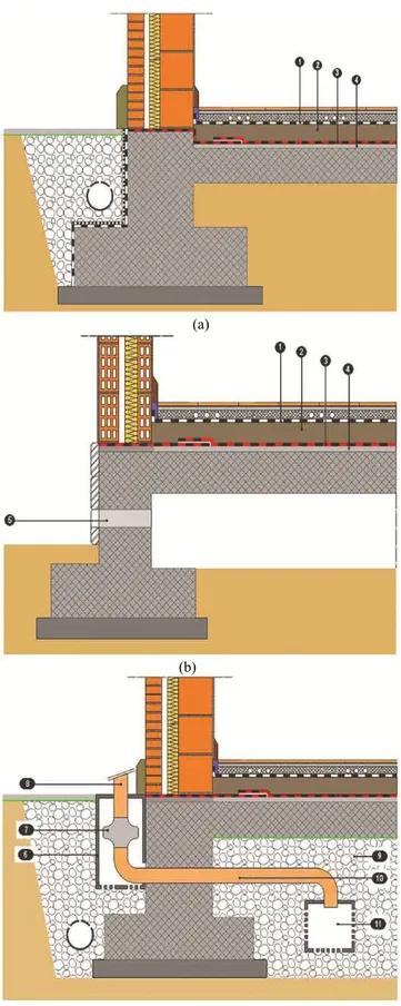
As the main radon source derives from natural emissions from the ground, it is easy to understand that the basement and/or the ground floor structures have to be adequately protected. As Figs. 1a, 1b and1c shows, a specific layer (see Point 3) is required in order to avoid the radon inflow.
This layer, which can be a simple waterproofing membrane, has to cover completely the surface of the floor slab in order to obtain a continuous element including under the walls. It has to be adequately sealed around the vertical structural elements as well as around the equipment pipes and ducts which cross the slab. Certificated, reliable and tough radon proof membranes are currently available on the market at a cost of about 6-8 €/m2, but a simple vapour barrier—if carefully placed—represents a safe obstacle to radon inflow. Guidelines from BRE (British Research Establishment) suggest the use of a simple thick polyethylene membrane [12].
As Fig. 1b shows, a crawl space under foundations or ground floor slab supports radon dispersion in the atmosphere: the ventilation effect derived by thermal differences and wind pressure is used for ejecting the gas through special openings provided in the structural walls. In order to increase this effect, a north-south orientation of the openings is preferred. This is a very recurring option especially in radon prone areas where it is required by local building codes.
Where this option cannot be adopted due to technical reasons or specific conditions of the building site, a manhole provided of adequate holes in order to act as radon collector is usually placed under the ground floor
Fig. 1 Detailed cross section of the ground floor structures: (a) ground floor directly coupled to the ground, insulation from radon with a membrane; (b) insulation from radon thanks to a vented crawl space under the ground floor; (c) fan/air extractor to intercept and suck radon before it enters the house if the subsoil is quite porous.
(a)
(b)
Notes: 1—vapour barrier; 2—thermal insulation layer; 3—radon proofing membrane; 4—levelling layer; 5—ventilation pipe Ø 100-120 mm; 6—manhole for placing fan/air extractor; 7—fan/air extractor; 8—ejection pipe; 9—gravel; 10—extraction pipe; 11—manhole with adequate holes to collect the gas.
Source: G. Zannoni.
slab approximately in the centre of the building plan. As Fig. 1c shows, the manhole is than connected with the outside by a pvc extraction pipe (Ø100/120 millimeters) which reaches a second manhole where a fan/air extractor is placed. The gas is finally released in the atmosphere by a special ejection pipe. Figs. 2a, 2b and 2c provide some examples of the components usually used.
The device provides the same principle on which the previous option is based on. Of course, the effect is increased depending on the features of the adopted device. It has to be said that this option does not prevent radon inflow, but provides the elements and the equipments to intercept and extract it whenever indoor measurements would result higher than acceptable limits.
3.2 Mitigation and Remedial Techniques in Existing Buildings
From a theoretical point of view, mitigation and remedial techniques are based on the same principle of preventive measures, but they have to take into account a number of constraints and features of the existing building.
When the building is provided of a crawl space under the ground floor slab, this space can be used as a wide gas collector to be connected to a fan/air extractor placed in a manhole on the outside in order to obtain a depression effect. Of course, this option requires also a number of holes in the basement of the wall [13].
This solution can be adopted when the crawl space is composed of incoherent materials like gravel, while it has to be avoided in case of compact and grained materials or in the case some structural elements divide the whole space into separate sectors. Very large buildings require a number of suction points according
to accessibility and building geometry. It has to be remarked that suction holes have to be placed on the same side and never on opposite sides.
When there is no crawl space under the ground floor slab, a manhole for placing a suction point has to be placed and of course, this requires to remove part of the flooring and of the floor slab itself. The technological solution to be adopted is the same described by Fig. 1c. Otherwise, instead of placing the manhole, a special pipe (Ø 100/120 mm) with adequate holes (Ø 30 mm) and protected by a nonwoven-fabric can be driven into the ground as Fig. 3 shows. The pipes provide the same collector function and have to be connected by the extraction pipes with the outside manhole provided of fan/air extractor as Fig. 3 shows.
When placing the suction point inside the building is an unsuitable solution due to functional or budget constraints, to preserve high quality finishes, etc., a number of remedial interventions have to be provided around the external walls of the buildings. The number of suction points depend on their influence area (usually estimated in 6-8 m depending on the soil typology) and on the buildings’ dimension. 50-60 watts extractors with a flow of 500-600 m3/h are often adequate devices in most cases. A timer can be set in order to limit operation time and achieve some energy savings.
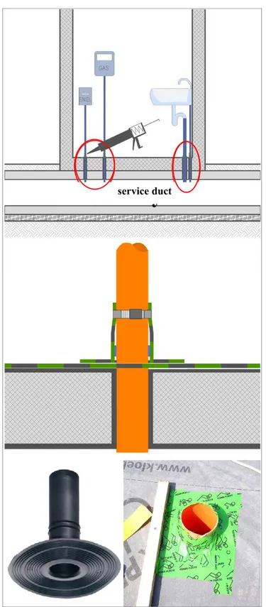
All mitigation and remedial techniques require to provide adequate sealing around vertical cavities and connections such as equipments pipes and ducts or the lift shaft. Especially underground ducts which provide domestic utilities are critical points because when they cross the ground floor slab, they can allow radon inflow. So all these discontinuity points have to be sealed using silicone, grip tape or the same rubber flange used in flat roof for drainage. Fig. 4 provides some examples.
Fig. 2 Examples of components to be used in realizing a suction point: (a) concrete well drilled and filled with gravel to enlarge the surface of the suction point; (b) bottomless concrete well (to be cover in the upper) connected to a fan/air extractor by a suction tube; (c) fan/air extractor directly located inside a bottomless concrete well.
Source: G. Zannoni.
(a)
(b)
Fig. 3 Examples of extracting pipes in a suction point.
Fig. 4 Examples of pipe holes sealed.
Source: G. Zannoni.
Fig. 5 Three different remedial techniques applied to different blocks of the same building.
4. Final Remarks
Feedback and experiences coming from case studies application and research activities in the field gave positive results concerning the mitigation and remedial techniques adopted. A number of mitigation techniques were tested in small and large buildings and a monitoring action was performed in order to assess the results especially in public buildings where authorities specifically required a compared study of indoor conditions before and after interventions.
The size and complexity of the building often required the adoption of two combined remedial techniques or to divide the building into separate sectors in which a specific remedial technique was provided [14] as shown in Fig. 5 series.
The most recurring techniques are the one based on the depressurization of crawl space and then the one based on the depressurization of the ground by a suction point. Some critical aspects were detected. The place where intervention is provided plays a crucial role in the effectiveness of the adopted techniques, but its choice represents a very difficult phase as the users and the households are usually more interested in reducing damages and discomfort than in achieving optimal results. On the one hand, this is due to the invasive character of several remedial technique and on the other hand, to a reduced awareness of the users and households towards the problem and the risk for health.
In high energy efficiency buildings, difficulties are increased by more complex stratifications composing the building envelope and the basement as well as by the strong relation between achieved energy savings and dispersions reduction.
In case of new construction, a bitumen membrane can be introduced in the ground floor stratification in order to avoid radon inflow from the ground: the principle is more or less the same of the measure adopted to prevent rising dump but requires a very careful application in order to avoid any discontinuity
point.
In case of refurbishment or energy retrofitting, a responsible approach towards radon problem is required. It has to be noted that when airtight sealing of leakages in the building envelope is pursued in order to fulfil energy savings requirements, any small element able to produce a depression effect inside the building (such as a chimneypot, an air extractor, or even an open windows) may produce a suction effect of the gas from the soil by the ground floor slab. As the importance of this effect is usually underestimated, this building element is not involved in major interventions in undergoing renovation.
However, it has to be remarked that avoiding air exchange between inside and outside has very relevant implications both on the energy and the radon issues as well.
Thus these issues cannot be faced separately, but focusing on indoor air quality which depends on several factors. So more specific requirements have to be introduced in building codes and regulations, as already done by some public administrations, in order to combine adequate radon proofing measures with energy saving principles especially when air tightness is assumed as a strategic design criteria. It finally may be said that health problems caused by indoor pollutants like radon should be more expensive than any energy bill.
Energy savings and sustainable policies are certainly a priority in the very next future, but many efforts are still required for making people aware of the importance of indoor air quality which is a very closed topic to near zero energy buildings.
References
[1] National Research Council. 1999. Health Effects of Exposure to Radon. Committee on Health Risks of Exposure to Radon: BEIR VI. Washington, DC: National Academy Press.
[2] UNSCEAR (United Nations Scientific Committee on the Effects of Atomic Radiation). 2000. Sources and Effects of Ionizing Radiation. Report to the General Assembly, with Annexes. United Nations, New York.
[3] International Agency for Research on Cancer (IARC), WHO. 1988. Monographs on the Evaluation of Carcinogenic Risks to Humans: Radon and Man-Made Mineral Fibres. Vol. 43. Lyon, IARC.
[4] Dubois, G. 2005. An Overview of Radon Surveys in Europe, EUR 21892 EN, Catalogue No.LB-NA-21892-EN-C-PB/2005/IES/1527. Luxembourg: Office for Official Publications of the European Commission.
[5] EU. 1990. 90/143/Euratom: Commission Recommendation of 21 February 1990 on the Protection of the Public against Indoor Exposure to Radon. Official Journal L 080, 27/03/1990 P. 0026-0028.
[6] Akerblom, G. 1999. Radon Legislation and National Guidelines. Swedish Radiation Protection Institute SSI, report 99:18.
[7] WHO. 2007. International Radon Project Survey on Radon Guidelines, Programmes and Activities. Geneva: WHO Press.
[8] WHO. 2009. WHO Handbook on Indoor Radon: A Public Health Perspective. Geneva: WHO Press. Accessed 2009. http://www.who.int/ionizing_radiation/env/radon/en/inde
x1.html.
[9] Zhang, Z. G., Smith, B., Steck, D. J., Guo, Q., and Field, R. W. 2007. “Variation in Yearly Residential Radon Concentrations in the Upper Midwest.” Health Phys. 93: 288-97.
[10] Zannoni, G., and Bigliotto, C. 2008. Gas Radon: Monitoraggio e Bonifica. Monfalcone: Edicom.
[11] Regione Lombardia—Sanità, ASL Lombardia, Arpa Lombardia, Dip. di Architettura—Ferrara. 2011. Linee Guida per la Prevenzione Delle Esposizioni al gas Radon in Ambienti Indoor, Milano. Accessed December 21, 2011. http://www.sanita.regione.lombardia.it/cs/Satellite?c=Red azionale_P&childpagename=DG_Sanita%2FDetail&cid= 1213289708526&pagename=DG_SANWrapper. (in Italian) [12] Scivyer, C. 2007. Guidance on Protective Measures for
New Buildings. Bracknell: Brepress.
[13] Scivyer, C., and Cripps, A. 1998. A BRE Guide to Radon Remedial Measures in Existing Dwellings. Bracknell: Brepress.
[14] Zannoni, G., Bellezza, M., Bigliotto, C., and Prearo, I. 2006. Gas Radon: Tecniche di Mitigazione. Monfalcone: Edicom.