Università degli Studi di Catania
Dottorato di Ricerca
in Scienza dei Materiali
XXV Ciclo (2009
Università degli Studi di Catania
“In Liquid” Laser
Processes for
Nanoparticles Synthesis
and Manipulation
Gabriele Carmine
Tutor:
Chiar.mo Prof. G. Compagnini Coordinatore:
Chiar.mo Prof. A. Licciardello
Dottorato di Ricerca
in Scienza dei Materiali
XXV Ciclo (2009-2012)
“In Liquid” Laser
or Metal
Synthesis
and Manipulation
Gabriele Carmine Messina
Chiar.mo Prof. G. Compagnini Chiar.mo Prof. A. Licciardello
CONTENTS... I
SCOPE OF THESIS... 1
CHAPTER 1: METAL NANOPARTICLES AND THEIR PROPERTIES ... 3
1.1 INTRODUCTION ... 3
1.2 OPTICAL PROPERTIES ... 5
1.2a Introduction to Mie Theory ... 9
1.2b Dipole Plasmon Resonance... 11
1.2c Quadrupole Plasmon Resonance ... 16
1.3 CHEMICAL PROPERTIES ... 17
1.4 PHYSICAL PROPERTIES ... 22
REFERENCES... ... 27
CHAPTER 2: PULSED LASER ABLATION IN LIQUID ... 33
2.1 INTRODUCTION ... 33
2.2 THE MECHANISM OF LASER ABLATION IN LIQUID ... 35
2.2a Plasma Formation... 35
2.2b Plasma Expansion ... 39
2.3 NANOCRYSTAL FORMATION BY LASER ABLATION IN LIQUID ENVIRONMENTS ... 48
2.3a Metals ... 48
2.3b Oxides and Sulfides ... 49
REFERENCES ... 54
CHAPTER 3: HIGH YIELD PRODUCTION OF METAL NANOPARTICLES BY WIRE ABLATION ... 63
3.1 INTRODUCTION ... 63
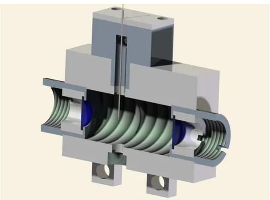
3.2 EXPERIMENTAL DETAILS ... 66
3.3 NORMALIZATION OF EFFICIENCY DATA ... 70
3.4 ABLATION EFFICIENCY ... 76
3.5 LASER INDUCED PLASMA ANALYSIS ... 82
3.6 CAVITATION BUBBLE INDUCED AFTER BULK ABLATION ... 90
3.7 WIRE BUBBLE DYNAMICS ... 96
3.8 EFFECT OF LASER ENERGY...1 06 3.9 EFFECT OF REPETITION RATE...1 11 REFERENCES...1 14 CHAPTER 4: INDUCED AND SPONTANEOUS JOINING OF METAL NANOPARTICLES...1 19 4.1 INTRODUCTION...1 19 4.2 AGGREGATION PHENOMENA IN SILVER NANOPARTICLES JOINED THROUGH HIGHLY CONJUGATED CARBON CHAINS...1 21 4.2a Laser Ablation of Carbon...122
4.2b Preparation of Nanoaggregates...124 4.2c Plasmon Resonance and Surface State...1 26
4.2d Simulation of Observed Plasmon Resonances...132 4.2e SERS Implications...1 35 4.3 MONITORING OF AGGREGATION OF
GOLD NANOPARTICLES IN LIQUID...1 41 4.3a Dynamic Light Scattering...1 44 4.3b UV-Vis Spectroscopy...1 50 REFERENCES...1 53 CHAPTER 5: ALLOYING OF METAL NANOPARTICLES…..1 61 5.1 INTRODUCTION...1 61 5.2 FORMATION OF Au/Ni SYSTEMS BY
LASER MIXING IN LIQUID ENVIRONMENT...1 64 5.2a Preparation of alloys...164 5.2b Characterization of alloys...165 REFERENCES...1 80 CONCLUSIONS...1 83 ACKNOWLEDEGMENTS...1 85
SCOPE OF THE THESIS
Last decades have seen an exponential spread of high level technology in everyday life. Leading trends of this explosion have been mainly two: miniaturization, since carrying a small device in a pocket means its daily use, and accessibility, because cheaper products can be afforded by larger audiences. The research of new materials able to fulfill these characteristics seems to be a logical consequence of these tendencies and probably one of the reasons for the increase of scientific interest into the nanotechnology field. Indeed, the possibility of applications of these intriguing structures in the construction of devices is becoming concrete. The step to the nanometric size involves the appearing of peculiar properties which are not present in the bulk state and this characteristic is of undeniable appeal for technological purposes. Among the large variety of different entities, metal nanoparticles are playing a major role because of their unique optical, electrical and antibacterial properties, which make them perfect candidates as base for the preparation of devices with applications in microelectronics, photonics and medical fields. In this regard, the need for pure, ligand-free nanoparticles with desired size and shape is a relevant problem both from the scientific and industrial point of interest. It is well known that Pulsed Laser Ablation in Liquid (PLAL) represents a universal technique for the preparation of innovative nanomaterials with desired characteristics. The simple variation of the nature of the target and the surrounding liquid allows the formation of a
large choice of different nanostructures, ranging from metal nanoparticles to oxides or carbon structures. Also the tuning of the laser parameters, such as energy and repetition rate, influences the characteristics of the obtained product. Furthermore, since the care of environment is becoming a topic of main interest, it should not be forgotten that laser ablation can be considered a green technique. Indeed, the absence of dangerous chemicals and the simple work conditions, such as room temperature and atmospheric pressure, point at this technique as environmentally friendly. For the reasons above, laser ablation seems to be an optimal candidate for the production of metal nanoparticles on large scale but, till now, the low production yield of this technique has stopped every attempt in this direction. In this view, the development of new strategies to increase the efficiency of laser ablation represents an interesting field of research. A study of the physics fundamentals of the process is also required in order to determine the parameters driving the efficiency variation. Nanoparticles produced by laser ablation in liquid could be used as pure or their properties can be enhanced by obtaining nanocomposites with different materials. Thus, the accurate characterization of the obtained material, together with a proper manipulation, are topics of primary importance.
CHAPTER 1: METAL
NANOPARTICLES AND THEIR
PROPERTIES
1.1 INTRODUCTION
The word nanocluster indicates an ensemble of atoms with dimensions varying from a few nanometers to a few hundreds. In this range of size, the increase of the ratio between the surface and the number of inner atoms is responsible for peculiar behaviours of the structure, leading to the appearance of several quantum properties which cannot be found in the bulk structure of the metal. The presence of these characteristics is appealing when considering the development of innovative materials. In this optic, metal nanoclusters can be considered as starting building blocks for the formation of larger structures with the same chemical nature or they can be mixed together with other materials such as polymers or inorganic materials to create new composites. The production of metal nanoparticles can be obtained by different techniques and the properties of the final product will depend on the chosen route. Conventionally, it is possible to distinguish between chemical and physical preparation methods even if, looking deeply at involved mechanisms, a marked boundary does not really exist. Chemical methods, often identified also as “wet” methods, since such approaches
work in liquid environment, are mainly based on the reduction of a precursor of the desired metal in aqueous or organic solutions. The Turkevitch method, developed in 1951, allows the preparation of gold nanoparticles with dimensions in the range of 10-100 nm, by the reduction of HAuCl4 in a boiling solution of sodium citrate [1]. The role
of citrate molecules is to act as reducing agents but also as stabilizers for nanoparticles. The same procedure can be applied for obtaining silver nanoparticles starting from AgNO3, but with limited size control [2].
Nanoparticles prepared by chemical methods can be functionalized with ligands, simply adding the proper molecule to the solution. The attachment of ligands with nanoparticles is usually achieved by the presence of a sulphur termination on the molecules, which is known to strongly interact with metals such gold and silver.
Physical approaches to preparation of nanoparticles generally involve the removing of material from a solid target by different methods, such as sputtering or vaporization (in the case of Physical Vapour Deposition). The material is then driven through a reactor by a carrier gas to a zone where nucleation and growth happens and then nanoparticles are deposited on a substrate, obtaining thin films.
A particular case is represented by Chemical Vapour Deposition, in which nanoparticles are grown from volatile precursors of the desired metal. Vaporised precursors are then introduced into a reactor and absorbed onto a substrate which is held at high temperature, where absorbed molecules will thermally decompose or react with other vapours to form crystals. Main disadvantages of physical techniques are
that obtained nanoparticles are bound to a substrate and that deposited films can be contaminated by bubbles due the presence of carrier gas. Among routes to obtain metal nanoparticles, a relevant role has been assumed by pulsed laser ablation (PLA). This approach, and in particular its variant in liquid, is indeed becoming the preparation of choice since presents a lot of advantages like the high purity of produce obtained nanoparticles, the applicability to almost all metals, the relative low cost and the eco-compatibility.
1.2 OPTICAL PROPERTIES
The smoothed surface of metals in bulk state presents a shiny appearance, and this behaviour is attributed to the total reflection of light due to the high density of electrons in the material. Contrariwise, finely divided metals look dark, because the large surface absorbs light through repeated reflection phenomena [3]. When metals reach nanometer size, strong absorption of light can happen when the frequency of the electromagnetic field becomes resonant with the coherent electron movement [4]. In the case of Au, Ag and Cu, which present free conduction electrons with plasma frequency in the visible region, nanoparticles appear colored [5]. Other transition metals, instead, show only broad and poorly resolved absorption bands in the ultraviolet region [4]. This singular characteristic is known and used since ancient times. Indeed, first evidences of colloidal solution of gold have been found in
the 5th and 4th century B.C. in Egypt and China, probably used for coloring glass and ceramics [6]. Among ancient artifacts, one of the most famous examples is the so-called “Lycurgus cup”, a glass vessel which appears green in reflected light and red in transmitted light, dated 4th century A.D [7]. The nice visual effect of the cup has been attributed to the presence of a mixture of gold and silver colloids (with size ~70 nm) embedded in the glass matrix [5].
Figure 1.1 Views of the “Lycurgus cup” in (a) reflected and (b) transmitted light. From ref. [7].
Metal nanoparticles were also used during the Middle Ages for the fabrication of stained glass in cathedrals [8].
The first analytical approach to optical properties of gold particles in hydrosols can be recognized to Michael Faraday, with his 1857 article “Experimental Relations of Gold (and other Metals) to light”
attributes the ruby color to the presence o
solution, obtained reducing dilute gold chloride with phosphorus and tartaric acid or by heating, and widely discusses about size dependent optical properties and coagulation behavio
such as platinum, mercury, arsenic.
properties of metal nanoparticles are due to the presence of a collective longitudinal excitation of conduction electron
nanoparticle
Figure 1.2 Schematic representation of the electronic cloud as consequence of an oscillating electric field
The first analytical approach to optical properties of gold particles in hydrosols can be recognized to Michael Faraday, with his 1857 article “Experimental Relations of Gold (and other Metals) to light”
attributes the ruby color to the presence of “finely dispersed” gold in solution, obtained reducing dilute gold chloride with phosphorus and tartaric acid or by heating, and widely discusses about size dependent optical properties and coagulation behaviour of gold and other metals platinum, palladium, rhodium, silver, tin, lead, zinc, iron, mercury, arsenic. Today is widely known that the color and optical properties of metal nanoparticles are due to the presence of a collective longitudinal excitation of conduction electrons on the surface
s, known as Surface Plasmon Resonance (SPR)
Schematic representation of the electronic cloud as consequence of an oscillating electric field.
The first analytical approach to optical properties of gold particles in hydrosols can be recognized to Michael Faraday, with his 1857 article “Experimental Relations of Gold (and other Metals) to light” [9]. He f “finely dispersed” gold in solution, obtained reducing dilute gold chloride with phosphorus and tartaric acid or by heating, and widely discusses about size dependent r of gold and other metals palladium, rhodium, silver, tin, lead, zinc, iron, Today is widely known that the color and optical properties of metal nanoparticles are due to the presence of a collective on the surface of the , known as Surface Plasmon Resonance (SPR) [10].
According to the Fermi liquid model, it is possible to consider a plasmon as a negatively charged electron cloud displaced from its equilibrium position around a lattice made of positively charged ions, similarly to real plasma.
This phenomenon can be described with an electrostatic model that assumes the approximation of surface electrons (with number density N and charge e) to a monodimensional slab.
If an electric field Eapp is applied to the slab, it generates a force that can
be written as:
= − (1.1) Then, the charge is moved from its initial position of a displacement x and the total surface density at each end of the slab will be:
= (1.2) According to Gauss’s law, the field created between two surface charges is given by:
= (1.3) where ε0is the vacuum dielectric permittivity.
The presence of this field creates a restoring force opposite to the one described in eq. (1.1):
= − = − (1.4) and so electrons will move according to:
= = − (1.5) where m is the electron effective mass.
= − (1.6) and solution to this equation is given by:
= cos (1.7) with characteristic oscillation frequency
ω
p:= (1.8) Qualitatively, the irradiation of a metal nanoparticle by the oscillating electric field of light causes the coherent oscillation of conduction electrons. When the electron cloud is displaced from the nuclei, the coulomb attraction between electrons and nuclei produces a restoring force that results in oscillation of the electron cloud relative to the nuclei. The oscillation frequency depends on the density of electrons, the effective electron mass and shape and size of charge distribution.
1.2a Introduction to Mie Theory
In 1908, Mie wrote a seminal paper titled “Beiträge zur Optik trüber Medien, speziell kolloidaler Metallösungen” (literally “Contributions on the optics of turbid media, particularly colloidal metal solutions”) [11], in which he presented a solution to Maxwell’s equations that describes the extinction spectra (where extinction is a term that includes scattering and absorption contributes) of spherical particles of arbitrary size. Even though the Mie model is relatively aged, it still remains of great interest being the only simple, exact solution to Maxwell’s equations that is relevant to describe nanoparticles behaviour [12]. Anyway, the pure Mie
approximation in general is not accurate enough to describe real situations, since the presence of complicating factors in understanding the nanoparticle optical properties, including the presence of a supporting substrate, a solvent layer on the top of nanoparticles, or particles close enough to lead to electromagnetic couplings [12]. Later, Gans [13] extended the theory to spheroid particles, showing how smaller non spherical particles can show absorbance at longer wavelength respect to sphere of the same dimension.
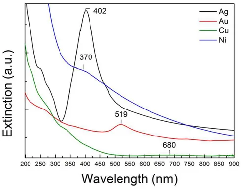
Figure 1.3 UV-Vis spectra showing the SPR peaks of silver, gold, copper and nickel colloidal solutions obtained by laser ablation of pure metals in water.
1.2b Dipole Plasmon Resonance
The plasmon resonance phenomenon has been widely discussed in literature [12,14-15].
The most common approach correlates the plasmon frequency with the metal dielectric constant, which is a property that can be measured as a function of wavelength for bulk metals. Considering the interaction of light with a spherical particle smaller than the wavelength of the light, the electric field of light can be taken as constant, so the interaction is governed by electrostatics rather than electrodynamics. This is often called the quasi-static approximation, as the wavelength-dependent dielectric constant of the metal particle, εi and the surrounding medium
εmare used in what is otherwise an electrostatic theory.
The electric field of the incident electromagnetic wave is denoted by the vector E0, which is constant in the x direction so that it can be written as:
= (1.9) where is a unit vector.
The electromagnetic field surrounding the particle is determined by solving Laplace’s equation
∇ = 0 (1.10) where φ is the electric potential.
The electromagnetic field E is related to the potential φ by the equation: = −∇ (1.11) In developing this solution, two boundary conditions are applied:
- The normal component of the electric displacement D is also continuous, where D=εE.
General solution to the Laplace’s equation presents angular solutions which are just the spherical harmonics. In addition, the radial solutions are of the form rl and r-(l+1) where l is the familiar angular momentum
label (l=0,1,2,…) of atomic orbitals.
Considering just the l=1 solution and the field E0 in the x direction, the
potential inside a sphere of radius R (where r<R) is given by:
= sin cos (1.12) while outside the sphere (r>R) it will be:
= (− + / )sin cos (1.13) where A and B are constants to be determined.
Inserting these solutions into the boundary conditions and using the resulting potential φ to determine the field outside the sphere Eout, it is
possible to deduce:
= − − ( + + ̂) (1.14)
Where α is the sphere polarizability and , and ̂ the unit vectors. In eq. (1.14) the first term represents the applied field while the second one represents the induced dipole field (with induced dipole moment given by αE0) that results from polarization of the conduction electron
density.
For a sphere with the dielectric constant εi in a medium with dielectric
constant εm, the solution to Laplace equation shows that the polarizability
is given by:
with
= (1.16) Although the dipole field in eq. (1.14) is that for a static dipole, the complete Maxwell’s equation solution shows that this is actually a radiating dipole, and thus, it contributes to extinction and Rayleigh scattering by the sphere. From this it is possible to deduce the extinction and scattering efficiencies as:
= 4 ( ) (1.17) = | | (1.18) where
= (1.19)
The efficiency is the ratio of the cross section to the geometrical cross-section πR2as described by:
= (1.20) The factor gd plays the key role in determining the wavelength
dependence of these cross-sections, as the metal dielectric constant εi is
strongly dependent on wavelength.
The extinction cross section Cext is useful when predicting the absorption
of small particles, since the attenuation of light in a dilute colloidal solution is given by [16]:
(ℓ)= − (ℓ) (1.21)
Where N is the number density of particles, I0 is the intensity of light, ℓ is
Integration of eq. (1.21) gives the optical absorption of the solution: = log (ℓ) . (1.22) For small spherical particles (2R<<λ, where the dipole approximation is still valid), with a complex frequency-dependent dielectric function εi=
ε’+ iε’’, embedded in a medium of dielectric function εm, the extinction
cross section is expressed by [11,17-20]:
= / ′′
( ′ ) "′ (1.23)
This equation predicts the existence of an absorption peak when ε’(ω)
=-2εm, while ε” is small or weakly dependent from ω [5,21].
It is also possible to notice that no absorption is contemplated for two opposite values of the imaginary part of the dielectric function, since the cross section assumes a zero value if ε’’=0 (non absorption case) but also if ε’’=∞ (complete reflection of light) [16].
Cext depends on R3, while the number density decreases as R3 for a given
amount of colloidal material. Therefore the absorption coefficient is independent of particle size [16].
Nevertheless, a dependence on the size has been observed experimentally [14]. This discrepancy arises from the assumption in the Mie theory that the electronic structure and dielectric constant of nanoparticles are the same as those of its bulk form, which becomes no longer valid when the particle size becomes very small [21].
Indeed in small particles, electron surface scattering becomes significant [22-24], because the mean free path of conduction electrons (40-50 nm in silver and gold [25]) is bigger than the physical dimension of the
particles themselves. The scattering of electrons with the surface in an elastic but random way will cause the loss of coherence of the overall plasmon oscillation. Also inelastic electron surface collisions will contribute to the change of the phase. This can be taken in account changing the dielectric constant of the particles, which becomes size dependent [14,21-24], and an increase of the plasmon bandwidth results at the decreasing of the particle size. When the dimensions of nanoparticles further decrease, and the nanoparticles size is comparable to de Broglie’s wavelength of an electron at the Fermi energy (diameters of 1-2 nm), the surface plasmon band disappears [26-28] because the assumption of a delocalized electronic gas is no longer valid and particles should be treated as molecular clusters with discrete electronic levels. Therefore it is possible to observe fluorescence emission due to optical transitions between single electronic states [21].
On the other way, for larger particles the dipole approximation is no longer valid and it is necessary to consider also higher order oscillations, which give a size dependence of the plasmon band position (that shows a red shift with increasing diameter) as well as an increase in the bandwidth [12].
Figure 1.4 UV-Vis spectra of spherical Au nanoparticles with different sizes ranging from 9 to 99 nm, showing variation of the SPR peak on dimensions. From ref. [29].
1.2c Quadrupole Plasmon Resonance
Among higher modes of plasmon excitation it is worth discussing the quadrupole mode (l=2), where half of the electron cloud moves parallel to the applied field and half moves antiparallel [12]. Using the same notation used for the dipole plasmon resonance and including the l=2 term in the Laplace equation solution, the resulting field outside the sphere, Eout, can be expressed as:
= + ( + ̂) − − ( + + ̂ −
̂− ( + + ̂ (1.24)
and the quadrupole polarizability is given by:
= (1.25) with
= / (1.26) The presence of a factor 3/2 at the denominator of eq. (1.26) instead of the factor 2 present in eq. (1.16) derives from the exponents in the radial solutions to Laplace’s equation, that are the factors rl and r-(l+1). In the
cases of dipole excitation, we have l=1, and the magnitude of the ratio of the exponents is (l+1)/l=2, while for quadrupole excitation it becomes (l+1)/l=3/2. Following the same derivation, the quasistatic expressions including the dipole and the quadrupole contributions for the extinction and Rayleigh scattering efficiencies are:
= 4 + + ( − 1) (1.27)
= | | + + | − 1| (1.28)
1.3 CHEMICAL PROPERTIES
The high surface to volume ratio deriving from the reduced size is the leading parameter in the description of the chemical behaviour of metal nanoparticles. This consideration is due to the fact that surface atoms
often show the presence of unsaturation or dangling bonds and as result, higher chemical reactivity [4]. In general, noble metals such as gold and silver are inert and as a consequence, metal nanoparticles are stable in ordinary condition [30]. For this reason, laser prepared noble metal nanoparticles present pure surface and this characteristic is of huge importance for applications such catalysis, where surface plays a fundamental role. Indeed, necessary condition for a catalytic process is the absorption of reactants on the catalyst, and this happens at surface sites, lattice defects and corners or edge of crystallites. It is straightforward that dimension of the particles is relevant for the reactivity, since the decrease of the dimension leads to an increase of surface sites [31]. Moreover, surface atoms of small particles are dynamically active with the possibility of surface reconstruction phenomena [32]. It has been found that the activity of tetrahedral shaped Pt nanoparticles, used for catalyzing electron-transfer reaction, decreases during the course of the reaction as a result of morphological changes toward a spherical shape, which present the most stable surface [33]. If nanoparticles are used in homogeneous catalysis, there is the need to protect their surface with a stabilizer, usually a polymer like PVP [34], in order to prevent aggregation phenomena and to allow their recycle, but it has been demonstrated that the presence of capping decreases the catalytic activity since surface sites are occupied by the capping molecules [35].
A role of interest is covered by palladium since it is an excellent hydrogenation catalyst but it catalyzes as well the formation of a large
variety of C-C bonds [36-37]. Gold nanoparticles present excellent catalytic properties too, and have been used to catalyze the oxidation of CO to CO2 [38-41], and other reactions [42].
Also less noble metals clusters, like iron nanoparticles, have found application in the catalysis field [43].
Among metal oxides, TiO2 nanoparticles are attracting several attentions
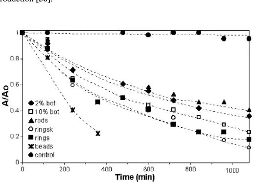
for their unique photo-properties [44]. The peculiar electron transport of these nanoparticles can be used for different purposes such as water purification [45-48], bactericidal coatings [48-49] and hydrogen production [50].
Figure 1.5 Photocatalytic degradation of 4-chlorophenol due to solar irradiation of TiO2 nanoparticles deposited on different ceramic supports
Metal nanoparticles present also interesting applications in the biological field. For example, silver nanoparticles show bactericidal properties as a result of their surface chemistry.
It is well known that silver exhibits strong toxicity to a wide range of microorganism [51] and for this reason silver based compounds have been used in many bactericidal systems [52-53]. Silver compounds have also been used in the medical field to treat burns and a variety of infections [54].
The effect is due to the fact that exposition to atmospheric oxygen leads to surface oxidation and subsequent releasing of Ag+ ions, which interfere with bacterial metabolism [30].
The mechanism is not completely understood yet, but it has been proposed that ionic silver strongly interacts with thiol groups of vital enzymes and inactivate them [55-56] or that DNA loses its replication ability once the bacteria have been treated with silver ions [54]. In literature are reported also experimental evidences of structural changes in the cell membrane as well as the formation of small electron-dense granules formed by silver and sulphur [54, 57].
However, recent studies have demonstrated that silver ions at concentration required to show germicidal effects, also damage fibroblasts to a significant degree [58-59]. For this reason, the application of silver nanoparticles to therapeutic purposes should be accurately targeted [58-59].
Figure 1.6 Bactericidal effects of laser-generated silver nanoparticles on Staphylococcus aureus after in vitro cultivation on Mueller-Hinton agar plates with or without BSA (1% w/v) over 24 h. From ref. [58].
Gold and silver nanoparticles are also strongly reactive with sulphur and this characteristic is of particular interest for the functionalization of particle surface in biological studies [60]. Indeed, thiolated biomolecules can be directly bound on the surface of nanoparticles, like oligonucleotides [61], peptides [62] or PEG [63]. Literature also reports the formation of gold nanoparticles-DNA aptamers used for the detection of thrombin [64], platelet-derived growth factors [65] and cancerous cells [66].
1.4 PHYSICAL PROPERTIES
The reduction of size and the subsequent increase in percentage of surface atoms is also responsible for the variation of physical properties from bulk to nanostructured particles. It has been demonstrated that phase stability of a material is size dependent [67].
By simple thermodynamic considerations, the total free energy of a nanoparticle can be expressed as the sum of free energy contribution of the bulk and the surface [67]:
= + (1.29) In a system such as a nanoparticle, which contains only few hundreds of atoms, a large fraction of them will be located on the surface. Surface atoms tend to be coordinatively unsaturated, so there is a large energy associated with the surface and the second term of eq. (1.29) becomes important for the overall phase stability [4].
For example, in TiO2 nanoparticles with dimension lower than 14 nm,
anatase phase showed more stability than rutile, which is instead more stable in the case of bulk titanium dioxide [68].
Another well known example of variation of physical properties with size is the decrease of melting temperature when passing from bulk to nanoclusters, with the value of the temperature depending on the size, shape and composition of the nanostructure. This phenomenon can be understood considering that liquid phase always shows lower surface energy with respect to the solid phase, where atoms are constrained by rigid bonding geometries. During the passage to the dynamic fluid phase,
the movement of surface atoms promotes the minimizing of the surface area and unfavorable surface interactions. Thus, the melting phenomenon reduces surface energy and stabilizes the liquid phase. Since at reduced dimensions the contribution of surface energy increases, the melting point shows considerable reductions [4].
The estimation of the melting point can be obtained by the following relationship [69]:
= − (1.30) Where Tm is the melting temperature of the nanoparticle, Tb is the melting
point of the bulk metal, R is the radius of the nanoparticle and M is a constant which depend on the material in specified conditions.
Recently a model for calculating the reduction of melting temperature which also takes in account the shape factor has been proposed [70]. The melting temperature of a nanoparticle of any shape is given by [70]:
= 1 − 6 (1.31) Where α is the shape factor, is the atomic radius and D is the diameter of the nanoparticle (D=2R).
The shape factor α is given by:
= (1.32) where S’ is the surface of a particles of any shape which presents the same volume of a spherical particle of surface S.
Qualitatively, this can be explained considering that since melting starts at the surface, a larger surface will favour this process, and the melting point will present a lower value [71-72].
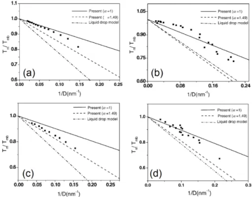
Figure 1.7 Calculated variation of the melting temperature as a function of the inverse radius for (a) Sn (b) Pb (c) In (d) Bi nanoparticles. The symbols (■) represent experimental values from ref. [70].
When nanoparticles reach the size of few nanometers, which is smaller than the de Broglie wavelength of electrons at the Fermi energy for most metals, quantum effects appear in nanoparticles [73] and this leads to variations of the conductivity from the bulk behaviour.
Indeed, once the band electronic level turns into discrete electronic level, the motion of electrons does not obey the Ohm’s law which instead rules bulk metals [4].
To transfer an electron to a nanoparticle it is necessary to give to the system an energy called charge energy:
= (1.33) where e is the charge of an electron and C the capacitance of the nanoparticle.
For a nanocluster surrounded by a medium with dielectric constant ε, the capacitance of the nanoparticle depends on its size:
( ) = 4 (1.34) where R is the radius of the nanoparticles.
From eq. (1.33) and (1.34) it is clearly visible that high amount of energy required to add a single charge to a metal nanoparticle because capacitance is very low as it decreases with the decreasing radius. Qualitatively this can be explained considering that a charge carrier is no longer solvated in an effectively infinite medium [4].
To produce single-electron tunneling processes, the thermal energy of the particle must be much lower than the coulomb energy in order to keep the electron in the particle:
≪ (1.35) where kB is the Boltzmann constant and T is the temperature of the
system.
Otherwise the electron will be able to pass the nanoparticle by thermal excitation.
The current-voltage diagram for an ideal quantum dot will not show current till the potential reaches the value:
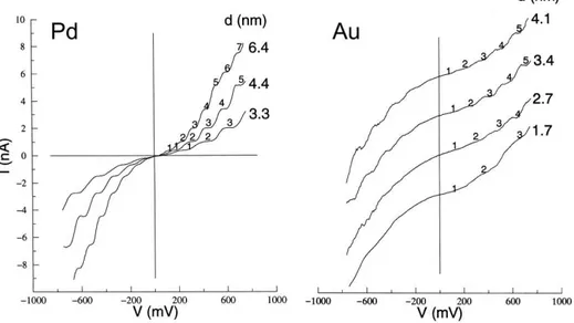
And then an electron can be transferred. The charging of the nanocrystal occurs in increments of single electrons, giving rise to staircase with equally spaced steps in the I–V spectrum [74].
Since for each step the charge transport is blocked till the overcoming of the Coulomb potential, this phenomenon is called Coulomb blockade.
Figure 1.8 Current-Voltage diagrams of isolated Pd and Au nanoclusters of different sizes showing the Coulomb staircase effect. From ref. [74].
REFERENCES
[1] J. Turkevich, P.C. Stevenson, J. Hillier, Discuss. Faraday Soc., 1951, 11, 55-75
[2] Z.S. Pillai, P.V. Kamat, J. Phys. Chem. B, 2004, 108, 945-951
[3] G. Schmid, in “Nanoscale Materials in Chemistry”, K.J. Klabunde, R.M. Richards (Eds.), Wiley: New York, 2009, p. 19
[4] C. Burda, X. Chen, R. Narayanan, M.A. El-Sayed, Chem. Rev., 2005, 105, 1025-1102
[5] L.M. Liz-Marzan, Mater. Today, 2004, 7, 26-31
[6] M.C. Daniel, D. Astruc, Chem. Rev., 2004, 104, 293-346
[7] http://www.britishmuseum.org/explore/highlights/highlight_objects/ pe_mla/t/the_lycurgus_cup.aspx
[8] C.P. Poole Jr., F.J. Owens, “Introduction to Nanotechnology”, Wiley: New York, 2003, p. 72
[9] M. Faraday, Phil. Trans. R. Soc. London, 1857, 147, 145-181
[10] C. Kittel, "Introduction to Solid State Physics", Wiley: New York, 1996.
[11] G. Mie, Ann. Phys., 1908, 25, 377–445
[12] K.L. Kelly, E. Coronado, L.L. Zhao, G.C. Schatz, J. Phys. Chem. B, 2003, 107, 668-677
[13] R. Gans, Ann. Phys., 1912, 37, 881–900
[14] U. Kreibig, M. Vollmer, “Optical Properties of Metal Clusters” Springer Series in Materials Science 25, Springer: Berlin, 1995.
[15] U. Kreibig, in: R.E. Hummel, P. Wissmann (Eds.), “Handbook of Optical Properties; Vol. II: Optics of Small Particles,Interfaces and Surfaces”, CRC Press:Boca Raton, 1997, pp 145-190
[16] J. Pérez-Juste, I. Pastoriza-Santos, L.M. Liz-Marzán, P. Mulvaney,
Coord. Chem. Rev., 2005, 249, 1870–1901
[17] H.C. van der Hulst, “Light Scattering by Small Particles”, John Wiley and Sons: New York, 1957
[18] M. Kerker, “The Scattering of Light and Other Electromagnetic Radiation”, Academic Press: New York, 1969
[19] L. Genzel, T.P. Martin, U. Kreibig, Z. Phys. B, 1975, 21, 339-346. [20] C.F. Bohren, D.F. Huffman, “Absorption and Scattering of Light by Small Particles”, Wiley: New York, 1983
[21] S. Link, M.A. El-Sayed, Annu. Rev. Phys. Chem., 2003, 54, 331–366 [22] U. Kreibig, U. Genzel, Surf. Sci., 1985, 156, 678-700
[23] U. Kreibig, C. von Fragstein, Z. Phys., 1969, 224, 307-323 [24] U. Kreibig, Z. Phys., 1970, 234, 307-318
[25] N.W. Ashcroft, N.D. Mermin ND., “Solid State Physics”, Saunders College: Philadelphia, 1976
[26] M.M. Alvarez, J.T. Khoury, T.G. Schaaff, M.N. Shafigullin, I. Vezmar, R.L. Whetten, J. Phys. Chem. B, 1997, 101, 3706-3712
[27] T.G. Schaaff, M.N. Shafigullin, J.T. Khoury, I. Vezmar, R.L. Whetten, W.G. Cullen, P.N. First, C. Gutiérrez-Wing, J. Ascensio, M.J. Jose-Yacamán, J. Phys. Chem. B, 1997, 101, 7885-7891
[28] M.J. Hostetler, J.E. Wingate, C.J. Zhong, J.E. Harris, R.W. Vachet, M.R. Clark, J.D. Londono, S.J. Green, J.J. Stokes, G.D. Wignall, G.L.
Glish, M.D. Porter, N.D. Evans, R.W. Murray, Langmuir, 1998, 14, 17-30
[29] S. Link, M.A. El-Sayed, J. Phys. Chem. B, 1999, 103, 4212-4217 [30] N.N. Greenwood, A. Earnshaw, “Chemistry of the Elements”, Elsevier Science: Oxford, 1997
[31] A. Wieckowski, E.R. Savinova, C.G. Vayenas (Eds.), “Catalysis and Electrocatalysis at Nanoparticle Surfaces”, Marcel Dekker: New York, 2003, p. 970
[32] R. Narayanan, M.A. El-Sayed, J. Phys. Chem. B., 2004, 108, 5726– 5733
[33] R. Narayanan, M.A. El-Sayed, J. Am. Chem. Soc., 2004, 126, 7194– 7195
[34] N. Toshima in “Fine Particles Sciences and Technology – From Micro - to New Particles”, E. Pellizzetti (Ed.), Kluwer : Dordrecht ,1996, pp. 371 – 383
[35] Y. Li, M.A. El-Sayed, J. Phys. Chem. B, 2001, 105, 8938-8943 [36] D. Astruc in “Nanoparticles and Catalysis”, D. Astruc (Ed.), Wiley: New York, 2008, pp. 1-48
[37] D. Astruc, Inorg. Chem., 2007, 46, 1884-1894
[38] M. Haruta, T. Kobayashi, H. Sano, N. Yamada, Chem. Lett., 1987, 2, 405-408
[39] M. Haruta, N. Yamada, T. Kobayashi, S. Iijima, J. Catal., 1989, 115, 301-309
[40] M. Haruta, S. Tsuboda,T. Kobayashi, H. Kagehiama, M.J. Genet, B. Demon, J. Catal., 1993, 144, 175-192
[41] M. Haruta, CATTECH, 2002, 6, 102-115 [42] D.T. Thompson, Nano Today, 2007, 2, 40–43 [43] J. G. De Vries, Dalton Trans., 2006, 3, 421-429
[44] J.A. Anta, Curr. Opin. Colloid Interface Sci., 2012, 17, 124-131 [45] C. Wei, W.Y. Lin, Z. Zainal, N.E. Williams, K. Zhu, A.P. Kruzic, R.L. Smith, K. Rajeshwar, Environ. Sci. Technol., 1994, 28, 934-938 [46] Y. Chen, K. Wang, L. Lou, J. Photochem. Photobiol. A, 2004, 163, 281–287
[47] J.M. Meichtry, H,J. Lin, L. de la Fuente, I.K. Levy, E.A. Gautier, M.A. Blesa, M.I. Litter, J. Sol. Energy Eng., 2007, 129, 119-126
[48] P.C. Maness,S. Smolinski, D.M. Blake, Z. Huang, E.J. Wolfrum, W.A. Jacoby, Appl. Environ. Microbiol., 1999, 65, 4094–4098
[49] G. Fu, P.S. Vary, C.T. Lin, J. Phys. Chem. B, 2005, 109, 8889-8898 [50] M. Ni, M.K.H. Leung, D.Y.C. Leung, K. Sumathy, Renew. Sustain.
Energ. Rev., 2007, 11, 401–425
[51] S.Y. Liau, D.C. Read, W.J. Pugh, J.R. Furr, A.D. Russell, Lett. Appl.
Microbiol., 1997, 25, 279–283
[52] K. Nomiya, A. Yoshizawa, K. Tsukagoshi, N.C. Kasuga, S. Hirakawa, J. Watanabe, J. Inorg. Biochem., 2004, 98, 46–60
[53] A. Gupta, S. Silver, Nat. Biotechnol. 1998, 16, 888-890
[54] Q. L. Feng, J. Wu, G.Q. Chen, F.Z. Cui, T.N. Kim, J.O. Kim, J.
Biomed. Mater. Res., 2000, 52, 662–668
[55] Y. Matsumura, K. Yoshikata, S. Kunisaki, T. Tsuchido, Appl.
[56] A. Gupta, M. Maynes, S. Silver, Appl. Environ.Microbiol., 1998, 64 5042–5045
[57] L. Nover, K.D. Scharf, D. Neumann, Mol. Cell. Biol., 1983, 3, 1648–55
[58] S. Grade, J. Eberhard, A. Neumeister, P. Wagener, A. Winkel, M. Stiesch, S. Barcikowski, RSC Adv., 2012, 2, 7190-7196
[59] S. Grade, J. Eberhard, P. Wagener, A. Winkel, C.L. Sajti, S. Barcikowski, M. Stiesch, Adv. Eng. Mater., 2012, 14, B231–B239 [60] R.K. DeLong, C.M. Reynolds, Y. Malcolm, A. Schaeffer, T. Severs, A. Wanekaya, Nanotech. Sci. Appl., 2010, 3, 53–63
[61] W. Chen, A. Bian, A. Agarwal, L. Liu, H. Shen, L. Wang, C. Xu, N.A. Kotov, Nano Lett., 2009, 9, 2153–2159
[62] R. Lévy, Z. Wang, L. Duchesne, R.C. Doty, A.I. Cooper, M. Brust, D.G. Fernig, Chem. Bio Chem., 2006, 7, 592–594
[63] H. Otsuka H, Y. Nagasaki, K. Kataoka, Adv. Drug Deliv. Rev., 2003, 55, 403–419
[64] H. Cho, B.R. Baker, S. Wachsmann-Hogiu, C.V. Pagba, T.A. Laurence, S.M. Lane, L.P. Lee, J.B.H. Tok, Nano Lett., 2008, 8, 4386– 4390
[65] C.C. Huang, Y.F. Huang, Z. Cao, W. Tan, H.T. Chang, Anal. Chem., 2005, 77, 5735–5741
[66] C.D. Medley, J.E. Smith, Z. Tang, Y. Wu, S. Bamrungsap, W. Tan,
Anal Chem., 2008, 80, 1067–1072
[67] V.H. Grassian J. Phys. Chem. C, 2008, 112, 18303-18313 [68] H.Z. Zhang, J.F. Banfield, J. Mater. Chem., 1998, 8, 2073-2706
[69] P. Pawlow, Z. Phys. Chem., 1909, 65,1-35
[70] W.H. Qi, M.P. Wang, Mater. Chem. Phys., 2004, 88, 280–284 [71] P.R. Couchman, W.A. Jesser, Nature, 1977, 269, 481-483
[72] F. Ercolessi, W. Andreoni, E. Tosatti, Phys. Rev. Lett. 1991, 66, 911-914
[73] M.J. Madou, “Fundamentals of Microfabrication and
Nanotechnology, (Vol. 1) : Solid-State Physics, Fluidics, and Analytical Techniques in Micro- and Nanotechnology”, CRC Press: Boca Raton, 2011, p. 365
[74] P. John Thomas, G.U. Kulkarni, C.N.R. Rao, Chem. Phys. Lett., 2000, 321, 163–168
CHAPTER 2: PULSED LASER
ABLATION IN LIQUID
2.1 INTRODUCTION
The term laser ablation refers to the removal of material from a solid target by incidence of light. The laser pulse presents a penetration depth which depends on the laser wavelength and the refraction index of the material, typically with values around 10 nm. The expulsion of material from the target is due to different mechanisms [1].
At high energy flux, the ejected matter is typically converted into plasma, formed by atoms, molecules, ions, electrons, clusters and particulates in a physical state characterized by high temperature, high pressure and high density [2-3].
The difference of pressure between the plasma and the surrounding environment leads to the nearly adiabatic expansion of the plasma [4] and in particular conditions, materials from the target can condense and form nanostructures [5].
This process has been used for different purposes, such the pulsed laser deposition (PLD), where laser is used to vaporize material from a target in vacuum or in a carrier gas that is then deposited on a suitable substrate to obtain thin films, with lower cost and higher purity with respect to other techniques [6-7].
The removal of material due to ablation can be also used for surface cleaning, with applications both in technological field than in preservation and restoration of artworks [8]. It is common to make difference between “dry laser cleaning”, in which material is directly removed by absorption of light and “steam laser cleaning” obtained by submerging the substrate in a liquid environment. The substrate is then covered by a thin liquid layer which, irradiated by light, undergoes violent boiling, and the pressure generates from the explosion of bubbles removes the material [8].
The mechanism of laser ablation is also the base of different characterization techniques, such as MALDI (Matrix Assisted Laser Desorption/Ionization) mass spectrometry [9] or LIBS (Laser Induced Breakdown Spectroscopy) [10].
In the field of nanomaterials synthesis, laser ablation in liquid environment is of particular interest for several reasons. First of all, it can be considered an almost universal preparation technique, since the variation of the target material and the surrounding liquid can lead to the formation of a large variety of products, and size and shape of obtained nanocrystals can be tuned by the variation of laser parameters such as fluence and laser wavelength. Moreover, laser ablation in liquid leads to clean surface nanoparticles, an important requirement when these nanostructures are employed in the production of nanocomposites. Moreover, laser ablation in liquid can be considered as environmentally friendly and cheap with respect to other production techniques. Indeed, it
does not need the use of dangerous chemicals or the use of expensive and energy consuming pressure or temperature apparatuses.
2.2 THE MECHANISM OF LASER ABLATION IN
LIQUID
2.2a Plasma Formation
Conventionally, the phenomenon of laser ablation starts when light hits the target. The energy coming from the laser is absorbed by the material and couples with electrons in valence and conduction bands. If the energy is higher than a certain threshold, which depends on the material itself, breaking of electron bonds is possible with subsequent removing of material [11]. Optical energy is also redistributed by carrier-carrier, carrier-phonon and phonon-phonon interactions. The energy relaxation time presents the same order of time required to approach thermal energy distributions, which are Fermi-Dirac for electrons and Bose-Einstein for phonons. For metal and semiconductors, energy thermalisation times are of the order of 10-12 to 10-11 seconds [12].
When using femtosecond laser pulses, common values of laser irradiance (1013 W/cm2) are higher than ionization threshold, that thus takes place before the expulsion of the material [1]. This is a non-equilibrium process, since the pulse duration is shorter than relaxation phenomena and the lattice remains “cold” [13].
It is also possible that electrons with sufficient kinetic energy will move away from the solid before starting the thermalisation of the lattice [14]. A resulting charge separation is then established and ions will be ejected from the target, either by Coulomb explosion [15] or by electrostatic ablation [16].
In the case of fs ablation, the amount of ablated material depends only on the penetration depth and the diameter of the laser beam and the crater left by the beam present well defined borders [17-18].
On the other way, when nanosecond lasers are used, the pulse duration overpasses the time for reaching the system thermalisation through electron collisions and thermal conduction phenomena. Ions and electrons are accelerated by mutual collisions inside the plasma, and its temperature reaches the equilibrium [19-21].
The main mechanism of ablation is thermal ablation, which is direct sublimation or melting followed by evaporation, boiling or phase explosion, but also spallation [19,22-23].
Confirmations of thermal ablation during laser processes have been obtained by shadowgraph images that show the ejection of metal droplets from the target in the case of nanosecond pulses [24-25] and millisecond pulse width [26].
In the case of picosecond laser pulses, a complete understanding of involved phenomena is not clear yet and the ablation mechanism depends on the thermal characteristic of the metal [27]. Different models have been proposed to explain the behaviour under low fluence [28] and high fluence [29] regimes.
Figure 2.1 Shadowgraph image of laser ablation of an Ag target in water at a laser fluence of 36 J/cm2 and a delay time of 10 µs showing the ejection of metal nanodroplets from the target. From ref. [24].
Independently of the pulse width, when the irradiance of the laser exceeds a certain threshold, the “breakdown” of matter happens, that is the generation of plasma [2,3,30] that is sustained mainly by ionization/recombination and excitation/de-excitation mechanisms due to electron collisions [1].
Multiphoton ionization is the simultaneous absorption of different photons and is the process responsible for atoms ionization and generation of free electrons (“seed electrons”) that are then involved in avalanche ionization by collisions with the neutral species [1,30]. It has been hypothesised also the possibility of Coulomb explosion phenomena, which consist in the ejection of ions if removed electrons are not replaced in picosecond timescales by other from the surrounding solid. This lead to a surface charge and ions in the lattice undergo repulsion effects. If repulsion overcomes the bonding energy, ions can be expelled from the target with kinetic energies in the order of 102 eV. Due to electrostatic nature, this process is not common for conductors [31] but is more probable during ablation of dielectrics and semiconductors [32].There is no marked separation between different regimes discussed above, thus a quantitative description of the breakdown process is very complex [1]. In the case of fs lasers, it should be considered that the pulse is so short that any significant movement of atoms from the lattice happens after the end of the pulse [4], while for longer pulses, shielding effects of the plasma can happen and most energy will not reach the target but will be absorbed by ionization processes and Inverse Bremsstrahlung or reflected [33-34]. Inverse Bremsstrahlung involves absorption of photons by free electrons accelerated during collisions with neutral or ionized species. The importance of collisions of electron with neutral species is lower than electron-ion collisions, but assumes importance in the initial phase of the plume when ionization level is still low [4].
For plasma induced by IR lasers, as laser light at 1064 nm, absorption by Inverse Bremsstrahlung is predominant and ionization breakdown may occur even at intensities near the ablation threshold [35]. On the other way, photon absorption by photoionization processes takes places when using visible and UV laser light. It has been demonstrated that during UV ablation of metal targets with irradiation intensities of 0.1-1 GW/cm2 the plume can reach temperatures of a few eV and ionization degrees higher than 0.1. Since these high temperatures cannot be reached by Inverse Bremsstrahlung processes, it means that direct photoionization phenomena play a dominant role [35-36].
On the other way, Inverse Bremsstrahlung and direct single-photon processes gives the kinetic energy for plasma expansion, which can be considered isothermal in the initial part of the process, since temperature is kept constant by the absorption of radiation [37].
2.2b Plasma Expansion
After the end of the pulse, the vaporised material exists as a thick layer of 10-100 µm of a dense, partly ionized gas propagating supersonically away from the target in a three dimensional adiabatic expansion, often called “plume” [4]. This is due to the accumulation of thermal energy of the excited species present in the initial phase that is then converted in kinetic energy by plasma species. Theoretical treatments consider that the expansion is also isentropic, since there is no heat conduction
between different plume parts, due to high pressure and temperature conditions [4].
The liquid environment presents a strong confinement effect limiting the expansion rate. Results of this effect is a very high number density inside the plasma (with N>1019cm−3), coupled with a fast decrease of the
temperature due to the prevalence of recombination phenomena, and a persistence of the plume to a few hundred nanoseconds [1], which is a lifetime 10 time shorter than that of plasma in air [38].
Figure 2.2 Laser-induced plasma emission imaging in air (a) and bulk water (b) at the same experimental conditions (λ=532 nm, E=300 mJ, gate window=3 µs). From ref. [39].
The intense thermal diffusion of the species inside the plasma can lead to collisions, aggregations (and condensation), formation of new molecules or nucleation phenomena. Usually smaller particles, with dimension of
nanometers, are formed during expansion of the plasma as a consequence of condensation of atoms in vapour phase, while bigger nanoparticles, with dimension of micrometers, probably derive from direct expulsion from the solid target [40].
It should be noticed that, when working in a liquid environment, even if at the initial moments of ablation the plasma presents high pressure, the expansion is globally controlled by the interaction between ablated species and the background environment. Practically, plume expansion continues till the inner pressure is equal to surrounding environment pressure [4].
Most common models describe a splitting of the plasma in two components with different speeds. During expansion, the component at higher speed moves through the ablation environment as if expanding in vacuum, while the slower component moves as a piston in a gas. The slower component pushes a layer of liquid far from the target, releasing an internal and external shock wave. The formation of the shockwave does not happen in a harsh way, but it is the result of increasing hydrodynamic interactions between the plasma and the fluid [4].
The high pressure in the plasma is usually attributed to two contributions, which are the adiabatic expansion of the plasma itself under the confinement of the liquid and the extra pressure increase deriving from the shock wave. A series of experimental technique to measure the pressure by characterization of the shock wave and a theoretical model to describe the laser induced pressure generation have been developed by Fabbro and coworkers [41-48]. The pressure inside the plasma has been
also measured by recording the acoustic wave in water induced by the plasma [49-50].
Following the Fabbro analytical model, [41-48] the maximum pressure expressed in GPa generated by the laser induced plasma in water is given by:
= 0.01 (2.1) where α is the fraction of internal energy devoted to thermal energy (usually α~0.25), I0 the incident power intensity expressed in g/(cm2·s),
and Z the reduced shock impedance between target and the confining water expressed in GW/cm2.
Z is defined by the relation:
= + (2.2) where Zwater and Ztarget are the shock impedances of the water and the
target, respectively.
Pressure in the order of GPa are reported in literature, as a value of 5.5 GPa obtained with pulse duration of about 50 nm with a wavelength of 1064 nm and a power density of 10 GW/cm2 [43-46], or a value of 2-2.5 GPa measured when a 0.308 µm XeCl excimer laser with pulse duration of 50 ns and power of 1-2 GW/cm2 is used to ablate an Al target in water
[46]. It has also been demonstrated a dependence of the pressure on the laser parameters like wavelength and pulse duration. Indeed, it is reported that laser pulses of 3 ns generated a plasma-induced pressure of 10 GPa, while for longer pulse (30 ns) the plasma pressure is only 5 GPa [47].
It should be noted that the relationship between temperature and pressure in the laser induced plasma is not completely consistent with the predictions from the ideal gas state equation, since the formation of the laser induced plasma is a far from thermodynamic equilibrium process and the plasma cannot be considered as an ideal gas. Indeed, the pressure estimated by the equation:
= (2.3) where n is the gas density, NA is the Avogadro constant, kB the
Boltzmann constant and V the gas volume, is much lower than values of measured pressure.
Temperature of the plasma can be measured by optical emission spectroscopy of the ablated species [38,51-53].
In a plasma plume in liquid, emission spectra appear dominated by a black body-like broad continuum, due to radiative recombination and, more limitedly, to Bremsstrahlung emission [54] which can be treated as a Planck-like distribution to determine the temperature [55]. Consistently with the high ionization degree of this kind of plasma, also few broadened lines due to transitions between low-lying energy levels can be observed [39], which allow the calculation of temperature by the Boltzmann plot method [56-57].
The density of species in the laser-induced plasma can be estimated by measurements of the expansion volume of the plume, measured from the images of the light emitting region, and the calculation of the amount of the ablated species from the volume of the crater left on the surface of the target. Considering the plasma plume as a hemisphere with the diameter
of the FHWM intensity, estimated to be 9.9 × 10⁻⁷ cm
[38].
Figure 2.3 (a) Intensity distribution of the light emitting region and the vertical sectional profile of the hole left at the target surface after shots irradiation with 1064 nm Nd:YAG of graphite in water (pulse width 20 ns and fluence 10 J/cm2)
In the same experiment it has been supposed that the crater on the target surface increases linearly with the number of laser pulse and the ablating volume due to a single laser pulse has been determined to be 7.4 × 10
the volume of the plasma plume has been cm3 in the case of ablation of graphite in water
Intensity distribution of the light emitting region and (b) the vertical sectional profile of the hole left at the target surface after 100 1064 nm Nd:YAG of graphite in water (pulse width
). From ref. [38].
In the same experiment it has been supposed that the crater on the target surface increases linearly with the number of laser pulse and the ablating volume due to a single laser pulse has been determined to be 7.4 × 10
has been in the case of ablation of graphite in water
(b) 100 1064 nm Nd:YAG of graphite in water (pulse width
In the same experiment it has been supposed that the crater on the target surface increases linearly with the number of laser pulse and the ablating volume due to a single laser pulse has been determined to be 7.4 × 10⁻⁸
cm3 [38]. From these values, the density of species in the plasma plume has been calculated to be 6.7 × 1021 cm-3, that is higher than the plasma
electron density estimated for a water–graphite system with similar irradiation conditions (1019-1020 cm-3) [58], but lower than the number of atom density of a graphite solid target (1023 cm-3) [38].
Since part of the initial energy of the plume is used for the formation of the shockwave, the expansion can be considered adiabatic just for a short period of time. When the expansion stops, particles diffuse from the volume of the plume and undergo thermalisation.
The strong confinement of the plasma by the liquid medium deeply influences thermodynamic and kinetic properties of the plasma evolution, with a consequent formation of a complex reaction environment. Due to high temperature and pressure, several kinds of reactions can happen at the liquid-plasma interface. Apart from reactions at high temperature that involve species inside the plasma, there is also the possibility of target-liquid species interaction. Since high pressure and high temperature conditions lead to excitation and evaporation of molecules of the surrounding liquid at the interface, this induced plasma can mix with the plasma generated by the laser and form new species. Moreover, ablated species can be pushed far away from the target by high pressure, and reach the liquid where they react. Considering that these reactions involve both species from the solid target and from the liquid, these mechanisms offer the possibility for the formation of new species combining properly the target and the liquid [40].
For example, iron oxides were prepared by laser ablation of an iron target in water [59] and CN nanocrystals were prepared from PLA of a pure graphite target in ammonia solution [60].
Latest stage of the evolution of the plasma plume is the cooling down and condensation in the confining liquid. Part of the plume would condense and deposit back on the target due to the confined pressure from the liquid [40]. This effect has been used to develop a new technique of plasma deposition in liquid [61-65].
Another part of the plasma plume will condense and disperse in the liquid phase, generating nanocrystals.
Shorter quenching times of ablation in liquid have several consequences on products obtained by laser ablation in liquid. First of all, the sudden quenching reduces the possibility of growing of crystals, leading in this way to the formation of smaller nanoparticles. For example, the use of lasers with pulses duration shorter than 20 ns allows obtaining particles with dimension in the order of nanometers [40]. Fast quenching times can also influence the characteristics of obtained structures, since it is possible to cool generated in metastable forms. For example, the intermediate transformation phase from graphite to cubic diamond has been observed during the synthesis of nanodiamonds by ablation of graphite in water [66].
An extremely important feature of the laser ablation in water is the formation of a cavitation bubble. The laser-induced plasma at high temperature transfers a significant amount of its internal energy to the surrounding liquid, producing a layer of vapour around the plasma
volume. The layer of
and then collapses on a timescale on the order of
which is order of magnitudes longer than the plasma duration itself 69]. This topic will be widely discussed in section
Figure 2.4 irradiation of a energy of 1.7 mJ
volume. The layer of vapour grows into a cavitation bubble and then collapses on a timescale on the order of hundred
order of magnitudes longer than the plasma duration itself This topic will be widely discussed in section 3.6.
Shadowgraph of the cavitation bubble produced of a Cu target in water, with pulse width of 90 ns energy of 1.7 mJ. From ref. [70].
grows into a cavitation bubble that expands hundreds microseconds, order of magnitudes longer than the plasma duration itself
[1,67-bubble produced by laser ulse width of 90 ns and pulse
2.3
NANOCRYSTAL
FORMATION
BY
LASER
ABLATION IN LIQUID ENVIRONMENTS
Most common products of laser ablation in liquid, and in particular in water, are metal nanoparticles. When targets constituted by noble metals, silicon or carbon are irradiated, ablated products are usually pure elemental particles [71], while the ablation of reactive metals in water leads to the formation of oxide or hydroxide nanoparticles [59,72-74].
2.3a Metals
Great interest has been devoted to synthesis of metals since their application as catalyst. Ablation of Au and Ag targets in water by 510.5 nm Cu vapour with 20 ns pulse duration has led to the formation of nanodisks with diameters of 10-60 nm [75]. It has been demonstrated that the relatively mild regime of laser irradiation influences the shape and is then favorable to the disk shape formation, since the relatively high stability of these colloidal systems in the absence of surface agents [75]. The formation of spherical nanoparticles is more common and literature reports the preparation of Au, Ag, Ti and Si by ablation in of Ag, Au, Ti and Si in various liquid environments [76-78]. Au and Pt have been synthesized with average sizes of 5-30 nm by Nd:YAG irradiation of metallic target in n-alkanes [79-81] and the formation of gold nanocrystals has been reported by femtosecond ablation of an Au target in aqueous solution of cyclodextrins as well [82-84]. Since these metals are easily oxidable in water, Ni and Co nanocrystals were prepared by