U
NIVERSITÀ DELLA
C
ALABRIA
Dipartimento di Elettronica,
Informatica e Sistemistica
Dottorato di Ricerca in
Ingegneria dei Sistemi e Informatica
XX ciclo
Tesi di Dottorato
Super Peer Models for Public
Resource Computing
UNIVERSITÀ
DELLA
CALABRIA
Dipartimento di Elettronica,
Informatica e Sistemistica
Dottorato
di Ricerca in
Ingegneria dei Sistemi e Informatica
XX
ciclo
Tesi
di
Dottorato
Super Peer Models for Public
Resource Computing
Pasquale
Cozza
Coordinatore e supervisore
Prof.
Domenico Talia
DEIS – DIPARTIMENTO DI ELETTRONICA, INFORMATICA E SISTEMISTICA Novembre 2007
Preface
This thesis deals with the study and the evaluation of Peer-to-Peer distributed models and algorithms for public resource computing. In particular, in this work we present the design of a super peer model for public resource comput-ing and its validation by simulation techniques.
The model and its simulator have been developed in the Grid Research Group of University of Calabria in collaboration with CNR-ICAR and University of Cardiff.
The first chapter gives and overview of distributed systems starting from traditional systems to more recent distributed systems; some comparison is discussed.
In the second chapter the Peer-to-Peer model is detailed, starting from a comparison with the client server model, then describing the peer-to-peer ar-chitecture,the super peer architecture, the discovery techniques used and the most common applications.
Special attention is given to a distributed computing application named Pub-lic Resource Computing, detailed in the third chapter.
The strength of this paradigm is emphasized by showing a successful project like SETI@home, and the environment widely used to support the implemen-tation of such project, the BOINC framework.
In the fourth chapter, after a detailed analysis of reference models, it is pro-posed a new Super Peer model for Public Resource Computing which func-tionalities and performance have been tested by using a simulator.
Finally, in the fifth chapter, is discussed how the model has been extended to support a file sharing application represented by the Mrs DART use case.
Prefazione
Questo lavoro di tesi consiste nello studio e la valutazione di modelli e algo-ritmi distribuiti di tipo Peer to Peer ed in particolare nella progettazione di un modello a super peer per il public resource computing e sua validazione per mezzo di tecniche di simulazione. Il modello e il suo simulatore nascono dal lavoro del Gruppo di Ricerca di Griglie dell’Universita’ della Calabria in collaborazione con CNR-ICAR e Universita’ di Cardiff.
Nel primo capitolo e’ fornita una breve panoramica dai sistemi distribuiti piu’ tradizionali ai piu’ recenti, con relativi confronti.
Nel capitolo 2 e’ approfondito il modello Peer-to-Peer partendo da un con-fronto con l’architettura client-server, e poi fornendo una descrizione della architettura Peer-to-Peer, dell’architettura a Super Peer, del protocollo di co-municazione, delle tecniche di discovery utilizzate e delle applicazioni piu’ diffuse.
Particolare attenzione e’ rivolta ad una applicazione di calcolo distribuito che prende il nome di Public Resource Computing, descritta nel capitolo 3. Le potenzialita’ di questo paradigma sono descritte fornendo un esempio di pro-getto di successo, SETI@home, e l’ambiente piu’ utilizzato per il supporto all’implementazione di tali progetti, il framework BOINC.
Nel capitolo 3, dopo aver accuratamente dettagliato i modelli di riferimento, viene proposto un nuovo modello a super peer per il public resource comput-ing, le cui funzionalita’ e potenzialita’ sono state testate mediante l’uso di un Simulatore.
Infine, nel capitolo 5, viene mostrato come il modello possa essere esteso al fine di supportare applicazioni di tipo file sharing, il caso di Mrs DART.
Contents
Part I Distributed computing: state of the art
1 Distributed systems . . . 3 1.1 Cluster computing . . . 4 1.2 Grid computing . . . 6 1.3 Grids vs. Clusters . . . 8 1.4 P2P systems . . . 9 1.5 Grid vs. P2P . . . 11 2 Peer-to-Peer . . . 15 2.1 Historical . . . 15
2.2 P2P networks: comparing to client-server model . . . 16
2.3 P2P protocol definitions . . . 17
2.4 P2P architectures . . . 18
2.5 Discovery mechanisms for P2P systems . . . 20
2.5.1 Centralized and decentralized indexes . . . 20
2.5.2 Discovery techniques in unstructured P2P systems . . . 22
2.6 Uses . . . 24
2.6.1 Distributed Computing . . . 25
2.6.2 File sharing . . . 26
2.6.3 File sharing: P2P example architectures . . . 26
2.6.4 Collaboration . . . 32
2.6.5 Platforms . . . 34
2.7 Bittorrent . . . 34
2.8 Super Peer . . . 36
2.8.1 Peer discovery and network creation . . . 37
2.8.2 Resource discovery and querying inside a SP network . . 38
3 Public-Resource Computing . . . 41 3.1 PRC model . . . 42 3.2 PRC problem features . . . 42 3.3 PRC projects . . . 43 3.4 SETI@home . . . 45 3.5 BOINC . . . 50
3.5.1 BOINC project implementation . . . 52
3.6 PRC social aspects . . . 57
Part II A Super-peer model for Public Resource Computing 4 Super peer model and super peer model simulator . . . 61
4.1 Job Submission protocol . . . 62
4.1.1 Job Assignment and Data Download . . . 63
4.1.2 Dynamic Caching . . . 66 4.2 Discovery mechanism . . . 68 4.3 Simulator description . . . 68 4.3.1 Simulator messages . . . 69 4.3.2 Membership protocol . . . 75 4.3.3 Simulation Parameters . . . 77 4.3.4 Performance Indices . . . 78 4.4 Performance Evaluation . . . 78
5 Model analysis by simulation techniques . . . 81
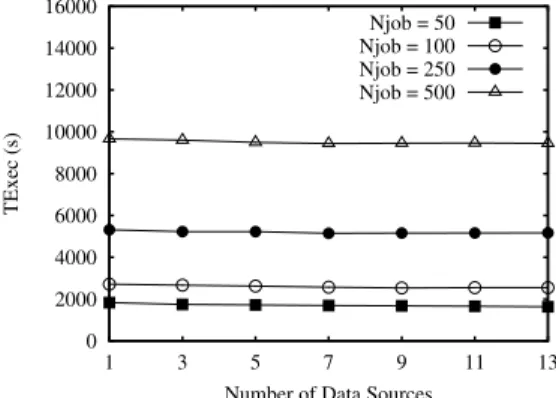
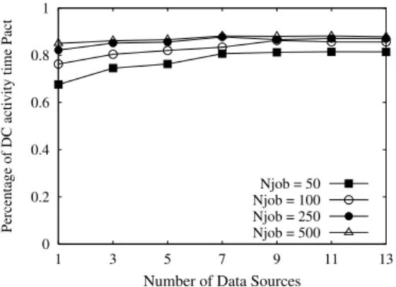
5.1 Base scenario . . . 82
5.2 Redundant submission of job scenario . . . 84
5.3 With data caching scenario . . . 88
5.4 Peers disconnection scenario . . . 92
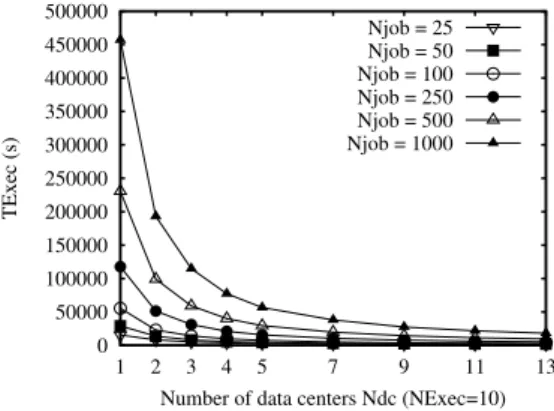
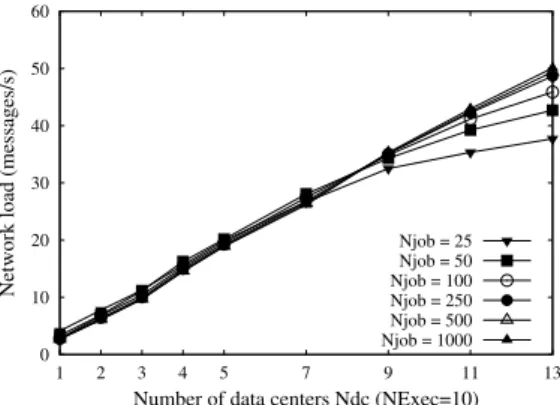
5.5 Scalability analysis . . . 101
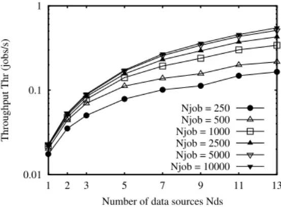
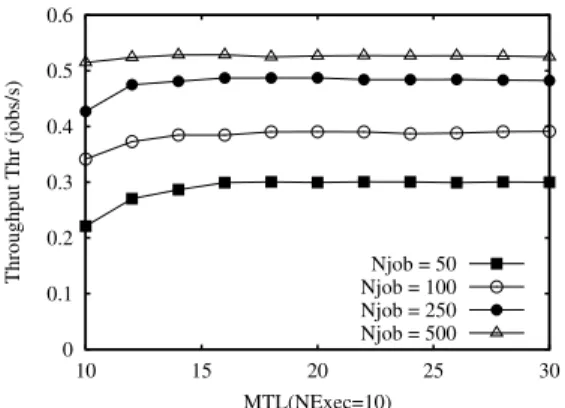
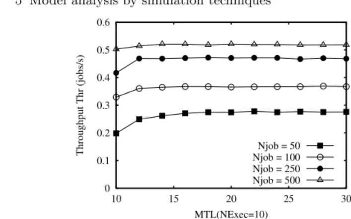
5.6 Multiple jobs assigner scenario . . . 106
6 P2P networks for music information retrieval . . . 109
6.1 DART scenario . . . 110
6.2 Distributed Simulations . . . 114
Part I
1
Distributed systems
Computer technology has revolutionized science. Scientists have developed accurate mathematical models of the physical universe, and computers pro-grammed with these models can approximate reality at many levels of scale: an atomic nucleus, a protein molecule, the Earth’s biosphere, or the entire universe. Using these programs, we can predict the future, validate or dis-prove theories, and operate ”virtual laboratories” that investigate chemical reactions without test tubes [56].
Computer technology also has revolutionized itself to better support scientific required tasks and thanks to the electronic innovation.
Since Internet diffusion many desktop computers, laptop, play stations and so on were linked to the network to share data and to intercommunicate, as side effect these computers constitute a huge virtual computer made by com-putation resource and data spread over all the network. Distributed systems is exactly the technology that incorporate this concept to use shared unused resources.
There are several definitions and view points on what distributed systems are. Coulouris defines a distributed system as ”a system in which hardware or software components located at networked computers communicate and coordinate their actions only by message passing” [1]; and Tanenbaum defines it as ”A collection of independent computers that appear to the users of the system as a single computer” [2]. Leslie Lamport once said that ”A distributed system is one on which I cannot get any work done because some machine I have never heard of has crashed” reflecting on the huge number of challenges faced by distributed system designers. Despite these challenges, the benefits of distributed systems and applications are many, making it worthwhile to pursue.
The main features of a distributed system include [1, 2]:
• Functional separation: It’s based on functionality/services provided, capa-bility and purpose of each entity in the system.
• Inherent distribution: Entities such as information, people, and systems are inherently distributed. For example, different information is created and maintained by different people. This information could be generated, stored, analysed and used by different systems or applications which may or may not be aware of the existence of the other entities in the system. • Reliability: Long term data preservation and backup (replication) at
dif-ferent locations is managed.
• Scalability: It consists in the addition of more resources to increase per-formance or availability. In the opposite in centralize systems scalability is usually restricted by the amount of centralized operation necessary and such system largely avoid central instances or servers.
• Economy: Resources are shared by many entities to help reduce the cost of ownership. As a consequence of these features, the various entities in a distributed system can operate concurrently and possibly autonomously. Tasks are carried out independently and actions are co-ordinated at well-defined stages by exchanging messages.
As a consequence of these features, the various entities in a distributed system can operate concurrently and possibly autonomously. Tasks are carried out independently and actions are co-ordinated at well-defined stages by exchang-ing messages. Also, entities are heterogenous, and failures are independent. Generally, there is no single process, or entity, that has the knowledge of the entire state of the system.
So far various types of distributed systems and applications have been developed and are being used extensively in the real world.
Inside of the various types of distributed systems, we analyze Clusters [3], Grids [5], and P 2P (Peer-to-Peer) networks [27].
1.1 Cluster computing
A cluster is a dedicated group of interconnected computers that appears as a single super-computer. It’s possible classify clusters depending from possible applications to do with. High availability clusters have a single virtual host on the network interface where a very big number of users can connect; an ex-ample is a website as a websearch engine accessed bye many people frequently or a huge database with a huge frequence of query access.
High reliability clusters are generally made bye to twins machine, one the mirror of the other, that are opportunaly configured then once one is not available the other starts work in sake of. Load condivision clusters are ar-ranged in a way that different kind of concurrent users can access available resources thanks the mediation of a Resource Manager. Load balance cluster are arranged in a way that a resource request can be forwarded to any avail-able node depending from the load, think for example about a cluster that
1.1 Cluster computing 5
must manage a growing number of users in an online game, a scientific data management and business applications. High performance cluster are special for process that generally can split in small subprocess and they are weakly dependent as in scientific engineering, robot management, medical imagines analysis, military control systems. Finally Cluster grid are clusters geograph-ically distributed in stand of being inside a room, we will refer to them with the name grid computing in the rest of this work.
Since they can support real time applications as well, cluster systems should solve temporal constraints well defined to acceding resources of one appli-cation. From software point of view they need operating systems ad hoc or conventional operating systems with a software support for communication and data sharing, also to perform their task they need again specific schedul-ing algorithms.
Realizing a cluster means to build a ”parallel computer”, you need N com-puting nodes (N > 1) linked by a communication network to allow the data exchange among these nodes. No special requirements about net topology, speed and if dedicated or not. About software, a cluster generally uses open-source programs. Beowulf project [4] is the referement design model for many cluster realized like this and in figure 1.1 there is an architectural schema of it.
Beowulf clusters are tipically of computing centers where the issue is high
Fig. 1.1.Beowulf: the schema
performance computing, cpu intensive and storage intensive.
Thanks opensource software and reusing available unused old computers were operating system linux works well, clusters can offer high reliablity and at the same time not high costs.
1.2 Grid computing
The older definition of what a grid is how it’s intended nowadays, it’s from Ian Foster and Carl Kessellman that, in 1999, defined computation grids in The Grid: Blueprint for a New Computing Infrastructure as ”A computational grid is a hardware and software infrastructure that provides dependable, con-sistent, pervasive and inexpensive access to high-end computational capabili-ties”. In this vision, the Grid will be to all computational resources what the World Wide Web presently is to documents containing information.
Grid users will have in fact at their disposal distributed high performance com-puters able to access and process terabytes of data stored in global databases, plus the appropriate tools to control and to share these resources.
In [17] Foster again try to define grids introducing the concept of virtual orga-nizations. In this work the grid concept appears as the coordinated resources sharing and problem solving in dynamic, multi-institutional virtual organi-zations (VO). With V O is intended a set of individuals and/or institutions defined by such sharing rules. Later Foster synthesize a grid by listing three
VO3
VO2 VO1 Resource Cluster1
Resource Cluster2
Fig. 1.2.Virtual Organizations accessing different and overlapping sets of resources
primary attributes [6]:
1. Computing resources are not administered centrally. 2. Open standards are used.
3. Non-trivial quality of service is achieved.
Plaszczak/Wellner define grid technology as ”the technology that enables re-source virtualization, on-demand provisioning, and service (rere-source) sharing between organizations”. IBM defines grid computing as ”the ability, using a set of open standards and protocols, to gain access to applications and data, processing power, storage capacity and a vast array of other computing re-sources over the Internet. A grid is a type of parallel and distributed system
1.2 Grid computing 7
that enables the sharing, selection, and aggregation of resources distributed across ’multiple’ administrative domains based on their (resources) availabil-ity, capacavailabil-ity, performance, cost and users’ quality-of-service requirements” [9]. Buyya defines a grid as ”a type of parallel and distributed system that en-ables the sharing, selection, and aggregation of geographically distributed au-tonomous resources dynamically at runtime depending on their availability, capability, performance, cost, and users’ quality-of-service requirements” [10] CERN, one of the largest users of grid technology, talk of The Grid: ”a service for sharing computer power and data storage capacity over the Internet” [11]. A grid can be also intended as a type distributed system that enables coor-dinated sharing and aggregation of distributed, autonomous, heterogeneous resources based on users’ QoS (Quality of Service) requirements.
Conceptually, the Grid can be thought of in terms of three layers. Underlying everything is the computational and data grid: the computer hardware and data networks upon which the work will be conducted. Above this is the ’in-formation grid’: the databases of in’in-formation to be accessed by the hardware, and systems for data manipulation. On top is the ’knowledge grid’, where high-level applications will mine the data for the knowledge that can form the basis of semantic understanding and intelligent decision making.
Middleware acts to interface between three types of entity: the users, the data they wish to process, and the computational resources required for this pro-cessing. Central to these interactions are metadata, that is to say descriptive information about these three types of entity, organized in a systematic man-ner that makes automated interactions possible.
Individual agents can continuously represent the users, the data and the re-sources on the Grid by presenting their metadata, while who offer a grid ser-vice must deal with authentication and authorization for manage payment, scheduling of activities, task monitoring.
A key point for successful Grid computing, is in fact to provide security access policies. When a single user account with a single log-on procedure must be sufficient for pervasive (any time, any place) access to all the computational resources required, with security permissions being handled automatically be-tween the separate systems in a manner transparent to the user. This requires the development of certification systems employing modern public key en-cryption technology to establish the identity and trustworthiness of the user (user authentication), and then to grant him/her access to those computa-tional facilities and databases that the user has the right to use, perhaps by virtue of institutional membership or subscription to a database service (user authorization).
For the Grid to become a reality, there is the strict requirement that the appli-cations used for information processing on both local and distant computers become integrated and truly interoperable. New software developments such as XML (eXtensible Markup Language), RDF (Resource Description Frame-work) and CORBA (Common Object Request Broker Architecture), together with systems for load balancing between distant computers, and task
integra-tion toolkits such as Globus [16], are likely to form the basis of the Grid tools that will be central to future interoperability, providing homogeneous access to heterogeneous data and resources [7].
So far grids are commonly used to support applications emerging in the ar-eas of e-Science and e-Business, which commonly involve geographically dis-tributed communities of people who engage in collaborative activities to solve large scale problems and require sharing of various resources such as comput-ers, data, applications and scientific instruments.
1.3 Grids vs. Clusters
At first look it can seems that Grids and clusters can solve the same kind of computations, in fact both may satisfy high-performance or high-throughput requirements by enabling distributed computing. The point is that grids solve the more complicated problem of providing computing resources to groups that span organizational boundaries, where resources are spread among the groups. In fact, a grid may marshal numerous clusters from different organi-zations into a logical set of computational resources available to a group of authorized users. By definition, grid services must live in more a complex en-vironment where resources must be shared and secured according to policies that may differ from organization to organization. In contrast, cluster comput-ing evolved simple as a way of solvcomput-ing computationally demandcomput-ing problems by using large numbers of commodity CPUs together with commodity net-working technology.
Over the last part of the 20th century as computing power increased and prices dropped, it became clear that if large numbers of low-cost computers, for example computer connected to Internet, could provide supercomputing power at a much lower cost than purpose-built, high-performance supercom-puters.
Because processes must communicate with other processes via the net-work, rather than hardware on the motherboard, communication is much slower. Also, high-speed RAM availability is limited by the amount of mem-ory available to hosts in the cluster. Given these constraints, clusters have still proven invaluable in high-performance computing for solving problems that can easily be broken into many smaller tasks and distributed to workers. Ideal problems require little communication between workers, and their work product can be combined or processed in some way after the tasks have been completed.
Grids can certainly solve these sorts of problems, but they might have a su-percomputer available for tasks that cannot be broken up so easily. The grid would provide a way to match this supercomputer with your problem, re-serve it, authenticate your task and authorize its use of the supercomputer. It
1.4 P2P systems 9
Fig. 1.3.Columbia Super Cluster of NASA from 10.240 processors
would execute the task and provide a way to monitor progress on that super-computer. When the supercomputer completes your task, it would send the results to you. This supercomputer might even be in a different hemisphere and owned by a different institution. Finally, the grid might even debit your account for using this service.
By way of contrast, a cluster might provide some of these services. It might even be a cluster of supercomputers, but the cluster would probably belong entirely to your institution, and it probably wouldn’t bill you. In addition, your institution probably would have a consistent policy and method of au-thenticating your credentials and authorizing your use of the cluster. More im-portant, the cluster would probably exercise complete and centralized control over its resources [12]. Finally we must considerate that Grids emerged to solve resource-sharing problems across academic and research institutions, where funding for researching a broad topic might be distributed across a variety of institutions that employed researchers focusing on particular aspects of that topic. Sharing this experimental data among many geographically distributed research organizations and researchers requires sophisticated resource-sharing technology that can expose those resources in an open, standard, and secure way. These requirements far exceed those of a cluster intended to provide high-performance computing for a given institution.
1.4 P2P systems
The P 2P idea is based on the notion of increasing the decentralization of systems, applications, or simply algorithms. It is based on the principles that the world will be connected and widely distributed and that it will not be possible or desirable to leverage everything off of centralized, administratively managed infrastructures. P 2P is a way to leverage vast amounts of computing power, storage, and connectivity from personal computers distributed around
the world.
A P 2P system then is one in which autonomous peers depend on other au-tonomous peers. Peers are auau-tonomous when they are not wholly controlled by each other or by the same authority, e.g., the same user. Peers depend on each other for getting information, computing resources, forwarding requests, etc. which are essential for the functioning of the system as a whole and for the benefit of all peers. As a result of the autonomy of peers, they cannot necessarily trust each other and rely completely on the behaviour of other peers, so issues of scale and redundancy become much more important than in traditional centralized or distributed systems.
As with any computing system, the goal of P 2P systems is to support appli-cations that satisfy the needs of users.
Centralized systems that serve many clients typically bear the majority of the cost of the system. When that main cost becomes too large, a P 2P architecture can help spread the cost over all the peers. Much of the cost sharing is realized by the utilization and aggregation of otherwise unused re-sources which results both in net marginal cost reductions and a lower cost for the most costly system component, then P 2P model brings a cost shar-ing/reduction.
Either such system can give an improved scalability/reliability respect the situation to have a strong central authority thanks autonomous peers.
A decentralized approach lends itself naturally to resource aggregation and interoperability. Each node in the P 2P system brings with it certain resources such as compute power or storage space. Applications that benefit from huge amounts of these resources, such as compute-intensive simulations or dis-tributed file systems, naturally lean toward a P 2P structure to aggregate these resources to solve the larger problem.
In many cases, users of a distributed system are unwilling to rely on any centralized service provider. Instead, they prefer that all data and work on their behalf be performed locally. P 2P systems support this level of autonomy simply because they require that the local node do work on behalf of its user. Related to autonomy is the notion of anonymity and privacy. A user may not want anyone or any service provider to know about his or her involvement in the system. With a central server, it is difficult to ensure anonymity because the server will typically be able to identify the client, at least by Internet address. By employing a P 2P structure in which activities are performed locally, users can avoid having to provide any information about themselves to anyone else. P 2P systems assume that the computing environment is highly dynamic. That is, resources, such as compute nodes, will be entering and leaving the system continuously. When an application is intended to support a highly dynamic environment, the P 2P approach is a natural fit. P 2P system even is linked to dynamism concept, that is enabling ad-hoc communication and collaboration, where members come and go based perhaps on their current physical location or their current interests.
1.5 Grid vs. P2P 11
1.5 Grid vs. P2P
Generally moderate-sized communities use Grid services specially when it’s mandatory a trusted information exchange. In contrast, current P 2P systems deal with many more participants and offer limited and specialized services, have been less concerned with qualities of service and trust. Anyway the point is that both two environments deal with the same general problem, namely, resource sharing within VOs that may not overlap with any existing organiza-tion.
Grid systems integrate resources that are more powerful, more diverse, and better connected than the typical P 2P resource. Anyway the two types of system have both conceptual and concrete distinction about resources defini-tion, target communities, connectivity, scalability, reliability and so on. A Grid resource in fact might be a cluster, storage system, database, or sci-entific Instrument of considerable value that is administered in an organized fashion according to some well defined policy, while home computers arguably represent the majority of P 2P resources.
P2P has been popularized by file sharing and public resource computing ap-plications, the latter is a high performance conputing based on volunteers who donate their personal computers’ unused resources to a computationally intensive research project.
In contrast with Grids, public resource computing involves an asymmetric relationship between projects and participants. Projects are typically small academic research groups with limited computer expertise and manpower. Most participants are individuals who own Windows, Macintosh and Linux PCs, connected to the Internet by telephone or cable modems or DSL, and often behind network-address translators (NATs) or firewalls. The computers are connected intermittently to the network, remaining available for a limited time with reduced reliability. Anyway the number of nodes connected in a P2P network at a given time is much greater than in a grid. Thus, partici-pants are not computer experts, and participate in a project only if they are interested in it and receive ”incentives” such as credit and screensaver graph-ics. Projects have no control over participants, and cannot prevent malicious behaviour [72, 19].
Grids generally include powerful machines that are statically connected through high performance networks with high levels of availability. On the other hand, the number of accessible nodes is generally low because access to grid resources is bounded to rigorous accounting mechanisms.
About applications, P 2P systems tend to be vertically integrated solutions to specialized resource-sharing problems: currently deployed systems share ei-ther compute cycles or files while Grid systems more data intensive. For ex-ample, a recent analysis of Sloan Digital Sky Survey SDSS data [15] involved, on average, 660 MB input data per CPU hour; In contrast, SETI@home [67] moves at least four orders of magnitude less data: a mere 21.25 KB data per
CPU hour. The reason is presumably, in part at least, better network con-nectivity, which also allows for more flexibility in Grid application design: in addition to loosely coupled Applications, Grids have been used, for example, for numerical simulation and branch-and-bound based optimization problems. Grid systems must address the problem of scalability and deal with failures
Fig. 1.4.The constellation Auriga, picture for Mapping the Universe project [15]
in terms of amount of activity, while P 2P in terms of participating entities. Early Grid implementations did not address scalability and self-management as priorities. Thus, while the design of core Grid protocols does not preclude scalability, actual deployments often employ centralized components. One ex-ample of that is the Globus toolkit [16] where you can find central repositories for shared data, centralized resource management components, and centralized and/or hierarchical information directories. This situation is changing, with much work proceeding on such topics as reliable and scalable management of large job pools, distributed scheduling, replica location, and discovery.
Far larger P 2P communities exist: millions of simultaneous nodes in the case of file-sharing systems and several million total nodes in SETI@home. The amount of activity is also significant, albeit, surprisingly, not always larger than in the relatively smaller-scale Grids (1-2 TB per day in file sharing sys-tems). This large scale has emerged from robust self-management of large numbers of nodes.
The technologies used to develop Grid and P 2P applications differ both in the specific services provided and in the emphasis placed on persistent, multipurpose infrastructure. Grid provide to creating and operating persis-tent, multipurpose infrastructure services for authentication, authorization, discovery, resource access, data movement, and so forth.
1.5 Grid vs. P2P 13
Many Grid communities use the open source Globus Toolkit [16] as a tech-nology base. Significant effort has been channeled toward the standardization of protocols and interfaces to enable interoperability between different Grid deployments. P 2P systems have tended to focus on the integration of simple resources (individual computers) via protocols designed to provide specific vertically integrated functionality. Such protocols do, of course, define an in-frastructure, but in general the persistence properties of such infrastructures are not specifically engineered but are rather emergent properties [18].
2
Peer-to-Peer
2.1 Historical
Peer-to-Peer (P 2P ) is the model of earlier distributed applications and it aims to employ distributed resources to perform function in a decentralized man-ner; in P 2P applications, resource can be computing, storage and bandwidth, while function can be computing, data sharing, collaboration.
E-mail systems built on the SimpleMail Transfer Protocol (SMTP) and Usenet News are first examples of such applications. The main idea is that there are local servers that received a message then they built connections with peer (P) servers to deliver messages into a user’s mail file or into a spool file containing messages for the newsgroup. The File Transfer Protocol (FTP) currently is a client-server application, in the beginning it was very common for individu-als to run FTP servers on their workstations to provide files to their Ps for such reason it’s can be intended as the precursor to today’s file sharing P 2P systems. Even an indexing system named Archie, was developed to provide a central search mechanism for files on FTP servers. This structure with cen-tral search and distributed files is exactly replicated in a very popular P 2P system: Napster.
At the time decentralized dial-up networks as UUNet and Fidonet were used, they were composed of a collection of machines that made periodic dial-up connections to one another. On a typical connection, messages (again, typically e-mail or discussion group entries) were transferred bi-directionally. Often, a message would be routed through multiple dial-up hops to reach its destination. This multi-hop message routing approach can be seen in current P2P systems such as Gnutella.
At the very beginning of Internet all the content was provided by ma-chines at similar levels (ignoring routing intermediaries that provide services like DNS and DHCP) with Arpanet. If someone wanted to publish something, they published it on their machine (or one within their physical location).
Things were balanced because equal amounts of traffic flowed both directions - all the nodes were P s. An historical example of P 2P application was the Internet Relay Chat (IRC). The origin of IRC can be traced back to the Department of Information Processing Science at the University of Oulu1
, Finland during the latter part of August 1988. IRC consists of distributed servers that relay chat information between each other. A set of these servers is called a net. A user, or client, connects to one of these servers and joins a channel (like a chat room). Once they are in a channel their chat is relayed to every other client in that channel on that net. There are hundreds of es-tablished nets available and a given net can have thousands of channels. Gradually with time at the late-80’s and early- 90’s more transients users connected to the network. This moved to more of a server model, with multi-ple clients connecting to it. It also allowed the use of less expensive and less functional computers such as desktop PCs. Today again with faster always on connections a new type of connectivity between the individual clients is on the rise.
The first wide use of P 2P seems to have been in instant messaging systems such as AOL Instant Messenger. These are typically hybrid P 2P solutions with discovery and brokering handled by a central server followed by direct communication between the P messaging systems on the PCs. The current phase of interest and activity in P 2P was driven by the introduction of Nap-ster [NapNap-ster 2001] in 1999. It came at a time when computers and their network connections were nearing the level found previously in technical and academic environments, and re-created earlier approaches with an interface more suitable to a non-technical audience.
2.2 P2P networks: comparing to client-server model
Network configurations mainly include server and P networks. Typically in server (or Client / Server) networks there are one or more central servers that choreograph all networking activity between all the machines, and thanks to technologies like DHCP assign network address to them, then technologies like DNS allow one client to connect to the other using a common name without needing to know the machines actual address. In the opposite in a P network all the machines are equal, with each machine discovering what other machines are on the network and obtaining an address without the help of a server. The presence of servers aims to provide a central location allowing the entire network to be administered from one location (or at least that is the theory.) and it symbolizes a source that can spread contents by request.
The downside is that server and administrator do the extra work to make it easier on the clients and end users. Servers, representing the single point of
1
2.3 P2P protocol definitions 17
failure of the whole network, are costly, both in time and money, so the more computers to be serviced by a server, the more cost effective it is to have one.
Fig. 2.1.Communication Systems: (a)Client-Server, (b)Peer-to-Peer
A P network does not require a special central server; this makes it more appealing to small networks, especially ones found in the home.
The downside is that it can take a while for a machine to find another machine on the network, and the burden of connecting correctly and P 2P obtaining an address is placed on each client. If a P network is going to be very large then an administrator may be required to keep things running smoothly, unfor-tunately there is no central server for them to administer, so they will be required to administer each machine on the network.
A P can be seen as a client, where client indicates subservient to a server. Instead of calling the model client to client we call it peer to peer since for these connections they are equal or P s.
The P s may have to handle a limited connectivity, support possibly indepen-dent naming, and be able to share the role of the server.
The fact that a central server may have made the initial connection to the Internet (or some other network) possible is irrelevant in where the final ac-tivity takes place. The outcome is that all the action is in the P s, or the fringes of the network as having all entities being client and servers for the same purpose.
If you want to publish something, you do so on your own machine, instead of on an external server. P 2P is a new abstraction on top of the current Internet structures.
2.3 P2P protocol definitions
To explain what P 2P protocol aims to do, it’s suitable starting from common definitions of it. P 2P is defined by online dictionaries in the following ways: ”P 2P is a communications model in which each party has the same capabilities
and either party can initiate a communication session” by Whatis.com, ”A type of network in which each workstation has equivalent capabilities and responsibilities” by Webopedia.com, ”A P 2P computer network refers to any network that does not have fixed clients and servers, but a number of P nodes that function as both clients and servers to other nodes on the network” by Wikipedia.org.
Either there are several of the definitions of P 2P that are being used by the P 2P community. The Intel P 2P working group defines it as ”the shar-ing of computer resources and services by direct exchange between systems” [25]. Alex Weytsel of Aberdeen defines P 2P as ”the use of devices on the internet periphery in a nonclient capacity” [21]. P 2P are a ”Class of systems and applications that employ distributed resources to perform a function in a decentralized manner” according to Vana Kalogeraki, Riverside. Ross Lee Gra-ham defines P 2P through three key requirements: a) they have an operational computer of server quality; b) they have an addressing system independent of DNS; and c) they are able to cope with variable connectivity [29]. Clay Shirky of O’Reilly and Associate uses the following definition: ”P 2P is a class of applications that takes advantage of resources - storage, cycles, content, human presence - available at the edges of the Internet. Because accessing these decentralized resources means operating in an environment of unstable connectivity and unpredictable IP addresses, P 2P nodes must operate outside the DNS system and have significant or total autonomy from central servers” [26]. Finally, Tim Kindberg of HP Labs defines P 2P systems as those with independent lifetimes [22].
2.4 P2P architectures
Decentralization is one of the major concept of P 2P systems. This includes distributed storage, processing, information sharing and also control informa-tion. Based on the degree of decentralization in a P 2P system, we can classify them into two categories: Purely Decentralized and Hybrid Architecture. Re-cently a new architecture has been successfully proposed: the Super Peer (SP) model [83], for details look at last section in this chapter.
Purely Decentralized seems to be the best but at the same time the hardest to realize, it can’t rely on a always on servers, the case of Hybrid Architecture, or on a P with extra features, the case of SP .
An architecture overview is depicted in the following figure:
Following a description of each architecture according the way P node are linked and how they intercommunicate.
As well a valuation is done respect of main distributed application char-acteristic: management extendibility scalability, security, fault-tolerance and load balancing.
2.4 P2P architectures 19
Fig. 2.2. Architecture
A pure P 2P system is a distributed system without any centralized con-trol. In such systems all nodes are equivalent in functionality. In such networks the nodes are named as servent (SERver+cliENT), the term servent repre-sents the capability of the nodes of a peer-to-peer network of acting at the same time as server as well as a client.
Pure P 2P systems are inherently scalable, they are inherently fault-tolerant too, since there is no central point of failure and the loss of a P or even a number of Ps can easily be compensated. They also have a greater degree of autonomous control over their data and resources. On the other hand such systems present slow information discovery infact a query of the network must make many hops to reach many nodes, which takes much longer and there is no guarantee about quality of services. If the network is very large then you will most likely never query the entire network. Also because of the lack of a global view at the system level, it is difficult to predict the system behaviour.
Gnutella [39], Freenet [41], Chord [44] and CAN [46] are instances of such purely decentralized systems.
Hybrid or Brokered P 2P systems make use of a Central Server or Bro-ker that maintains directories of information about registered users to the network, in the form of meta-data. This server may provide other services to aid in the matching of the Ps. Once the match is made then the end-to-end interaction is directly between two P clients.
Each node only ever knows about the central server and any other nodes that the central server introduces it too. The advantage of brokered in fact is that it has the performance of centralized but also allows direct P connec-tions. Later in this section is detailed how the indexing phase happen in such systems, it can be centralized or decentralized as well.
Fig. 2.3.Brokered architecture
2.5 Discovery mechanisms for P2P systems
Distributed P 2P systems often require a discovery mechanism to locate spe-cific data within the system. In general P 2P systems have evolved from first generation centralized structures to second generation flooding-based and then third generation systems based on distributed hash tables (chord, can). First taxonomy of search methods can be done according to the location of the metadata , if centralized or decentralized, in informed approaches.
2.5.1 Centralized and decentralized indexes
Centralized indexes and repositories is the mechanism used in hybrid P 2P systems.
Centralized indexing scenario is the case of a central server maintains an index with meta data (file name, time of creation etc.) of files that are currently being shared by active P s, a table of registered user connection information (IP addresses, connection speeds etc.), a table listing the files that each user holds and shares in the network. Each P maintains a connection to the central server, which store all information regarding location and usage of resources. Upon request from a P , the central index will match the request with the best P in its directory that matches the request. The best P could be the one that is cheapest, fastest, nearest, or most available, depending on the user needs. Then the data exchange will occur directly between the two P s.
The user then opens a direct connection with the P that holds the re-quested file, and downloads it. This architecture is used by Napster [51].
The disadvantage is that such systems are vulnerable to censorship and malicious attack. Because of central servers they have a single point of failure. They are not inherently scalable, because of limitations on the size of the
2.5 Discovery mechanisms for P2P systems 21
Fig. 2.4.Centralized indexing
database and its capacity to respond to queries. As central directories are not always updated, they have to be refreshed periodically.
To deals with this problems the decentralized indexing model comes up, in this case the central server task is to register the users to the system and fa-cilitates the P discovery process. The server doesn’t represent the single point
Fig. 2.5.Distributed indexing
of failure in fact some of the nodes assume a more important role than and they are called ”supernodes” [55]. These nodes maintain the central indexes for the information shared by local P s connected to them and proxy search requests on behalf of these P s so queries are therefore sent to SuperNodes, not to other Ps, this happens in Kazaa [49, 37] and Morpheus [52].
To be designed as SP , a P must have sufficient bandwidth and process-ing power and a central server provides new P s with a list of one or more SuperNodes with which they can connect. Such node turns into regular P if it doesn’t receives at least the required number of connections to client nodes within a specified time, then it tries to become a SuperPeer again for another probation period. The concept of Super Nodes is common in Gnutella [38].
Respect to purely decentralized systems, decentralized indexing hybrid architectures reduce the discovery time and also they reduce the traffic on
messages exchanging between nodes. Respect to centralized indexing, they reduce the workload on central server but they present slower information discovery.
2.5.2 Discovery techniques in unstructured P2P systems
Discovery techniques in unstructured P 2P systems, according to the informa-tion they utilize to locate objects, include Blind methods, the case of Gnutella, Random Walks, and Informed methods, the case of Napster, Routing Indices. Pure P 2P model belong to unstructured P 2P systems, this is the case in which each P does not maintain any central directory and each P publishes information about the shared contents in the P 2P network. Since no single P knows about all resources, P s in need for resources flood an overlay network queries to discover a resource, each request from a P is flooded (broadcasted) to directly connected P s, which themselves flood their P s etc., until the re-quest is answered or a maximum number of flooding steps occur. Flooding based search networks are built in an ad hoc manner, without restricting a priori which nodes can connect or what types of information they can ex-change [31]. Different broadcast policies have been implemented to improve search in P 2P networks [36, 34, 35].
Flooding broadcast of queries algorithms include simple flooding, iterative deepening, Random walk, Informed search. The base flooding algorithm is the Simple Flooding; according this algorithm a P sends the query to all of its neighbour nodes, in the case a neighbour has the result, it will notify the query initiator; and the query initiator can get the result directly from it. In the case the neighbour hasn’t the result this will decrease TTL (Time To Live) and forward the query to its neighbours. The forward of this query halts when TTL becomes 0. It means that a query initiator can get redundant results, coming from different nodes having the resource asking for, or no result even if data exists in network.
The simple flooding generates a lot of network traffic, to deal with this, in the Iterative Deepening the idea is that the search is started using flooding with small TTL. In this way, in the case the result is close to the requiring P , the message doesn’t congest all the network.
If no result is found, new search is started with larger TTL. Then the algorithm halts when result is found or limit of TTL is reached. To allow this a policy array indicating for each search iteration the TTL, must be used. Otherwise the TTL can change according a choosed math function. An other flooding algorithm example is the Unstructured: Random Walk (Blind Search). In this case the query initiator selects only one neighbor to send the query accord-ing some heuristics. For example, if a neighbor always returns satisfactory results, it might be selected more often. This is possible if it receives feedback of whether neighbor was able to provide result, if the neighbor doesn’t have the result, it will select one of its neighbors based on the heuristics. This
pro-2.5 Discovery mechanisms for P2P systems 23
Fig. 2.6.Flooding algorithm: (a)Resource discovery in Napster, (b) Flooding-based broadcast
cess will repeat until result is found or TTL is met.
The opposite of the Blind Search is the Informed Search approach, according this in fact each P has a lookup index, neither complete nor accurate, storing file locations which have been searched previously.
If a P finds the location for a file in the index, it will directly contact the file holder and get the file. otherwise, it uses flooding for search. Once the file is found, the reverse path of query path is used to inform the query initiator about the location, it’s this the way so P s on the query path can update their indices speeding up next queries.
A Informed Search variation is that instead of storing the the file location the file will be replicated along the reversed query path. This combined with lookup indices is called Replication Search algorithm.
All the mechanisms analyzed so far, typicall of unstructured P 2P systems have some drawbacks as a the large amount of messages travelling inside the network, the need of duplicate queries and the hard task to opportunely set the TTl value, keeping under consideration that a too high TTL value brings a high load in network, a too low value could bring to not found any result.
Search in structured P 2P systems: the routing model The routing model adds structure to the way information about resources are stored using distributed hash tables and in some special case content based hash table. This protocol provide a mapping between the resource identifier and location, in the form of a distributed routing table, so that queries can be efficiently routed to the node with the desired resource.
Data items are distributed over P s according to a well defined algorithm. P s choose their data items using additional replication mechanism to check for availability. Each node has a unique identifier (Hash of IP) and each data item (e.g. file) that must be assigned has a key (Hash of title, author etc). Each node is responsible for storing files that have a key that is similar to the node identifier: given a key, a node efficiently routes the query to the node with an ID closet to the key.
This protocol reduces the number of P 2P hops that must be taken to locate a resource. The look-up service is implemented by organizing the P s in a structured overlay network, and routing a message through the overlay to the responsible P [23]. Starting from infomation stored in a DHT many services can be implemented as File sharing, Archiving, Database, names Di-rectory, cat services, publish/subscribe systems, distributed Cache, streaming audio/video systems. Example of Structured P 2P systems that implement Distributed Hash Table DHT are Chord [MIT], Pastry [Microsoft Research UK, Rice University], Tapestry [UC Berkeley], Content Addressable Network (CAN) [UC Berkeley], SkipNet [Microsoft Research US, University of Wash-ington], Kademlia [New York University], Viceroy [Israele, UC Berkeley], P-Grid [EPFL Ginevra].
An alternative of hash table structure is the bloom filter. A Bloom fil-ter is an ingenious randomized data-structure for concisely representing a set in order to support approximate membership queries. The space efficiency is achieved at the cost of a small probability of false positives. It was invented by Burton Bloom in 1970 for the purpose of spell checking and for many years it was widely mentioned in a variety of large-scale network applications such as shared web caches, query routing, and replica location. For more details about refers to [77].
Search algorithms analyzed so far are classified inside the following com-parison table 2.7.
2.6 Uses
P2P networks enable applications such as file-sharing, instant messaging, on-line multiuser gaming and content distribution over public networks. Dis-tributed storage systems such as NFS (Network File System) provide users
2.6 Uses 25
Fig. 2.7.Search in P 2P comparison
with a unified view of data stored on different file systems and computers which may be on the same or different networks. The domains of P 2P appli-cations can be subdivided into four categories, particularly distributed com-puting, file sharing, collaboration, platforms, as summarized in figure 2.8 [27].
Fig. 2.8.Taxonomy of P 2P systems and applications
2.6.1 Distributed Computing
These applications use resources from a number of networked computers. The general idea behind these applications is that idle cycles from any computer
connected to the network can be used for solving the problems of the other computers that require extra computation. Some distributed computing appli-cations are chat systems (like ICQ, IRC, Jabber, etc.) and PRC appliappli-cations, see at next chapter.
2.6.2 File sharing
Content storage and exchange is one of the areas where P 2P technology has been most successful. File sharing applications [30, 32, 33] focus on storing information on and retrieving information from various P s in the network. Distributed storage systems based on P 2P technologies are taking advantage of the existing infrastructure to offer the following features [27]:
• File exchange areas: some file sharing systems, such as Freenet, Gnutella, and Kazaa provide the user with a potentially unlimited storage area by taking advantage of redundancy. A given file is stored on some nodes in the P2P community, but it is made available to any of the P s. A P requesting a given file just has to know a reference to a file, and is able to retrieve the file from the community by submitting the file reference.
• Highly available safe storage The duplication and redundancy policies in some projects, as in Chord, offer virtual storage places where critical files get replicated multiple times, which helps ensuring their availability. • Manageability: P 2P systems, as Freenet, enable easy and fast retrieval of
the data by distributing the data to caches located at the edges of the network. The location of the data is not known by the retriever, perhaps not even after the data is retrieved.
2.6.3 File sharing: P2P example architectures
One of the best-known example of P 2P systems is Napster, it became famous as a music exchange system. Other instances are Gnutella, Freenet, Kazaa, Chord, etc.. P 2P systems, using a discovery mechanism based on hash tables, are Chord, CAN and Pastry too. Following each system short description.
Napster
Napster was originally developed to defeat the copying problem and to enable the sharing of music files over the Internet. Napster is a Brokered system, Although search mechanism is centralized, the file sharing mechanism is de-centralized. Everyone connected to the central Napster server (may it rest in peace) and told the server what files it had available and how other P s could reach it. Then when a node is looking for a specific file or P it asks the central server which responds with a listing of files and/or server connec-tion informaconnec-tion. At that point the two P s connect to each other to transfer the file. Napster uses the centralized directory model to maintain a list of
2.6 Uses 27
Fig. 2.9.Napster architecture
music files, where the files are added and removed as individual users con-nect and disconcon-nect from the system. Users submit search requests based on keywords such as ”title,” ”artist,”etc., the actual transfer of files is done di-rectly between the P s. Napster’s centralized directory model inevitably yields scalability limitations and loss in performance.
Gnutella
Gnutella [38] was introduced in March of 2000, by two employees of AOL’s Nullsoft division. It is an opensource file sharing program with functionality similar to that of Napster. Gnutella originally was an Equal P Decentralized architecture. Any new node could connect to any existing P in the network and then have access to the network. Once connected to a P it then had access to every P connected to that P , which continues out in a ripple effect until the TTL expires. Such decentralized nature of Gnutella provides a level of anonymity for users, but also introduces a degree of uncertainty.
With time Gnutella evolved to the SP Decentralized architecture. This helped answer the issues of scalability and slow search speeds. With this system a new node connects to one or more SP s and once connected has access to all P s (and SP s) connected to that SP , continuing out in a ripple patter until the TTL expires. For a user to connect to a Gnutella network they only need to know the address of one other machine on the network. Once that connection is made then that node will discover other nodes on the network until a few connections are made. The Gnutella discovery Protocol include four types of messages:
• Pong: reply to a Ping message. It contains the IP and port of the respond-ing host and number and size of files shared.
• Query: a search request. It contains a search string and the minimum speed requirements of the responding host.
• Query hits: reply to a Query message. It contains the IP and port and speed of the responding host, the number of matching files found and their indexed result set.
Fig. 2.10.Gnutella Protocol
After joining the Gnutella network(by using hosts such as gnutellahosts.com), a node sends out a Ping message to any node it is connected to. The nodes send back a Pong message identifying themselves, and also propagate the ping to their neighbours. Gnutella originally uses TTL-limited flooding (or broad-cast) to distribute Ping and Query messages. At each hop the value of the field TTL is decremented, and when it reaches zero the message is dropped. In order to avoid loops, the nodes use the unique message identifiers to detect and drop duplicate messages.
This approach improves efficiency and preserve network band width. Once a node receives a QueryHit message, indicating that the target file has been
2.6 Uses 29
identified at a certain node, it initiates a direct out-of-network download, es-tablishing a direct connection between the source and target node. Although the flooding protocol might give optimal results in a network with a small to average number of P s, it does not scale well. Furthermore, accurate dis-covery of P s is not guaranteed in flooding mechanisms. Also TTL effectively segments the Gnutella network into subsets, imposing on each user a virtual horizon beyond which their messages cannot reach. If on the other hand the TTL is removed, the network would be swamped with requests. One more problem is that the Gnutella protocol itself does not provide a fault tolerance mechanism. The hope is that enough nodes will be connected to the network at a given time such that a query will propagate far enough to find a result.
Freenet
The Freenet system [40, 41] was conceptualized by Ian Clarke in 1999 while at the University of Edinburgh and its implementation began in early 2000. The primary mission of Freenet is to make use of the system anonymous that means provide storage and use the system without being possible identify who determined who placed a file into the system and who made a request. The idea is that FreeNet is creating a network where individuals can post their opinion without the fear of their identity being revealed. And once their opinion is posted, it will remain available as long as people are downloading it. In Communication architecture Freenet is similar to Gnutella in commu-nication architecture, it’s a completely decentralized system and it represents the purest form of P 2P system. One optimization is that each time a file is requested a copy is made on the nodes closer to the requesting node. This makes it more convenient the next time it is requested from the same loca-tion, in fact Freenet is considered responsive as possible. In this system each P from the network is assigned a random ID and each P also Every node in the Freenet network maintains a set of files locally up to the maximum disk space allocated by the node operator. When all disk space is consumed, files are replaced in accordance with a least recently used (LRU) replacement strat-egy. Freenet’s basic unit of storage is a file. Each file shared on such system, is identified by an ID. These are typically generated using the hash SHA-1 Function [43]. Each P will then route the document towards the P with the ID that is most similar to the document ID. This process is repeated until the nearest P ID is the current P0sID. Each routing operation also ensures that a local copy of the document is kept. When a P requests the document from the P 2P system, the request will go to the P with the ID most similar to the document ID. This process is repeated until a copy of the document is found. Then the document is transferred back to the request originator, while each P participating the routing will keep a local copy.
Fig. 2.11.Freenet: searching for data
The scalability of Freenet has been studied by its authors using extensive simulation studies [42]. Their studies support the hypothetical notion that route lengths grow logarithmically with the number of users.
Chord
Chord [44] uses a decentralized P 2P lookup protocol that stores key/value pairs for distributed data items. Given a key, it maps key a node responsible for storing the key’s value. In the steady state, in an N-node network, each node maintains routing information about O(logN ) other nodes, and resolves all lookups via O(logN ) messages to other nodes. Updates to the routing information for nodes leaving and joining require only O(log2
N) messages.
CAN: Content Addressable Networks
CAN [46] is a mesh of N nodes in virtual d-dimensional dynamically parti-tioned coordinate space. Each P keeps track of its neighbours in each dimen-sion. When a new P joins the network, it randomly chooses a point in the identifier space and contacts the P currently responsible for that point. The contacted P splits the entire space for which it is responsible into two pieces and transfers responsibility of half to the new P , the new P also contacts all of the neighbours to update their routing entities. The CAN discovery mech-anism consists of two core operations namely, a local hash-based look-up of a pointer to a resource, and routing the look-up request to the pointer. The CAN algorithm guarantees deterministic discovery of an existing resource in O(N1d) steps.
2.6 Uses 31
Pastry
An approach similar to Cord was also used in Pastry [45]. In the Pastry each node network has a unique identifier (nodeId) from a 128-bit circular index space. The pastry node routes a message to the node with a nodeId that is numerically closest to the key contained in the message, from its routing table of O(logN), where N is the number of active Pastry nodes. The expected of routing steps is O(logN). Pastry takes into account network locality; it seeks to minimizes the distance messages travel, according to a scalar proximity metric like the number of IP routing hops.
Kazaa (FastTrack)
Kazaa [49] is a Hybrid system that uses SuperNodes as local search hubs for lookup. Each SP role reminds to the role of the central server in Napster, ex-cept that here it is limited to a small part of the network. SP are nodes chosen inside the network because better in elaboration power, bandwidth, average time being connected on the net, respect others. Kazaa uses an intelligent download system to improve download speed and reliability. Each user send its files list to a SP node then SP s periodically send lists each others. The ad-vantage is that when there is a file request, the system automatically finds and downloads files from the fastest connections, failed transfers are automatically resumed, and files are even downloaded from several sources simultaneously to speed up the download. When files are imported, the system automatically extracts meta-data from the contents of the files (such as ID3 tags for mp3 files). This makes for much faster andmore accurate searches.Kazaa also uses a technique called MD5 hashing to make sure the contents of multi-sourced files are identical.
WASTE
WASTE [50] is a mesh-based workgroup tool that allows for RSA encrypted communication between small groups workgroups of users. The network is actually a partial mesh, with every possible connection made, limited by fire-walls and routers. Communication is then routed over the network along the route of lowest latency, which allows communication between firewalled P s via a non firewalled P .
2.6.4 Collaboration
Intuitively Collaboration is a new way to intend communication. If you wish chat with your friends over the network you shouldn’t need to subscribe to a central server. The regulation of members, content and connections has to be determined by the members, instead of a service provider. Whenever you want start a project with a few friends, sharing project files, discussion boards, white boards, chat sessions and other necessities inside a collaborative envi-ronment, you should have the chance to communicate directly. Collaborative P2P applications then aim to allow application level collaboration between users.
Fig. 2.13.Gaim: a client for instant messaging
Collaborative applications are generally event-based. P s form a group and begin a given task. The group may include only two P s collaborating directly, or may be a larger group. When a change occurs at one P (e.g., that P initi-ates sending a new chat message), an event is generated and sent to the rest of the group. At the application layer, each P’s interface is updated accordingly. There are a number of technical challenges that make implementation of this type of system difficult. Like other classes of P 2P systems, location of other P sis a challenge for collaborative systems. Many systems rely on centralized
2.6 Uses 33
directories that list all P s who are online, refers to figure 2.14. To form a new group, P s consult the directory and select the P s they wish to involve.
Fig. 2.14.Buddy list
Other systems, like Microsoft’s NetMeeting, can require that P s identify one another by IP address. This is much too restrictive, especially in environ-ments where groups are large.
Fault tolerance is another challenge. In shared applications, messages of-ten must be delivered reliably to ensure that all P s have the same view of the information. In some cases, message ordering may be important. While many well-known group communication techniques address these challenges in a non-P 2P environment, most P 2P applications do not require such strict guarantees. The primary solution employed in P 2P applications is to queue messages that have been sent and not delivered (i.e., because a given P is down or offline). The messages can then be delivered to the offline P when it comes back online. Realtime constraints are perhaps the most challenging aspect of collaborative implementations. Users are the ultimate end points in a collab-orative environment. As such, any delay can be immediately perceived by the user. Unfortunately, the bottleneck in this case is not the P 2P technology, but the underlying network. While many collaborative applications may work well in a local- area systems, wide-area latencies limit P 2P applications just as they limit client-server applications. Generally applications range from instant messaging and chat, to on line games, to shared applications that can be used in business, educational, and home environments. The gaming environment is
the one in which real time is the a constraint; The game DOOM is a so-called First Person Shooter (FPS) game in which multiple players can collaborate or compete in a virtual environment. DOOM uses a P 2P structure in which each player’s machine sends updates of the state of the environment (such as the player’s movement) to each of the other machines. Only when all updates have been received does the game update the view. This was marginally viable in local-area, small-scale games, but did not scale to wide-area games. Long latencies and uneven computing power at the various players machines made this lock-step architecture unusable. All FPS games since DOOM have used amore standard client-server architecture for communication. Jabber [47] is a set of streaming XML protocols and technologies that enable any two en-tities on the Internet to exchange messages, presence, and other structured information in close to real time. Groove [48] provides a variety of applica-tions for communication, content sharing (files, images and contact data), and collaboration (i.e. group calendaring, collaborative editing and drawing, and collaborative Web browsing).
2.6.5 Platforms
In terms of development, platforms such as JXTA [73], XtremWeb [74], Mi-crosoft’s .NET My Services and BOINC provide an infrastructure to support P2P applications. For example JXTA(TM) is based on Java technology and it is a set of open protocols that enable any connected device on the net-work, ranging from cell phones and wireless PDAs to PCs and servers, to communicate and collaborate in a P 2P manner. JXTA P s create a virtual network where any P can interact with other P s and resources directly, even when some of the P s and resources are behind firewalls and network address translations (NATs) or on different networks. A detailed description about the platform BOINC is given in next chapter.
2.7 Bittorrent
BitTorrent is a P 2P application that was invented because to facilitate fast downloads of popular files from the Internet in opposite then centralized down-load systems as in figure 2.15.
Thanks BitTorrent mechanism, each client can allow other clients to down-load from it, data that it had already downdown-loaded. Clients are available to share their just downloaded files because they are foster to do that (+upload = +download !) and in such way the free-riding is discouraged.
To understand how BitTorrent works, we describe the scenario of how it op-erates when a single file is downloaded by many users. Typically the number of simultaneous downloaders for popular files could be of the order of a few hundreds while the total number of downloaders during the lifetime of a file could be of the order of several tens or sometimes even hundreds of thousands.
2.7 Bittorrent 35
Fig. 2.15.Centralized download (a) vs. BitTorrent mechanism (b)
The basic idea in BitTorrent is to divide a single large file (typically a few 100 MBytes long) into pieces of size 256 KB each. For each file there is a cor-responding description file, with .torrent extension, with segments number, segments hash code and the server Tracker address. The Tracker is a central-ized software that store all active P s on a file, since the set of P s attempting to download the file do so by connecting to several other P s simultaneously and download different pieces of the file from different P s. Clients report infor-mation to the tracker periodically and in exchange receive inforinfor-mation about other clients that they can connect to. The tracker is not directly involved in the data transfer and does not have a copy of the file.
In a BitTorrent network, a P that wants to download a file first connects
Fig. 2.16.BitTorrent segment files flow
to the tracker of the file. The tracker then returns a random list of P s that have the file. The downloader then establishes a connection to these other P s and finds out what pieces reside in each of the other P s. A downloader then requests pieces which it does not have from all the P s to which it is