Introduction 1 Chapter I – Membrane processes
1.1 Introduction 5
1.2 Synthetic membranes and methods of preparation 7 1.3 Membranes with Symmetric and Asymmetric Structure 14
1.4 General terminology and definitions 16
1.5 Fluxes and driving forces in membrane separation processe 19
1.6 Membrane and module configuration 20
1.7 Membrane operations 27
References 39
Chapter II – General properties of citrus fruits
2.1 Introduction 42
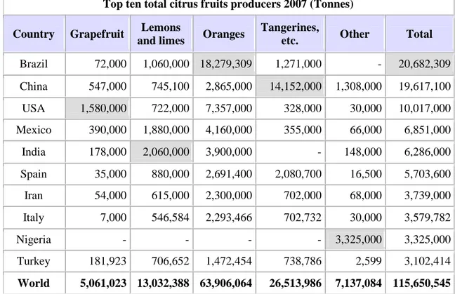
2.2 World production 43
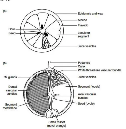
2.3 Anatomorphology of citrus fruit 49
2.4 Prevention potential of Citrus 50
2.5 Citrus biocompounds 54
References 61
Chapter III – Clarification of blood orange juice
3.1 Introduction 64
3.2 Material and methods 66
3.3 Results and discussion 72
References 80
Chapter IV – Osmotic distillation of clarified blood orange juice
4.1 Introduction 83
4.2 Materials and methods 84
4.3 Results and discussion 87
References 94
Chapter V - Analysis of anti-inflammatory activity of blood orange juice treated by membrane operations
5.1 Introduction 96
5.2 Materials and methods 99
5.3 Results and discussion 101
References 107
Fruits and vegetables play an important role in human nutrition. They are vital sources of essential minerals, vitamins, and dietary fiber, and supply complex carbohydrates, and proteins. They are good sources of calcium, phosphorus, iron, and magnesium and contribute over 90% of dietary vitamin C. Green and yellow fruits and vegetables are a rich source of vitamin A (b-carotene). Thiamine, niacin, and folic acid, which are required for normal functioning of the human body, are also present in significant quantities.
Recent developments in agriculture have contributed significantly to improved production of fruits throughout the world. Storage practices have been developed for each kind of fruit. Improvedpackageshave been developedthat protect thefruitand addimpact on the healthof the consumer.Foods characterised by protective and health-promoting potential, in addition to their nutritive value, are recognised as functional foods. The beneficial components in functional foods have been called by various terms such as phytochemicals, functional components and bioactive compounds.
Citrus fruits rank first in the world with respect to production among fruits. They are grown commercially in more than 50 countries around the world. In additionto oranges, mandarins, limes, lemons, pummelos, and grapefruits, other citrusfruits such as kumquats, Calamondins, citrons, Natsudaidais, Hassakus, andmany other hybrids are also commercially important. Citrus fruit production recorded a handsome increase during the 1990s, andrecently reached more than 150 million tons. Considering the therapeutic value of thesefruits and the general health awareness among the public, citrus fruit are gainingimportance worldwide, and fresh fruit consumption is likely to increase.Postharvest biology and technology has evolved into a branch of sciencethat combines biology and engineering. It has evolved rapidly over the pastfour or five decades, although scattered research efforts in various aspects ofthis field have been made previously all over the world. Increased citrus productioncombined with concern about growing population accelerated researchand stimulated the development of new technologies in basic and applied areas.
Epidemiological studies have consistently demonstrated that there is a clear significant positive association between the intake of fruit and vegetables and the reduced rate of
heart disease mortality, common cancers and other degenerative diseases as well as ageing. The protection that fruit and vegetables provide against these diseases has been attributed to various bioactive compounds.
In particular, most of the antioxidant capacity of fruit and vegetables can be attributed to polyphenolic compounds (such as flavonols, flavanols, anthocyanins and phenylpropanoids), other than vitamin C, vitamin E and β-carotene, which act as antioxidants or as agents of other mechanisms contributing to anticarcinogenic or cardioprotective action.
Citrus fruits are rich in flavonoids compounds, which have anticancer properties. Citrus fruit flavonoids have been shown to inhibit the growth of cancer cells and prevent the spread of tumors. Citrus flavonoids are also antioxidants that can neutralize free radicals and may protect against heart disease. Furtherthey may improve blood flow through coronary arteries, reduce the ability of arteries to form blood clots and prevent the oxidation of LDL (“bad”) cholesterol, which is an initial step in the formation of artery plaques.
In addition to being rich sources of flavonoids, citrus fruits are high in vitamin C, and are good sources of folate and potassium. Vitamin C is a powerful antioxidant and protects the body from damaging free radicals. It is also required for the synthesis of collagen, which helps wounds heal and helps hold blood vessels, tendons, ligaments and bone together.
Conserving the peculiarity of fresh fruit as well as colour, aroma, nutritional value and structural characteristics as much as possible, the food industry has focused on the development of processed items with increased shelf-life.On the other hand, during the industrial transformation, a large part of the characteristics determining the quality of the fresh product undergoes a remarkable modification: the thermal damage and the chemical oxidation degrade the most sensitive components reducing the quality of fresh fruits.
In order to solve these problems and to better preserve the properties of fresh fruits, several new “mild” technological processes have been proposed in the last years.
Within the agro-food industry, membrane technologies can work as well or better than the existing technology regarding product quality, energy consumption and environmental issues. The use of membrane separation, clarification, purification and
concentration processes represents one of the most powerful tools for the agro-food industry to introduce innovative processes in order to pursue targets such as process intensification and reduction of production costs. In addition, membrane operations represent a valid alternative to thermal evaporation processes which cause the deterioration of heat sensitive compounds leading to a remarkable qualitative decline of the final product. On the other hand, current filtration of a wide variety of juices is performed by using fining agents such as gelatine, diatomaceous earth, bentonite and silica sol which cause problems of environmental impact due to their disposal.
Juice clarification, stabilisation, depectinization and concentration are typical steps where membrane processes such as microfiltration (MF), ultrafiltration (UF), nanofiltration (NF) and osmotic distillation (OD) have been successfully used and are today very efficient systems to preserve the nutritional and organoleptic properties of the fresh product owing to the possibility of operating at room temperature with low energy consumption and without chemical additives.
The aim of this work was to study the effect of an integrated membrane process in the separation, recovery and concentration of bioactive compounds in the blood orange juice.
In the first Chapter, a general introduction on membrane science and technologies, including their advantages over traditional separation processes, is reported. A description of the chemical composition of Citrus fruits and their bioactive compounds which are of interest for nutriaceuticalapplications, is reported in Chapter II. The clarification of the blood orange juice and the effect of an UF membrane on the recovery of phenolic compounds from the depectinised blood orange juice are analysed and discussed in Chapter III. The concentration of the clarified juice by OD and the performance of the OD process in terms of productivity and quality of the concentrated juice are analysed in Chapter IV. Finally, Chapter V discusses the results obtained in the evaluation of the anti-inflammatory activity of clarified and concentrated juices produced through an integrated membrane process UF/OD.
The recovered fractions from the blood orange juice through the investigated membrane processes represent an ideal substrate for the formulation of new products with improved characteristics for food, pharmaceutical and nutriaceutical applications.
These studies offer also interesting perspectives for the recovery and reuse of bioactive compounds from other citrus fruits and from by-products of the industrial transformation of fruit and vegetables.
M
EMBRANE
P
ROCESSES
1.1Introduction
The term membrane most commonly refers to a thin, film-like structure that separates two fluids. It acts as a selective barrier, allowing some particles or chemicals to pass through, but not others. In some cases, especially in anatomy, membrane may refer to a thin film that is primarily a separating structure rather than a selective barrier.
The concept of a membrane has been known since the eighteenth century, but it remained as only a tool for physical / chemical theories development until the end of World War II, when drinking water supplies in Europe were compromised and membrane filters were used to test for water safety. However, due to the lack of reliability, slow operation, reduced selectivity and elevated costs, membranes were not widely exploited. Microfiltration (MF) and ultra-filtration (UF) represent the membranes first used on the large scale. Since the 1980’s, these separation processes, along with electrodialysis, are employed in large plants and, today, a number of experienced companies serve the market. A membrane is a layer of material which serves as a selective barrier between two phases and remains impermeable to specific particles, molecules, or substances when exposed to the action of a driving force. Some components are allowed passage by the membrane into a permeate stream, whereas others are retained by it and accumulate in the retentate stream [1].
Membrane engineering has already provided interesting solutions to some of the major problems of our modern industrialized society. Membrane processes meet the requirements of process intensification because they have the potential to replace conventional energy-intensive techniques, to accomplish the selective and efficient transport of specific components, and to improve the performance of reactive processes. Membrane techniques are essential to a wide range of applications including the production of potable water, energy generation, tissue repair, pharmaceutical
production, food packaging and the separations needed for the manufacture of chemicals, electronics and a range of other products [2].
Membrane processes are today consolidated systems in various productive sectors for their capacity to operate at room temperature and with low energetic consumption [3]. Membrane science and technology has led to significant innovation in both processes and products over the last few decades, offering interesting opportunities in the design, rationalization, and optimization of innovative productions [4]. At the heart of every membrane process there is an interface clearly materialized by a nano-structured/functionalized thin barrier. It controls the exchange between two phases not only by external forces and under the effect of fluid properties, but also through the intrinsic characteristics of the membrane material itself [5]. The separation, concentration and purification of molecular mixtures are major problems in the chemical industries. Membrane processing is a technique that permits separation, purification, clarification and concentration without the use of heat. Particles are separated on the basis of their molecular size and shape with the use of pressure and specially designed semi-permeable membranes.
Membrane technology has already gained a huge importance in the last two decades and now is competing with other separation technologies in terms of energy efficiency, high separation capacity, selective separation and capital investments. In many areas of applications, the conventional separation processes have been replaced with the ones based on membranes. In water desalination, for example, conventional thermal based processes have been replaced with RO due to their less energy intensive nature combined with small foot print and safer operations [6].
Membrane filtration can be a very efficient and economical way of separating components that are suspended or dissolved in a liquid. Among the various types of membranes, composite membranes commonly consist of a porous support layer with a thin dense layer on top that forms the actual membrane [7].
Efficient separation processes are needed to obtain high-grade products in the food and pharmaceutical industries to supply communities and industry with high quality water and to remove or recover toxic or valuable components from industrial effluents. For this task a multitude of separation techniques such as distillation, precipitation, crystallization, extraction, adsorption, and ion-exchange are used today. More recently,
these conventional separation methods have been supplemented with a family of processes based on the use of semi-permeable membranes as separation barriers.
Membranes and membrane processes were first introduced as an analytical tool in chemical and biomedical laboratories; they developed very rapidly into industrial products and methods with significant technical and commercial impact. The basic properties of membrane operations make them ideal for industrial production: they are generally athermal and do not involve phase changes or chemical additives; they are simple in concept and operation, modular and easy to scale-up; furthermore, they are characterized by a low energy consumption permitting a rational utilization of raw materials and recovery and reuse of by-products. The membranes used in various applications differ widely in their structure, in their function and in the way they are operated. However, all membranes have several features in common that make them particularly attractive tools for the separation of molecular mixtures [8].
1.2Synthetic membranes and methods of preparation Synthetic membranes are fabricated in two main geometries:
1. Flat sheet—utilized in the construction of flat sheet, disc, spirally wound, plate, and frame modules.
2. Cylindrical—utilized in tubular and capillary, or hollow fiber modules.
Membranes can be prepared from both ceramic and polymeric materials. Ceramic materials have several advantages over polymeric materials, such as higher chemical and thermal stability. However, the market share of polymeric membranes is far greater than ceramic membranes as the polymeric materials are easier to process and less expensive. A handful of technical polymers are currently used as membrane materials for 95% of all practical applications [9]. Polymeric materials that are used to prepare separation membranes are mostly organic compounds. A number of different techniques are available to prepare synthetic membranes. In Table 1.2-1, a schematic representation of different materials used for preparation of membranes has been given.
Table 1.2-1 Schematic representation of different membrane materials MF Microfiltration UF Ultrafiltration NF Nanofiltration RO Reverse osmosis GS Gas separation PV Pervaporation MD Membrane distillation
Although synthetic membranes show a large variety in their physical structure and chemical nature, they can conveniently be classified in five basic groups:
(1) microporous media; (2) homogeneous solid films; (3) asymmetric structures; (4) electrically charged barriers; (5) liquid films with selective carriers.
This classification, however, is rather arbitrary and there are many structures which would fit more than one of the abovementioned classes, e.g., a membrane maybe
microporous, asymmetric in structure, and carry electrical charges. Any other classification of synthetic membranes, e.g., according to their application or methods of preparation, would serve the same purpose of phenomenologically categorizing the various types of synthetic membranes [10].
• Neutral microporous membranes
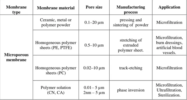
Neutral, microporous films represent a very simple form of a membrane which closely resembles the conventional fiber filter as far as the mode of separation and the mass transport are concerned. These membranes consist of a solid matrix with defined holes or pores which have diameters ranging from less than 2 nm to more than 20 µm. Separation of the various chemical components is achieved strictly by a sieving mechanism with the pore diameters and the particle sizes being the determining parameters. Microporous membranes can be made from various materials, such as ceramics, graphite, metal or metal oxides, and various polymers. Their structure may be symmetric, i.e., the pore diameters do not vary over the membrane cross section, or they can be asymmetrically structured, i.e., the pore diameters increase from one side of the membrane to the other by a factor of 10 to 1,000. The properties and areas of application of various microporous filters are summarized in Table 1.2-2.
Table 1.2-2 Microporus membranes: preparation and application
Membrane type
Membrane material Pore size Manufacturing process Application Microporous membrane Ceramic, metal or polymer powder 0.1–20 µm pressing and
sintering of powder Microfiltration
Homogeneous polymer
sheets (PE, PTFE) 0.5–10 µm
stretching of extruded polymer sheet. Microfiltration, burn dressings, artificial blood vessels. Homogeneous polymer sheets (PC) 0.02–10 µm track-etching Microfiltration Polymer solution (CN, CA) 0.01– 5 µm 2nm – 5 µ m phase inversion Microfiltration, Ultrafiltration, Sterilization.
• Symmetric microporous sintered membranes
Sintered membranes are the simplest in their function and in the way they are prepared. The structure of a typical sintered membrane is shown in the scanning electron micrograph of Figure 1.2-1. This photograph shows a PTFE microporous membrane made by pressing a fine powder into a film or plate of 100 to 500 µm thickness and then sintering the film at a temperature which is just below the melting point of the polymer. This process yields a microporous structure of relatively low porosity, in the range of 10 to 40% and a rather irregular pore structure with a very wide pore size distribution.
Figure 1.2-1SEM of a microporous sintered membrane prepared from a PTFE powder.
Sintered membranes are made on a fairly large scale from ceramic materials, glass, graphite and metal powders such as stainless steel and tungsten. The particle size of the powder is the main parameter determining the pore sizes of the final membrane, which can be made in the form of discs, candles, or fine-bore tubes. Sintered membranes are used for the filtration of colloidal solutions and suspensions. This type of membrane is also marginally suitable for gas separation. It is widely used today for the separation of radioactive isotopes, especially uranium.
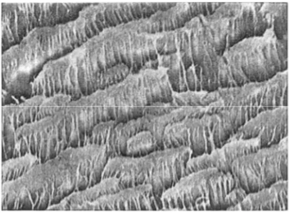
• Stretched membranes
A relatively simple procedure for preparing microporous membranes is the stretching of a homogeneous polymer film of partial crystallinity. This technique is mainly employed with films of polyethylene or PTFE which have been extruded from a polymer powder and then stretched perpendicular to the direction of extrusion [11, 12]. This leads to a partial fracture of the film and relatively uniform pores with diameters of 1 to 20 µm. A
typical stretched membrane prepared from PTFE is shown in the scanning electron micrograph of Figure 1.2-2.
Figure 1.2-2SEM of a microporous membrane prepared by stretching an extruded PTFE film perpendicular to the direction of extrusion.
These membranes, which have a very high porosity, up to 90%, and a fairly regular pore size are now widely used for microfiltration of acid and caustic solutions, organic solvents, and hot gases. They have to a large extent replaced the sintered materials used earlier in this application.
Stretched membranes can be produced as flat sheets as well as tubes and capillaries. The stretched membrane made out of PTFE is frequently used as a water repellent textile for clothing, such as parkas, tents, sleeping bags, etc. This membrane type has, because of its very high porosity, a high permeability for gases and vapors, but, because of the hydrophobic nature of the basic polymer, is up to a certain hydrostatic pressure completely impermeable to aqueous solutions. Thus, the membrane is repellent to rain water but permits the water vapor from the body to permeate. More recently, this membrane has also been used for a novel process, generally referred to as membrane distillation, i.e., to remove ethanol from fermentation broths or wine and beer to produce low alcohol products and for desalination of seawater. These membranes are also used for desalination of saline solutions and in medical applications such as burn dressings and artificial blood vessels [10].
• Capillary pore membranes
These membranes are made in a two step process. During the first step, a homogeneous 10 to 15 µm thick polymer film is exposed to collimated, charged particles in a nuclear
reactor. As particles pass through the film, they leave sensitized tracks where the chemical bonds in the polymer backbone are broken. In the second step, the irradiated film is placed in an etching bath. In this bath, the damaged material along the tracks is preferentially etched forming uniform cylindrical pores. The pore density of a track-etched membrane is determined by the residence time in the irradiator, while the pore diameter is controlled by the residence time in the etching bath. The minimum port diameter of these membranes is approximately 0.01 µm. The maximum pore size that can be achieved in track etched membranes is determined by the etching procedure. The polymer will not only be dissolved along the sensitized track left by the penetrating particle but also on both surfaces of the film. Thus, with exposure time in the etching medium the pore sizes increase and the thickness of the film is correspondingly reduced. The scanning electron micrograph in Figure 1.2-3 shows a typical track etched polycarbonate membrane.
Capillary pore membranes are prepared today mainly from polycarbonate and polyester films. The advantage of these polymers is that they are commercially available in very uniform films of 10 to15 µm thickness which is the maximum penetration depth of collimated particles obtained from a nuclear reactor which have an energy about 0.8 to 1 MeV. Particles with higher energy, up to 10 MeV, may be obtained in an accelerator. They are used today to irradiate thicker polymer films, up to 50 µm thickness, or inorganic materials such as mica [13].
On an industrial scale, capillary pore membranes are used for the production of ultrapure water for the electronic industry. Here, they show certain advantages over other membrane products because of their short "rinse down" time and good long-term flux stability.
Because of their surface filter characteristics, particles retained by the membranes can be further monitored by optical or scanning electron microscopy. Figure1.2-4 shows a scanning electron micrograph of asbestos fibers accumulated on a capillary pore membrane in an air pollution control application.
Figure 1.2-4 SEM of asbestos filter accumulated on the surface of a capillary pore membrane.
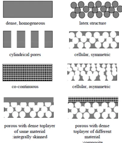
Depending on the application, different membrane morphologies will be used. In Figure 1.2-5 a schematic representation of different morphologies is given.
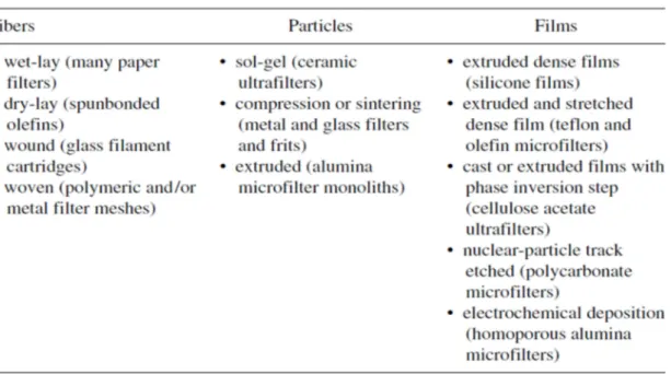
The formation techniques of membranes and filters are shown in the Table 1.2-3.
Table 1.2-3Formation techniques of membranes and filters
1.3 Membranes with Symmetric and Asymmetric Structure
1.3.1 Symmetric structure
Although most of the practically useful membranes are asymmetric, as explained later, some of the membranes have symmetric structures. They are prepared in the following ways:
• Track etching - A sheet of polymeric film moves underneath a radiation
source and is irradiated by high-energy particles. The spots that are subjected to bombardment of the particles are degraded or chemically altered during this process. Then, the film undergoes an etching process in an alkaline or hydrogen peroxide bath (depending on the material), where the polymer is etched along the path of high-energy particles.
• Precipitation from the vapor phase - A cast polymer solution that
consists of polymer and solvent is brought into a nonsolvent vapor environment saturated with solvent vapor. The saturated solvent vapor suppresses the evaporation of solvent from the film; the nonsolvent molecules diffuse into the film causing polymer coagulation.
A schematic representation of the a symmetric structure is depicted in Figure 1.3-1. (A)
(B)
Figure 1.3-1 Schematic representation of symmetric structure.(a)Silicon Membranes; (b)Aluminum membranes morphologies
1.3.2 Aymmetric structure
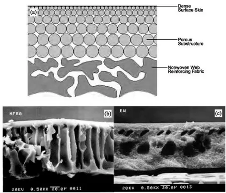
Most membranes used in industries have an asymmetric structure. Figure 1.3-2 shows schematically a typical cross-sectional view of an asymmetric membrane. It consists of two layers: the top one is a very thin dense layer (also called the top skin layer), and the bottom one is a porous sub layer. The top dense layer governs the performance (permeation properties) of the membrane; the porous sub layer only provides mechanical strength to the membrane. The membranes of symmetric structures do not possess a top dense layer. In the asymmetric membrane, when the material of the top layer and porous sub layer are the same, the membrane is called ’’integrally skinned asymmetric membrane’’. On the other hand, if the polymer of the top skin layer is different from the polymer of the porous sub layer, the membrane is called ’’composite membrane’’. The advantage of the composite membrane over the integrally skinned asymmetric membrane is that the material for the top skin layer and the porous sub layer can be chosen separately to optimize the overall performance [9].
Figure 1.3-2 Schematic representation of asymmetric structure. Cross-section illustration of (a) an integrally skinned asymmetric membrane, plus SEM cross sections
of dense-skinned (b) polyacrylonitrile and (c) polysulfone membranes manufactured by GE-Osmonics Inc.
1.4 General terminology and definitions
Membrane filtration technology has developed a specialized terminology.
The definitions themselves provide a basis for discussing the equipment and operating principles.
• Batch filtration: A fixed volume of feed material is filtered and the retentate(the
feed material not filtered) is recycled (or not removed) until a specific recovery of permeate is obtained. Thus the composition of the feed is continuously changing with time.
• Cake: The cake is whatever is left sitting on the membrane or filter’s surface (or
whatever builds up continuously during the filtration).
• Concentration Polarization: Accumulation of rejected solute on the feed side of
Interrupting or stopping the filtration process allows the concentration polarization to dissipate.
• Conductance: The reciprocal of resistance. The flux of solvent(or solutes)
through a membrane is often empirically described as being proportional to the product of a driving force and a conductance. Several layers with different thicknesses and specific conductances (conductance normalized by its thickness) may be combined to completely describe the membrane system under a variety of conditions.
• Crossflow (tangential flow) filtration: The main flow direction is
across(tangential to) the membrane or filter surface. This operating mode will typically have a retentate.
• Dead-end filtration: The main flow direction is perpendicular to the membrane
or filter’s surface. This operating mode may or may not have a retentate.
• Feed (or sample): The initial solution presented to the membrane or filter is
called the feed. It can be a mixture of solvent, solutes, and particulates.
• Fluid velocity (crossflow velocity): The average velocity in the feed channel in a
flowing system or the average radial velocity across the membrane or filter’s surface in a stirred system.
• Flux: The mass or volumetric flow through the filter/membrane per unit time per
unit area.
• Fouling: Irreversible decline in flux due to adsorption, deposition, or other
accumulation on the surface and/or in the pores of the membrane or filter. This can be caused by any combination of solutes, particulates, and precipitates.
• Hydraulic pressure drop: In a flowing system this is mechanical pressure
required to move the feed through the device to become the retentate. It is mechanical energy required in addition to the average trans-membrane pressure (TMP). The viscosity of the feed solution and shape of the feed channel (including any inserts to increase mixing) will affect this energy requirement.
• MWCO (molecular weight cut-off): The molecular mass of dissolved molecules
for which a rejection of at least 90% will be observed based on the measurement technique and assumptions used by the manufacturer. A standard measurement technique does not exist.
• Particulates: These are species that are suspended in the primary solvent or
continuous phase. Particulates can include colloids, cells (and cell fragments), viruses, spores, inorganic precipitates, dust, etc.
• Permeability: The permeance normalized for the thickness of the membrane or
filter’s separating layer.
• Permeate (filtrate, product): Permeate refers to whatever passes through the
membrane.
• Pore size: The diameter of the largest pore based on the measurement technique
and assumptions used by the manufacturer. A standard measurement technique does not exist.
• Permeance (pressure-normalized flux): The flux divided by the TMP.
• Permselective: A membrane is permselective towards a feed mixture if the
concentrations in the permeate differ from the feed.
• Recovery: Percentage of the feed that permeates a single filtration stage. A stage
may be an element, device, or module in which there is no interruption in the contact of the feed solution and the membrane or filter.
• Rejection: A measure of the fraction of solute or particulate retained by the
membrane or filter. Several rejection quantities (e.g., true, observed, and average rejection, and sieving coefficient) are defined and used.
• Retentate (concentrate, reject): Retentate is the fluid feed material that does not
pass through the membrane or filter.
• Solutes: These are species that are dissolved in the primary solvent or
continuous phase. Solutes can include salts and both small and large molecules of a variety of types.
• Transmembrane pressure (TMP): The difference in absolute pressure across the
thickness of the membrane or filter is called the transmembrane pressure. Depending upon the type of filtration operation this can change with position along the surface of the filter. Also it can result from a variety of sources, such as inert gas blanket, pumping, and centrifugal force [14].
1.5 Fluxes and driving forces in membrane separation processes
Separations in membrane processes are the result of differences in the transport rates of chemical species through the membrane interphase. The transport rate is determined by the driving force or forces acting on the individual components and their mobility and concentration within the interphase. The mobility is primarily determined by the solute’s molecular size and the physical structure of the interphase material, while the concentration of the solute in the interphase is determined by chemical compatibility of the solute and the interphase material, the solute’s size, and the membrane structure. The mobility and concentration of the solute within the interphase determine how large a flux is produced by a given driving force. In membrane separation processes there are three basic forms of mass transport. The simplest form is the so-called passive
transport. Here, the membrane acts as a physical barrier through which all components
are transported under the driving force of a gradient in their electrochemical potential. Gradients in the electrochemical potential of a component in the membrane interphase may be caused by differences in the hydrostatic pressure, the concentration, the temperature, or the electrical potential between the two phases separated by the membrane. The second form of mass transport through the membrane interphase is the so-called facilitated transport. Here, the driving force for the transport of the various components is again the gradient in their electrochemical potential across the membrane. The different components, however, are coupled to a specific carrier in the membrane phase. Facilitated transport, therefore, is a special form of the passive transport. Completely different, however, is the third form of mass transport through membranes. It is generally referred to as active transport. Here, various components may be transported against the gradient of their electrochemical potential. The driving force for the transport is provided by a chemical reaction within the membrane phase. Active transport is coupled with a carrier in the membrane interphase and is found mainly in the membranes of living cells [15]. It has, to date, no significance in synthetic membranes.The transport of mass in a membrane is a non equilibrium process and is conventionally described by phenomenological equations such as Fick’s law which relates the fluxes of matter to the corresponding driving forces [16]:
i i i d C
J D
d z = −
J = flux for species i
Di= Diffusion coefficient for species i
i
dC
dz =Concentration gradient
Membrane systems, available in variety of separation capabilities have been introduced for their peculiarities in different fields. The removal of turbidity, precursors and disinfectant tolerant micro-organisms relating to both groundwater and surface water supplies, as well as tapping into new water supplies, such as brackish and seawater are some interesting applications [17]. The following table shows the membrane separation processes relative to contaminant size.
1.6 Membrane and module configuration
The practical equipment where the actual membrane based separation occurs is known as membrane module. The basic aim of development of membrane modules is to provide maximum membrane area in relatively smaller volume, so that the permeate flux i.e., the productivity of the system is maximum. These membrane modules are of five types: (i) plate and frame module, (ii) spiral wound, (iii) hollow fiber ,(iv) capillary and (v) tubular.
1.6.1 Membrane configuration
There are three different configurations in terms of the shape of membrane as shown below as shown in Figure 1.6.1-1[18].
Flat sheet Hollow fiber Tubular
Different materials can be realized for pressure driven process like microfiltration (i.e., PVDF-MFB, MBR-200), ultrafiltration ( Polyacrylonitrile: 50, 200, PAN-350, PAN-400, PAN-400C/D, PAN-450; Polysulfone: PS-10, PS-20, PS-30, PS-35; Polyethersulfone: PES-2, PES-5, PES-10, PES-20, PES-900C/D; Poly(vinylidene fluoride): PVDF-4, PVDF-350, PVDF-400, PVDF-400B, PVDF-400R, PVDF-400HE, PVDF-400HB, PVDF-400HA), nanofiltration (NF-2A, NF-3A, NF-6) and reverse osmosis.
Packed in extreme high density, hollow fibres can range from smaller than a strand of human hair to bristles several hundred microns in diameter. Hollow fibre devices are used in both UF and RO applications. Fibres are produced by extrusion through annular dies. Thousands of strands are tightly bundled and bonded at the end into potting. The bundles are usually housed in PVC or stainless steel. When applied in a suitable application, hollow fibre membranes are more economical and cost effective than conventional separation methods.
When used properly, hollow fibre devices can function for years without replacement. These devices can be operated at high pressure, allowing them to desalt highly concentrated seawater. In special applications, they can be operated as high as 138 bar. Hollow fibre is a flexible membrane; it can carry out the filtration by either "inside-out" or "outside-in". Hollow fiber membranes have been successfully employed in industrial water, industrial wastewater, and beverage processing applications worldwide, and are particularly well suited to the high production demands of municipal drinking water and wastewater treatment plants. Regardless of flow pattern, hollow fiber membranes offer a compact, cost-effective solution for filtering large volumes of liquids utilizing minimal space and energy. Cross flow hollow fibre membrane also reduces fouling as the fluid flows from the inside of the hollow fibre and pass through to the outside of the membrane. Despite the size of the hollow fibre membrane being smaller than other types of membrane, its circular structure allows a higher surface area which in turn, yields a higher performance.
Tubular membranes can easily process solutions containing high suspended solids, and concentrate products proficiently and repeatedly to high end-point concentration levels without plugging, making them ideal for recovering wastewaters, and clarifying juices. Tubes can be used individually or grouped together in a package. Membranes are placed
inside a support porous tube, and these tubes are placed together in a cylindrical shell to form the unit module. Tubular devices are primarily used in MF and UF applications because of their ability to handle process streams with high solids and high viscosity properties, as well as for their relative ease of cleaning. Membrane area per unit volume is small and fouling is mainly eliminated by mechanical cleaning [19].
Tubular membranes have high durability due to their rugged construction and are extremely foulant-resistant. In cross-flow mode, the rugged large-diameter tubes allow for high velocity in the tubes even with very dirty process fluids. This maintains maximum “sweeping” action at the membrane surface and minimizes foulant build-up and clogging, even with high suspended solids [18].
1.6.2 Module configuration
The Plate and frame (PF) configuration has been developed for relatively small scale applications that deal with high membrane fouling potential. The module structure is complex to seal the spaces among the membrane plates and pressure loss across the module is high due to the zigzag flow. Today, PF is primarily used for electrodialysis, leachate filtration, etc.
The heart of plate-frame module is the support plate that is sandwiched between two flat sheet membranes. The membranes are sealed to the plate, either gaskets with locking devices, glue or directly bonded. The plate is internally porous and provides a flow channel for the permeate which is collected from a tube on the side of the plate.
Ribs or grooves on the face of the plate provide a feed side flow channel. The feed channel can be a clear path with channel heights from 0.3 to 0.75 mm. The higher channel heights are necessary for high viscosity feeds; reduction in power consumption of 20 to 40% can be achieved by using a 0.6 mm channel compared to a 0.3 mm channel. Alternatively, retentate separator screens (20 or 50 mesh polypropelyne) can be used. Commercial plate-frame units are usually horizontal with the membrane plates mounted vertically. They can be run with each plate in parallel plates in two or three series. Laboratory units are also available as preformed stacks up to 10 plates. A typical plate and frame module is shown in Figure 1.6.2-1.
Figure 1.6.2-1 Schematic representation of:(a)plate and frame module; (b)flow diagram.
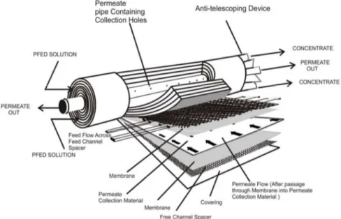
The Spiral Wound (SW)configuration was developed in 1970's to make plate and frame
modules more compact for the feed with low fouling potential. It provides large specific surface area at relatively low costs. Feed water flows through feed channel parallel to the axis. The permeate travels permeate channel to be collected in the center pipe as shown in the figure Figure1.6.2-2. This module configuration is most commonly used with the membranes with tight pore sizes such as UF, NF, and RO.
In spiral wound membrane, membrane is cast as a film onto flat sheet. Membranes are sandwiched together with feed spacers (typical thickness 0.03 to 0.1 inch) and permeate carrier. They are sealed at each edge and wound up around a perforated tube. The module diameter ranges from 2.5 to 18 inch and length varies from 30 to 60 inch. The application of spiral wound module includes seawater desalination, brackish water treatment, potable water treatment, dairy processing, electro coat paint recovery, protein separation, whey protein concentration, etc. The modeling of plate and frame and spiral wound module can be done by considering the flow through a rectangular channel. On the other hand, for a tubular and hollow fiber module flow through circular device can be considered.
In hollow fiber (HF) configuration, lots of hollow fibers (each fiber is a tubular module) are kept in a large pipe. Geometry allows a high membrane surface area to be contained in a compact module. This means large volumes can be filtered, while utilizing minimal space, with low power consumption. The advantages of such modules include reduction
in space requirement, lowering in labor and chemical cost, lowering in chemical cost, delivery of high quality product water, etc.
Figure 1.6.2-2 Schematic representation of spiral wound membrane module.
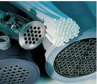
Most hollow fiber products are available in (i) 1" diameter laboratory test cartridges ranging up to 10" diameter for commercial products, (ii) standard commercial cartridge lengths of 25", 43", 48", 60" and 72", (iii) nominal separation ranges from 0.2 micron down to 1,000 MWCO, (iv) Fiber inside diameters from 0.02"(0.5mm) up to 0.106"(2.7mm), (v) Various materials of construction including polysulfone and polyacrylonitrile. Figure 1.6.2-4shows some hollow fiber cartridges of 5, 8 and 10” diameter with endcaps.
The flow pattern in a typical hollow fiber module takes place as shown in Figure1.6.2-4.
Figure 1.6.2-4 Schematic representation of the hollow fiber module cross-section.
The capillary membrane modules consist of a large number of capillary membranes with an inner diameter of 0.2 to 3 mm arranged in a parallel bundle in a shell tube. The feed solution is forwarded into the lumen of capillary membranes and the filtrate, which permeates the capillary wall, is collected in the shell tube. A schematic representation of the module is shown in the Figure 1.6.2-5.
Figure 1.6.2-5 Schematic representation of the capillary membrane module.
Tubular membrane modules are traditionally used for pressure filtration with feed water recirculation through lumen. In such modules, the membrane is cast on the inside surface of a porous tube. Tubular membranes operate in tangential, or cross-flow,
design where process fluid is pumped along the membrane surface in a sweeping type action. The feed solution is pumped through the center of the tube at velocities as high as 6 m/s. These cross-flow velocities minimize the formation of a concentration polarization layer on the membrane surface, promoting high and stable flux and easy cleaning, especially when the objective is to achieve high suspended solids in the MF, UF or NF concentrate. Some tubular membrane modules are shown in Figure 1.6.2-6.
Figure 1.6.2-6 Schematic representation of the tubular membrane module.
There are many advantages using tubular membrane configurations. Besides their rugged construction, they have a distinct advantage of being able to process high suspended solids, and concentrate product successfully and repeatedly to relatively high end point concentration levels without plugging. For juice clarification applications, tubular membrane systems produce the greatest yields and the highest final suspended solids concentration levels. Tubular MF, UF and NF systems do not require significant prefiltration [19].
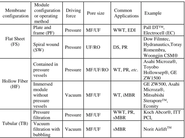
Table 1.6.2-1. Summary of membrane module configurations. Membrane configuration Module configuration or operating method Driving
force Pore size
Common
Applications Example
Flat Sheet (FS)
Plate and
frame (PF) Pressure MF/UF WWT, EDI
Pall DT™, Electrocell (EC) Spiral wound (SW) Pressure UF/RO DS, PR Dow Filmtec, Hydranautics,Toray Romembra, Woongjin CSM® Hollow Fiber (HF) Contained in pressure vessels
Pressure MF/UF/RO WT, PR, etc.
Asahi Microza®, Toyobo Hollowsep®, GE ZW1500 Immersed module without pressure vessels
Vacuum MF/UF WT, iMBR
GE ZW500, Asahi Microza®, Mitsubishi Sterapore™, Econity Tubular (TB) Pressure
filtration Pressure MF/UF
WWT, PR, sMBR
Koch Abcor®, ITT PCI,
Vacuum filtration with bubbling
Vacuum MF/UF sMBR Norit AirliftTM
DS: Desalination, ED: Electrodialysis, PR: Process Recovery, WT: Water Treatment, WWT: Wastewater Treatment
1.7 Membrane operations
The principal objective of a membrane separation process is the separation of a desirable substance from a given mixture. Today, almost all the membrane processes use synthetic membranes. Although biological membranes carry out a number of complicated separations in all life processes, they are not widely used. There are a number of membrane processes which can be defined by considering the following aspects:
• the nature of the species retained by the membrane,
• the nature of the species permeating through the membranes,
• the driving force needed to achieve the desired separation,
There are several membrane separation processes which are of industrial importance today. They are briefly discussed below with respect to their principal characteristics [20].
1.7.1 Microfiltration
Microfiltration (MF) is the process of removing particles or biological entities in the 0.025µm to 10.0µm range from fluids by passage through a microporous medium such as a membrane filter. Although micron-sized particles can be removed by use of non-membrane or depth materials such as those found in fibrous media, only a non-membrane filter having a precisely defined pore size can ensure quantitative retention. This process also requires hydrostatic pressure gradient across the membrane and the pressure used is of the order of 100 kPa or so. The pore size of the membranes decides the size of the particulate matter retained. The process is similar to ultrafiltration and separation takes place by sieving. Membrane filters can be used for final filtration or prefiltration, whereas a depth filter is generally used in clarifying applications where quantitative retention is not required or as a prefilter to prolong the life of a downstream membrane. Membrane and depth filters offer certain advantages and limitations. They can complement each other when used together in a MF process system or fabricated device. The retention boundary defined by a membrane filter can also be used as an analytical tool to validate the integrity and efficiency of a system. For example, in addition to clarifying or sterilizing filtration, fluids containing bacteria can be filtered to trap the microorganisms on the membrane surface for subsequent culture and analysis. MF can also be used in sample preparation to remove intact cells and some cell debris from the lysate. Membrane pore sizes used for these types of separation are typically in the range of 0.05 µm to 1.0 µm.
The most used polymers for MF membranes are the hydrophobicpolyviny1idenfluoride (PVDF), polypropylene (PP), polyethylene (PE), and the hydrophilic materials cellulose esters, polycarbonate (PC), polysulfone/polyethersulfone (PSf/PES), polyimide/polyetherimide and polyetheretherketone (PEEK). The ceramic membranes, which can be used both in micro- and ultrafiltration processes, have superior chemical, thermal, and mechanical stability compared to polymeric membranes, and the pore size can be more easily controlled.
MF membranes are prepared by sintering, track-etching, stretching, or phase inversion techniques. Module configurations include hollow fiber, tubular, plate and frame, spiral wound.
Different solutions can be processed by MF including milk, beer, wine, whiskies, potable water, syrups, edible oils and vinegar. On a molecular weight basis, these membranes can separate or reject macromolecules and generally solute less than 100,000 MW pass through these membranes. The separation mechanism of MF is commonly attributed to a molecular sieving; i.e. passage through the membrane is a function of particle size relative to opening or pore dimensions of the membrane. The operational mechanism of the functional layer of MF is illustrated in figure 1.7.1-1.
Figure 1.7.1-1. Schematic representation of MF membrane function layer.
1.7.2 Ultrafiltration
Ultrafiltration (UF) is the process of separating extremely small particles and dissolved molecules from fluids. The primary basis for separation is molecular size, although in all filtration applications, the permeability of a filter medium can be affected by the chemical, molecular or electrostatic properties of the sample. UF can only separate molecules which differ by at least an order of magnitude in size. Molecules of similar size can not be separated by UF. Materials ranging in size from 1KDa to 1000KDa molecular weight (MW) are retained by certain UF membranes, while salts and water will pass through. Colloidal and particulate matter can also be retained. Ultrafiltration membranes can be used both to purify material passing through the filter and also to collect material retained by the filter. Materials significantly smaller than the pore size rating pass through the filter and can be depyrogenated, clarified and separated from high molecular weight contaminants.
Materials larger than the pore size rating are retained by the filter and can be concentrated or separated from low molecular weight contaminants. UF is typically used to separate proteins from buffer components for buffer exchange, desalting, or concentration. Ultrafilters are also ideal for removal or exchange of sugars, non-aqueous solvents, the separation of free from protein-bound ligands, the removal of materials of low molecular weight, or the rapid change of ionic and/or pH environment. Depending on the protein to be retained, the most frequently used membranes have a nominal molecular weight limit (NMWL) of 3 kDa to 100 kDa and hydrostatic pressures of 0.1-0.5 MPa are used. Ultrafiltration is far gentler to solutes than processes such as precipitation. UF is more efficient because it can simultaneously concentrate and desalt solutes. It does not require a phase change, which often denatures labile species, and UF can be performed either at room temperature or in a cold room. The main hydrodynamic resistance of the membrane is offered by the top layer, while the supporting porous sub layer offers minimal hydraulic resistance. UF membranes are prepared by phase inversion. Materials used are PSf, PVDF, PAN,PEEK and cellulosics such as cellulose acetate. Polymer blends, e.g. with polyvinylpyrrolidone (PVP) are commonly used to increase the hydrophilicity of the membranes. Also the UF process can be operated according to the dead-end and cross flow configurations.UF refers to a scale of separation between microfiltration and nanofiltration, used to purify, concentrate or fractionate macromolecules.
UF membranes reject or separate high molecular weight solutes as well as suspended solids, colloids, and macromolecules. Water and low MW dissolved solids such as salts and sugars pass readily through the membranes (Figure 1.7.2-1).
Some UF membranes can reject particles having a molecular weight of about 1,000 MV, and a few manufacturers claim to make UF membranes which can reject a small percentage of low MW dissolved salts. However, most applications using UF membranes fall in the 10,000 to 100,000 MW ranges. Like MF membranes, the UF separation mechanism is commonly attributed to geometry, i.e. the opening or pore size of the membrane. While some specialty dead end cartridges are used, primarily in the pharmaceutical industry, UF separations are principally done in cross flow mode. Systems operate at a relatively low transmembrane pressure, 0.7 to 10.3bar. Generally, UF membranes require higher pressures than MF membranes because they are “tighter” and offer more resistance to liquid flow through the membrane.
UF is widely used for the recovery and concentration of enzymes and proteins produced by fermentations. The attraction of UF in protein concentration lies in the energy efficiency of the concentration of dilute fermentation broths and the gentle nature of separation which minimises protein denaturation, as the loss of protein activity. The addition of fining agents and then the decanting or filtering through pre-coat filter have been used in the traditional clarification of fruit juices. The application of UF simplifies the process by reducing time and labour and by increasing yield and juice quality [22]. UF is also used to remove particulate, microorganisms and colloidal material from drinking water and thus replaces conventional clarification and disinfection. The ability to separate soluble macromolecules from other soluble species and solvents is the major reason of the use of the UF in many industries such as pulp and paper industries [21]. UF membrane systems conserve energy with minimal operation and labour costs. The ability to retain high concentrates minimises disposal costs for a wide range of industries. In the bid to conserve water, using UF membrane systems to recycle water can yield zero discharge capabilities. Initial setup cost is low and minimal pretreatment chemicals are required compared to conventional systems.
1.7.3 Nanofiltration
The development of nanofiltration (NF) membranes was fairly rapid during the 1970s and 1980s, leading to a “loose RO” membrane process, which was given the name “nanofiltration” at the end of the 1980s.
In this sense, then, NF is a fairly recent development in the range of membrane separation processes, which takes in the upper end (in separation size terms) of reverse
osmosis, and the lower end of ultrafiltration, covering MWCO values of 100 to 1000 Daltons. It deals with materials that are dissolved in a liquid, and not with distinct particles suspended in the liquid. The separation between solute and solvent occurs by diffusion of the molecules of the solvent through the mass of the membrane material, driven mainly by a high transmembrane pressure, and not through any physical hole (pore) in the membrane. Some of the solute molecules may also diffuse through the membrane, either by the process designer's intent, or because the solute has a finite (although very small) diffusion coefficient in the membrane material.
The key difference between NF and reverse osmosis is that the latter retains monovalent salts (such as sodium chloride), whereas nanofiltration allows them to pass, and then retains divalent salts such as sodium sulphate. The membrane separation process known as NF is essentially a liquid phase one, because it separates a range of inorganic and organic substances from solution in a liquid mainly, but by no means entirely, water. This is done by diffusion through a membrane, under pressure differentials that are considerable less than those for reverse osmosis, but still significantly greater than those for ultrafiltration. It was the development of a thin film composite membrane that gave the real impetus to NF as a recognized process with its unique ability to separate and fractionate ionic and relatively low molecular weight organic species. NF membranes are produced in plate and frame form, spiral wound, tubular, capillary and hollow fibre formats, from a range of materials, including cellulose derivatives and synthetic polymers, from inorganic materials, ceramics especially, and from organic/inorganic hybrids.
Recent developments of membranes for NF have greatly extended their capabilities in very high or low pH environments, and in their application to non-aqueous liquids. The plastic media are highly cross-linked, to give long-term stability and a practical lifetime in more aggressive environments. NF membranes tend to have a slightly charged surface, with a negative charge at neutral pH. This surface charge plays an important role in the transportation mechanism and separation properties of the membrane. As with any other membrane process, NF is susceptible to fouling, and so NF systems must be designed to minimize this phenomenon through a proper pretreatment, with the right membrane material, with adequate cross-flow velocities to scour the membrane surface clear of accumulated slime, and by use of rotating or vibrating membrane holders.
Industrial applications of NF are quite common in the food and dairy sector, in chemical processing, in the pulp and paper industry, and in textiles, although the chief application continues to be in the treatment of fresh, process and waste waters.
In the treatment of water, NF finds use in the polishing at the end of conventional processes. It cannot be used for water desalination, but it is an effective means of water softening, as the main hardness chemicals are divalent. At first sight, NF would not seem to have much place in MBR processes, because the higher transmembrane pressure differentials needed for NF are not available in most bioreactor systems, but there are some specialized uses for MBRs in which NF is finding a place. NF membranes are also used for the removal of natural organic matter from water, especially tastes, odors and colors, and in the removal of trace herbicides from large water flows. They can also be used for the removal of residual quantities of disinfectants in drinking water.
Food industry applications are quite numerous. In the dairy sector, NF is used to concentrate whey, and permeates from other whey treatments, and in the recycle of clean-in-place solutions. In the processing of sugar, dextrose syrup and thin sugar juice are concentrated by NF, while ion exchange brines are demineralised. NF is used for degumming of solutions in the edible oil processing sector, for continuous cheese production, in the production of alternative sweeteners and for the cholesterol removal [21]. In aqueous systems, NF uses hydrophilic polymeric materials, such as polyether-sulphone, polyamides and cellulose derivatives. These materials, in contact with organic solvents, quickly lose their stability. Special membranes have therefore been developed to provide the same kind of performance as in aqueous systems, and they are now used for solvent exchange, solvent recovery and separation, for catalyst recovery and for heavy metal removal. A schematic representation of a NF membrane functional layer is shown in figure 1.7.3-1.
1.7.4 Reverse osmosis
Reverse Osmosis (RO) and NF are two very similar technologies. In appearance they are virtually identical and both use essentially the same technology to remove impurities from water or other liquids. In both systems, membranes are used to separate a liquid from contaminants.
RO, also known as hyperfiltration, is the finest filtration known. This process will allow the removal of particles as small as ions from a solution. RO is used to purify water and remove salts and other impurities in order to improve the color, taste or properties of the fluid. It can be used to purify fluids such as ethanol and glycol, which will pass through the RO membrane, while rejecting other ions and contaminants from passing. The most common use for RO is in purifying water. It is used to produce water that meets the most demanding specifications that are currently in place.
RO uses a membrane that is semi-permeable, allowing the fluid that is being purified to pass through it, while rejecting the contaminants that remain. Most RO technology uses a process known as crossflow to allow the membrane to continually clean itself. As some of the fluid passes through the membrane the rest continues downstream, sweeping the rejected species away from the membrane. The process of RO requires a driving force to push the fluid through the membrane, and the most common force is pressure from a pump. The higher the pressure, the larger the driving force. As the concentration of the fluid being rejected increases, the driving force required to continue concentrating the fluid increases.
RO is capable of rejecting bacteria, salts, sugars, proteins, particles, dyes, and other constituents that have a molecular weight of greater than 150-250 daltons.
RO membranes can be made of cellulose triacetate, aromatic polyamide or interfacial polymerization of polyamide and poly (ether urea).
Over traditional evaporation the RO is characterized by low thermal damage to product, reduction in energy consumption and lower capital investments as the process is carried out at low temperatures and it does not involve phase change for water removal [22]. The filtration spectrum illustrating all pressure-driven membrane operations including RO, is depicted in Figure 1.7.4-1.
Figure 1.7.4-1The filtration spectrum
1.7.5.Membrane distillation
Membrane distillation (MD) is a relatively new membrane separation process which might overcome some limitations of the more traditional membrane technologies. In particular, high solute concentrations can be reached and ultrapure water can be produced in a single step. The possibility of an industrial development of this technology is related to the growing commercial availability of membranes of potential interest. When a microporous hydrophobic membrane separates two aqueous solutions at different temperatures, selective mass transfer across the membrane occurs: this process takes place at atmospheric pressure and at temperatures which may be much lower than the boiling point of the solutions. The hydrophobicity of the membrane prevents the transport of the liquid phase across the pores of the partition while water vapor can be transported across them from the warm side, condensing at the cold surface. The driving force is the vapor pressure difference at the two solution membranes interfaces. Because the process can take place at normal pressure and low temperature, MD could be used to solve various wastewater problems, to separate and recover chemicals, and also to concentrate to high osmotic pressures aqueous solutions of substances sensitive to high temperatures. The possibility of using solar, wave or
geothermal energy, or existing low temperature gradients typically available in industrial processing plants is particularly attractive. The fundamental simplicity of traditional distillation is compromised by various factors such as the need for complete removal of all non condensable gases. The use of vacuum pumps, high pressure vessels, deaeration devices, etc. are required for removing the effects of the non condensable gases, with a significant energy consumption. A number of distillation processes have been proposed with the aim of eliminating the need for creating a vacuum [23]. Figure 1.7.5-1 shows the schematic representation of MD process.
Figure 1.7.5-1 A schematic representation of the membrane distillation process: T1, temperature at the hot side; T0, temperature at the cold side; J, flux of the vapor phase.
The most suitable materials for MD membranes include PVDF, polytetrafluoethylene (PTFE) and polypropylene (PP). The size of micropores can range between 0.2and 1.0µm. The porosity of the membrane will range from 60% to80% of the volume and the overall thickness from 80–250 µm, depending on the absence or presence of support. Because MD can be carried out at the atmospheric pressure and at a temperature which can be much lower than the boiling point of the solution, it can be used to concentrate solutes sensitive to high temperature (e.g. fruit juices), also at high osmotic pressure. Therefore MD has received a great attention as a technique for concentrating fruit juices [24, 25].
1.7.6 Osmotic distillation
Osmotic distillation (OD) is a kind of mass transfer driven membrane process where the driving force is the vapour pressure difference between two solutions. Similar that membrane distillation (MD) in case of OD are also used hyrdophobic, porous,
polymeric membranes. For the OD process usually high concentration of osmotic agent, mostly salt solution (NaCl,CaCl2, K2HPO4, K–acetate) or some kind of organic
solutions (polyethylene-glycol, glycerol, etc.) are used which can keep and sustain very low value of vapour pressure during the process. These osmotic agents are able to perform the suitable vapour pressure difference with the high concentration and low vapour pressure value between the two solutions [26-28].OD process is based on the use of two aqueous solutions which have different water activity and a microporous hydrophobic membrane between these solutions. Thus aqueous solutions cannot penetrate into the pores at the liquid-vapour interfaces. As a result, volatile compound molecules (water) evaporate from the higher water activity liquid-vapour interface (liquid food side), cross the pores by diffusion and condense at the lower water activity vapour-liquid interface (osmotic agent side). Figure 1.7.6-1 shows the flow sheet of the OD process [29-32].
Figure 1.7.6-1 Schematic representation of OD
If the operating pressure is kept below the capillary penetration pressure of liquid into the pores, the membrane cannot be wetted by the solutions. OD has been successfully applied to the concentration of liquid foods such as milk, fruit and vegetable juice, instant coffee and tea and various non-food aqueous solutions. This technique can be used to extract selectively the water from aqueous solutions under atmospheric pressure and at room temperature, thus avoiding thermal degradation of the solutions. It is therefore particularly adapted to the concentration of heat-sensitive products like fruit juices.
As compared with RO and MD process, the OD process has the potential advantage which might overcome the drawbacks of RO and MD for concentrating fruit juice, because RO suffers from high osmotic pressure limitation, while in MD some loss of volatile components and heat degradation may still occur due to the heat requirement for the feed stream in order to maintain the water vapour pressure gradient. OD, on the other hand, does not suffer from any of the problems mentioned above when operated at room temperature [33].