Dipartimento di Elettronica, Informazione e Bioingegneria Master of Science in Automation and Control Engineering
Automated Smart Indoor Farming using
IoT
Supervisor
Prof. Marco MARCON
Candidate Shahrukh Ahmed IRFANI – 10559842
2
Acknowledgements
I would like to express my sincere gratitude to my supervisor Professor Marco Marcon at Politecnico di Milano University for the continuous support of my master thesis research project, for his patience, motivation, enthusiasm, and immense knowledge. It would have been difficult to achieve my goals without my supervisor’s constant feedback.
Secondly, I cannot thank enough to Politecnico di Milano University for giving me an opportunity to experience this roller coaster ride of master’s degree in Automation and Control Engineering. Furthermore, I am grateful to all the professors who taught me various subjects of my academic curriculum and lab supervisors who gave me immense knowledge of the subjects in both practical and theoretical aspects.
To conclude, I would like to thank my family members Khursheedunnisa Begum, Zaheda Begum, Vasiur Rehman, Khamarunnisa Begum and Natasha Amjad for their support, motivation, and prayers throughout the journey of my life. Finally, I am extremely thankful and blessed to have my only best friend and my dear brother Mohammed Shahbaz Irfani, for helping me overcome every milestone.
3
Sommario
L'Internet delle Cose e gli smart device che generano e raccolgono dati tramite sensori per inviarli al Cloud fanno parte della vita degli utenti in molti contesti, tra cui la gestione agricola intelligente (smart farming e l’intelligent farm). Questo elevato volume di dati viene archiviato ed elaborato nel Cloud allo scopo di ottenere conoscenze e informazioni preziose per le diverse organizzazioni. Il concetto di coltivazione indoor è molto recente e sta crescendo in un vasto mercato multimilionario. Con l'avvento delle tecniche di apprendimento automatico (machine learning), la pre-elaborazione dei dati e le capacità decisionali possono essere ampiamente automatizzate: un'idea simile viene proposta per coltivare specifiche erbe e piante utilizzando condizioni di crescita automatizzate quali l'intervallo di umidità del suolo, i livelli di intensità della luce e la miscela di acqua e nutrienti oltre alla frequenza di pompaggio.
Il progetto inizialmente si concentra sul confronto delle tecnologie esistenti, valide sia da un punto di vista scientifico che commerciale. Una revisione dettagliata dello stato dell'arte identifica i problemi chiave della ricerca e il progetto si concentra principalmente sulla progettazione e sull'implementazione di un sistema di agricoltura indoor intelligente automatizzato tramite interfaccia cloud opensource che utilizzando la piattaforma ThingsSpeak IoT. Il sistema è interamente gestito utilizzando un computer a scheda singola, Raspberry Pi Model 3B + con sistema operativo Raspbian Linux. Una suite di sensori di umidità del suolo composta da sensori resistivi e capacitivi, in aggiunta al sensore di temperatura e umidità forniscono misurazioni accurate dei dati che vengono inviati al cloud in tempo reale. L'algoritmo implementato utilizzando il linguaggio di programmazione Python gestisce l'automazione del sistema e i segnali logici intelligenti vengono trasmessi ai relè per l'irrigazione istantanea e alle luci utilizzate per la crescita delle piante. Il sistema IoT proposto automatizza il ciclo di crescita delle piante (quali colture o erbe aromatiche) in base a specifiche condizioni di crescita (temperatura, umidità e livelli di intensità luminosa) di quella particolare pianta senza intervento manuale da parte degli utenti.
Parole chiave: l’intelligent Farm, Agricoltura Indoor, Internet of Things, Raspberry pi, controllo in tempo reale, rilevamento in tempo reale, Thingspeak, Automazione, idroponica, aeroponica
4
Abstract
The Internet of Things and the smart devices that generate and collect data through sensors to send it to the Cloud are part of the life of users in many contexts, including smart farming and intelligent farm. This volume of data is stored and processed in the Cloud, with the purpose of obtaining knowledge and valuable information for organizations. The concept of Indoor farming is very new and is growing into a vast multimilliondollar market. With the advent of machine learning techniques, data pre -processing and decision-making capabilities can be widely automated, a similar idea is proposed to grow custom user preferred herbs using automated growing conditions like soil moisture range, Light intensity levels and water-nutrient mixture pumping frequency.
The project initially focuses on comparing the existing technologies both scientifically and commercially viable. A detailed review of the state of the art identifies the key research problems and the project mainly focuses on design and implementation of an Automated smart indoor farming system with enhanced opensource cloud dashboard interface using ThingsSpeak IoT platform. The system is entirely operated using the Raspberry Pi Model 3B+ single board computer with Raspbian Linux operating system. A soil moisture sensor suite comprising of resistive and capacitive s ensor along with the temperature and humidity sensor provide accurate data measurements which are sent over to the cloud in real time. The smart algorithm implemented using Python programming language handles the automation of the system and smart logic si gnals are conveyed to the relays for timely irrigation and switching the grow lights for plant growth. The proposed IoT system automates the growth cycle of the plants(crops, herbs) based on specific growing conditions(temperature, moisture and light intensity levels) of that particular plant without manual intervention from the users.
Keywords: Intelligent Farm, Indoor Farming, Internet of Things, Raspberry pi, Remote Control, Remote Sensing, Thingspeak, Automation, Hydroponics, Aeroponics
5
Table of Contents
Acknowledgements ... 2 Sommario... ... 3 Abstract... ... 4 List of Figures ... 7 List of Tables ... 9 Chapter 1... ... 10 Introduction ...10 1.1 Structure ... 11 1.2 Humidity Sensors ... 121.2.1 Capacitive Humidity Sensor ... 12
1.2.2 Resistive Humidity Sensors ... 14
1.2.3 Thermal Humidity Sensors ... 15
1.3 Sensor Parameters ... 16
1.4 Sensor Calibration Gravimetric Method ... 17
1.5 Water-Soil Characteristics ... 17
1.6 Indirect Method ... 18
1.7 Commercial Soil Moisture Sensor ... 19
1.8 NIR Sensor ... 21
1.9 Scientific Analysis ... 27
Chapter 2... ... 32
Overview... ... 32
2.1 Motivation ... 32
2.2 Brief Description of Plantoid Project ... 33
2.3 Problem Statement ... 34
2.4 Project Description ... 34
Chapter 3... ... 35
System Design and Implementation ... 35
3.1 Hardware Components ... 35
6
3.1.2 DHT22 AM2302 Digital Temperature and Humidity Sensor Module (Digital
Output)... ... 42
3.1.3 Capacitive Soil Moisture Sensor v1.2 (Analog Output) ... 43
3.1.4 Resistive Soil Moisture Sensor (Analog Output)... 44
3.1.5 LED indoor grow lights ... 45
3.1.6 MCP3008 Analog to Digital Converter IC ... 47
3.1.7 Micro Submersible Mini Water Pump DC 3-6 V (Actuator) ... 49
3.1.8 Li-Polymer Battery Bank 10000 mAh ... 50
3.1.9 Cooling Fan DC ... 51
3.1.10 Relay Board Module - 4 Channel 5V ... 52
3.2 Design Setup ... 54
3.3 Hardware Architecture ... 55
3.3.1 EasyEDA... 55
3.4 Software Architecture ... 59
3.4.1 Remote Desktop Connection ... 60
3.4.2 Software Design – an approach using Python Programming Language ... 64
3.4.3 Interfacing MCP3008 Analog to Digital Converter IC with the Raspberry Pi ... 66
3.4.4 Interfacing the DHT22(Temperature/Humidity Sensor) with the Raspberry Pi . 67 3.4.5 Interfacing the Raspberry Pi to the ThingSpeak IoT Cloud Platform ... 67
Chapter 4 69 System Testing and Performance Evaluation ... 69
4.1 System Testing ... 70
4.2 ThingSpeak IoT Data Visualization ... 74
4.3 System Power Consumption and Energy Cost Calculation ... 76
4.3.1 Power Consumption and Energy Cost of Raspberry Pi ... 76
4.3.2 Power Consumption of Actuators ... 76
4.3.3 Autonomy on Battery Bank ... 77
4.4 Cost Analysis ... 78
Chapter 5... ... 79
Future Scope and Conclusion... 79
Acronyms... ... 81
Appendix... ... 83
A.1 Configuring the Raspberry Pi ... 83
A.2 Using the GNU Nano Editor for Software Scripting. ... 92
A.3 Implementing the Software Architecture and the Automation Logics of the System using Python 3 and GNU Nano Editor. ... 94
7
List of Figures
Figure 1. 1 Capacitive RH sensors ... 13
Figure 1. 2 RH sensitive test subject as dielectric to observe the changes in the frequency of oscillator. ... 13
Figure 1. 3 Top and cross section view of capacitive humidity sensor. ... 14
Figure 1. 4 Resistive Humidity Sensor ... 15
Figure 1. 5 Thermal Conductivity Humidity Sensor ... 16
Figure 1. 6 Soil Texture Triangle (USDA Natural Resources Conservation Service) ... 17
Figure 1. 7 A comparison of Sensing Volume(m3) vs commercially available sensor ... 20
Figure 1. 8 A comparison of operating frequency (MHZ) vs commercially available sensor ... 20
Figure 1. 9 Thermal Conductivity Humidity Sensor ... 22
Figure 1. 10 NIR Sensor case schematic ... 23
Figure 1. 11 NIR Sensor embedded in a Robotic Root Tip of diameter 2cm. ... 24
Figure 1. 12 NIR Sensor housing case. ... 25
Figure 1. 13 NIR Sensor Schematic Layout ... 26
Figure 1. 14 Pulse pattern for LED’s ... 26
Figure 2. 1 Prototype of Plantoid Project ... 33
Figure 3. 1 Raspberry Pi Model 3B+ - Parts ... 36
Figure 3. 2 Broadcom BCM2837 SoC ... 36
Figure 3. 3 Gigabit Ethernet Controller ... 37
Figure 3. 4 dual-band radio module ... 37
Figure 3. 5 Power-over-Ethernet HAT Module pins ... 38
Figure 3. 6 Power Management Integrated Circuit (PMIC) ... 38
Figure 3. 7 Raspberry Pi Model 3B+ Pinout ... 39
Figure 3. 8 DHT22 Pinout ... 42
Figure 3. 9 Capacitive Soil Moisture Sensor v1.2 ... 43
Figure 3. 10 Resistive Soil Moisture Sensor ... 44
Figure 3. 11 Infinity full spectrum LED Plant grow lights ... 45
Figure 3. 12 LED Plant grow lights – advanced features. ... 45
. Figure 3. 13 LED Plant grow lights – illumination modes ... 46
Figure 3. 14 MCP3008 Analog to Digital Converter IC ... 47
Figure 3. 15 MCP3008 Analog to Digital Converter IC – Pinout ... 47
Figure 3. 16 Micro Submersible Mini Water Pump ... 49
Figure 3. 17 Syska 10000 mAh battery bank ... 50
Figure 3. 18 Cooling Fan DC ... 51
Figure 3. 19 4 Channel 5V Relay Board ... 52
8
Figure 3. 21 System Level Block Diagram ... 54
Figure 3. 22 Circuit Connections – Raspberry Pi 3B+ ... 55
Figure 3. 23 Circuit Connections – Sensor Interfacing with MCP3008 ... 56
Figure 3. 24 Circuit Connections – Actuators with the Relay Module ... 57
Figure 3. 25 Circuit Connections – DHT22 Temperature/Humidity Sensor ... 58
Figure 3. 26 Automated Smart Indoor Farming using IoT – Flowchart Diagram ... 59
Figure 3. 27 Raspberry Pi Configuration – Enabling VNC Server ... 61
Figure 3. 28 Raspberry Pi Configuration – VNC Server ... 62
Figure 3. 29 Thingspeak IoT Cloud Platform - Architecture ... 67
Figure 4. 1 Experimental Setup - Prototype ... 69
Figure 4. 2 Test Case - mv > θ ˄ (t > 0 ˄ t < 8) ... 70
Figure 4. 3 Test Case - mv < θ ˄ (t > 0 ˄ t < 8) ... 71
Figure 4. 4 Test Case - mv > θ ˄ ⌐(t > 8 ˄ t < 16) ... 72
Figure 4. 5 Test Case - mv < θ ˄ ⌐(t > 8 ˄ t < 16) ... 73
Figure 4. 6 DHT22 Sensor (Temperature) – Time Series Visualization ... 74
Figure 4. 7 DHT22 Sensor (Humidity) – Time Series Visualization ... 75
Figure 4. 8 Resistive Soil Moisture Sensor (Moisture %) – Time Series Visualization ... 75
Figure 4. 9 Capacitive Soil Moisture Sensor (Moisture %) – Time Series Visualization ... 75
Figure 5. 1 NASA Vision of Indoor Farming on Mars. ... 79
9
List of Tables
Table 1. 1 Commercial Humidity Sensor classification ... 19
Table 1. 2 Scientific Analysis ... 31
Table 3. 1 MCP3008 Analog to Digital Converter IC – Pinout ... 48
Table 4. 1 Test Cases vs Actuator State ... 73
Table 4. 2 Pi State vs Power Consumption ... 76
10
Chapter 1
Introduction
The current situation of the world demands the urgent need for sustainable food production. Sustainability means the ability to be maintained at a certain growth level. According to recent statistics[40], the current food production is carried out on deforested lands, smothering crops with toxic pesticides, and killing natural habitat of the wildlife. Urbanization and Population growth further impacts the problem of food production. Furthermore, we must protect the welfare and financial security of farmers because farming is the backbone of country’s economic growth. The problem of water scarcity is age old and every year countries are affected due to drought and shortage of water resources. In several parts of the world, Industrial wastes are released in the nearby areas which causes infertility in the soil. The right choice of soil and sufficient supply of water can lead to a healthy growth of plantlife. Indoor Farming is a method of growing crops or plants usually on a large scale entirely indoors. It can be further classified based on the choice of growing medium. Hydroponic systems as the name suggests uses water as the primary growing medium and Aeroponic systems utilizes water-nutrient mixture as the growing medium instead of soil. The main advantages of Indoor Farming over traditional farming methods are listed below:
Resource Optimization: Aeroponic Systems requires 95% less water as compared to traditional farming. This technology is a huge breakthrough as freshwater shortage is a huge problem and currently 1% of the worlds water is accessible for drinking. The future trends indicate that the water scarcity issue is going to worsen in the coming years.
Faster Supply Chain: Shorter suppy chains can tackle the program of food wastage. According to a recent survey[40], currently 30% of food waste is lost in the supply chain. This also promotes farmers to grow crops yearround which means they don’t have to rely on buying in produce from the overseas.
Eliminating the usage of Fertlizers and Pesticides: The usage of fertilizers and pesticides have increased the production yield of crops but on the other hand is a major
11
public health concern and also affects the natural habitat of insects and wildlife. Indoor Farming takes inspiration from organic farming eliminating the usage of toxic chemicals and growing crops in controlled environment.
Climate Control: Climate Change and natural disasters have caused a huge loss to the crop production worldwide every year. Unpredictable weather conditions and torrential rains have also devasted the crop yield and caused huge economic losses throughout the world. In controlled growing environment, the food productions can be consistent irrespective of changing weather conditions. The plantlife is subjected to artificial growing conditions like growing lights which can be powered through renewable energy sources.
1.1
Structure
The structure of the thesis includes:
• Chapter 1 - Introduction contains basics of Humidity Sensors, types and classifications based on working principle. It also lists down the pro and cons of using various sensors and sensor calibration methods based on water-soil characteristics. The chapter also discusses the possibility to integrate NIR Sensor which is the best in class sensor for applications involving measuring accurate moisture levels. The scientific analysis discussed later in this chapter helps use to the identify the key design problems and gives an insight to tackle the research problem.
• Chapter 2 - Motivation for the proposed thesis work and its background history. This chapter presents the problem statement and project description giving an initial understanding of the key concepts and basic ideas of the project.
• Chapter 3 - System Design and Implementation is presented with a high level emphasis on Hardware and Software Architecture. This chapter also discuss about the design elements of the system which are the hardware components and the software tools used in the project.
• Chapter 4 - System testing and Performance Evaluation is the main focus of this Chapter. The experimental prototype of the system is illustrated and key functionalities are presented. The system test results based on the desired expectations have been described by extensive testing under various test cases. The graphical visualizations of the sensor data is shown and inferences have been outlined by visual inspections. Finally, the Energy costs and the overall cost analysis of the system are calculated which are the essential parameters in evaluating the system performance.
12
• Chapter 5 - Future Scope and Conclusion. This chapter concludes the thesis work by identifying the goals achieved and the future scope of the project. • Acronyms - This section lists down the abbreviations used in this thesis work. • Appendix - The Thesis project software code and the system configuration is
documented in this section.
• Bibliography - This section is composed of the research citations and references used during the thesis work.
1.2
Humidity Sensors
Humidity Sensor (Hygrometer)[17] senses, measures and reports both moisture and air temperature. Relative Humidity (RH) is the ratio of partial pressure of water vapor to the equilibrium vapor pressure of water vapor at a given temperature.
Humidity sensors work by detecting changes that alter electrical currents or temperature in the medium.
1.2.1 Capacitive Humidity Sensor
A capacitive humidity sensor measures relative humidity by placing a thin strip of metal oxide between two electrodes. The metal oxide’s electrical capacity changes with the relative humidity of the medium.
Working Principle
A simple Capacitive RH Sensor can be made from an air-filled capacitor as the moisture in the atmosphere changes its permittivity. But for practical applications, air as a dielectric is not feasible. Hence, the space between the capacitor plates is usually filled with an appropriate dielectric material (isolator), whose dielectric constant varies when it is subjected to change in humidity. The common method of constructing a capacitive RH sensor is to use a hygroscopic polymer film as dielectric and depositing two layers of electrodes on the either side. Figure 1.1 demonstrates the construction of Capacitive Humidity Sensors.
13
Figure 1. 1 Capacitive RH sensors
Another way to use the capacitive RH sensors is to observe the changes in the frequency of the oscillator constructed using a capacitor with RH sensitive test subject as dielectric [17]. The test samples are placed between two plates (which form the capacitor electrodes) to form a capacitor in the LC Oscillator circuit. The frequency of the oscillator changes with humidity surrounding the test sample. The figure 1.2 illustrates the changes in frequency of oscillator when a test sample is placed between the capacitor plates.
Figure 1. 2 RH sensitive test subject as dielectric to observe the changes in the frequency of oscillator.
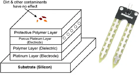
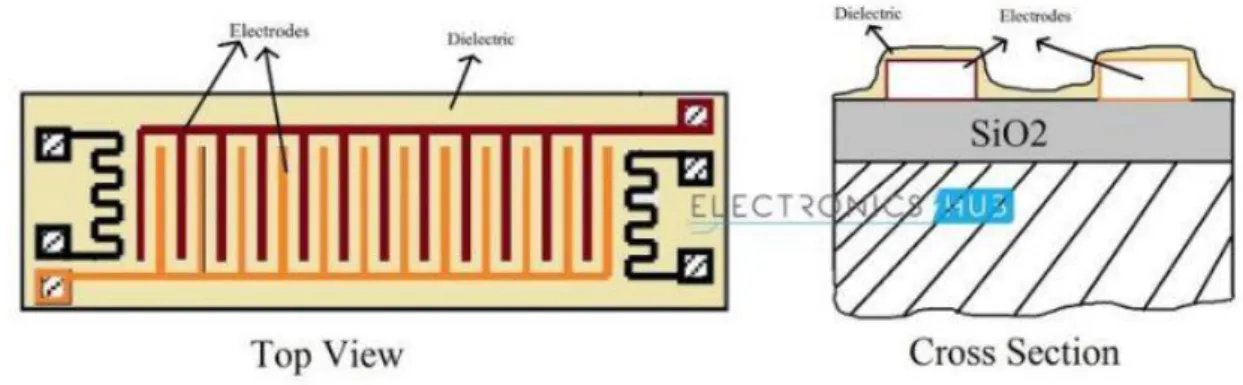
The construction of a thin thermostat polymer film based capacitive RH Sensor is fabricated on a silicon substrate. On this substrate, two metal electrodes made of either aluminium, platinum or chromium are deposited. The shape of these electrodes is carved out such that, the electrodes form an interdigitated pattern. On top of this layer, a dielectric layer is deposited. Figure 1.3 shows a top and cross section view of the capacitive humidity sensor. Note: The two temperature sensitive resistors are deposited on the same substrate to provide temperature compensation.
14
Figure 1. 3 Top and cross section view of capacitive humidity sensor. Advantages
• The capacitive type sensors are linear and can measure relative humidity from 0% to 100%.
• These are the only types of full-range relative humidity measuring devices down to 0% relative humidity.
• This low temperature effect often leads them to being used over wide temperature ranges without active temperature compensation.
• With proper calibration, Capacitive type humidity sensors can yield precise process measurements.
Disadvantages
• The distance from the sensor and signaling circuit is very limited. 1.2.2 Resistive Humidity Sensors
Resistive Humidity Sensors utilize ions in salts to measure the electrical impedance of atoms. As humidity changes, the resistance of the electrode changes on either side of the salt medium.
Working Principle
The Resistive Humidity Sensor is usually made up of materials with relatively low resistivity and this resistivity changes significantly with changes in humidity. The relationship between resistance and humidity is inversely exponential. The low resistivity material is deposited on top of the two electrodes as depicted in figure 1.4.
The electrodes are placed in interdigitated pattern to increase the contact area. The resistivity between the electrodes changes when the top layer absorbs water, and this change can be measured with the help of a simple electrical circuit.
15
Figure 1. 4 Resistive Humidity Sensor
Some of the commonly used materials are salt, specially treated substrates, solid poly-electrolytes and conductive polymers. Modern Resistive Humidity Sensors are coated with ceramic substance to provide extra protection. The electrodes in the sensor are usually made of noble metals like gold, silver or platinum.
Advantages
• They are compact in size and are low cost.
• The distance between the sensor and signal circuit can be large (suitable for remote operations).
• They are highly interchangeable as there are no calibration standards. Disadvantages
• Resistive Humidity Sensors are sensitive to chemical vapours and other contaminants.
• The output readings may shift if used with water soluble products. 1.2.3 Thermal Humidity Sensors
Thermal Conductivity Humidity Sensors are also known as Absolute Humidity (AH) Sensors as they measure the Absolute Humidity. Absolute Humidity (AH) is the ratio of mass of the water vapour to the volume of the air. If m is the mass of the water vapour and V is the total volume i.e. volume of air and water vapour mixture, then Absolute Humidity AH is given by
𝐴𝐻 = 𝑚/𝑉
Absolute Humidity doesn’t take temperature in to account but it changes with temperature and pressure. Thermal Conductivity Humidity Sensors measure the thermal conductivity of both dry air as well as air with water vapor. The difference between the individual thermal conductivities can be related to absolute humidity.
16
Working Principle
The best component to accomplish thermal conductivity-based humidity sensor is thermistor. Hence, two tiny thermistors with negative temperature coefficient are used to for a bridge circuit. In that way , one thermistor is hermetically sealed in a chamber filled with dry Nitrogen while the other is exposed to open environment through small venting holes. When the circuit is powered on, the resistance of the two thermistors is calculated and the difference between those two values is directly proportional to Absolute Humidity (AH).
Figure 1. 5 Thermal Conductivity Humidity Sensor Advantages
• It is suitable for high temperature environments and high corrosive stations.
• It is durable and has higher resolution compared to other types of Humidity sensors. Disadvantages
• When exposed to any gas with thermal properties different than Nitrogen, it might affect the process measurements.
1.3
Sensor ParametersAccuracy: Every sensor has its own calibration curve, based on a 9 point system. It basically pitches the pros against the cons of the particular sensor.
Linearity: It indicates the voltage deviation from the best fit-straight line (BFSL) value and the measured output Voltage converted to relative humidity.
Reliability: The measurements often cause the sensor to fall out of sync. However for a sensor applications, it should always provide reliable measurements.
17
Repeatability: The measurements from a sensor shouldn’t drift apart. Repeatability is the measurement of drift among measurements of single quantity.
Response Time: Typically the time taken by a sensor to rise to 66%(rise time) or fall to 33%(fall time) of maximum output voltage is known as the response time.
1.4
Sensor Calibration Gravimetric Method
The measurement procedure for sensor calibration is as follows:
First, empty container is weighted. It is then filled with dry soil samples and weighted. Then, soak the container contraining the dry soil sample with water for 24 hours until the soil becomes saturated. The soil in the container is weighted once a day during 8 days data retrieval. Degradation of the soil weight in the container is defined as the water that evaporates within one day of experiment. Then, the soil moisture content is calculated with the following equation:
𝑺𝒐𝒊𝒍 𝒎𝒐𝒊𝒔𝒕𝒖𝒓𝒆(%) = Weight of water contained in the soil Weight of dry soil samples
This method is sometimes also used as a direct method used in measurement of soil-moisture content.
1.5
Water-Soil Characteristics
Water availability in the soil either as ground water or soil water is influenced by physical properties of the soil such a s structure, texture, porosity and fraction. These properties indirectly effect the soil-water holding capacity. The availability of soil-water can be measured by direct or indirect method. Measurement of soil-water level by direct method can be determined by using the mass difference of soil sample before and after dried. While determining the soil water using indirect method is usually conducted by using the calibrated variable which has relation to the water content.
18
SPAW model[18] developed by United States Department of Agriculture is a water budgeting tool for farm fields, ponds, and inundated wetlands. It is used to simulate soil water tension, conductivity and water holding capability based on the soil texture, with adjustments to account for gravel content, compaction, salinity, and organic matter. Soil texture triangle is a graphical tool to visualize and understand the meaning of soil texture names.
1.6
Indirect Method
It predicts the soil moisture content of the sample based on the change of soil-water electrical properties which varies according to the changes of soil validity.
Indirect measurement is divided into two methods:
• Conductance Method: A sample is placed between two electrodes. Electrical current is flowed between the two electrodes.
• Capacitance Method: The same sample is again placed between both electrodes. By using two parallel plates, which function as capacitor while the sample works as a dielectric material. The moisture content of the sample is predicted from the capacitance of the capacitor.
The sensor measures the amount of water in the soil by volume using the properties of capacitance. It rapidly applies voltage to the positive electrode, then removes it. This induces electromagnetic field in the soil, and the time it takes for the charge between the electrodes to stabilize is given as:
𝑡 = 𝑅𝐶 lnV − Vf Vi − Vf
R: Soil resistance C: Capacitance
V: measured voltage at time instant t Vi: Voltage at the beginning of the process Vf: Applied Voltage
Since the capacitance of a capacitor is dependent on the relative dielectric permittivity of the material between the electrodes, varying this parameter will change the total capacitance and thus the time it takes to bring it up to charge. Water has a higher relative dielectric permittivity than minerals present in the soil, which changes the capacitance.
19
1.7
Commercial Soil Moisture Sensor
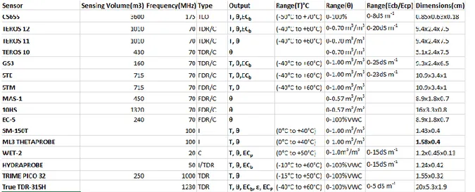
A few of the widely used commerically available moisture sensors are classified based on various parameters like sensing volume, frequency, type, measurement range and dimensions and listed down in the table 1.1
Table 1. 1 Commercial Humidity Sensor classification
All units of measurement in SI system. All the above sensors are in compliance with SDI-12 communication protocols.
ABBREVIATIONS:
ECb Bulk Electrical Conductivity
ECp Pore water Electrical Conductivity
TDR Time Domain Reflectrometry TLO Transmission Line Oscillation ε real di-electric permittivity I Impedance
C Capacitance R Resistance T Temperature
20
Figure 1. 7 A comparison of Sensing Volume(m3) vs commercially available sensor Clearly, from figure 1.7 the campbell scientific CS655 is superior than other sensors interms of sensing volume. It is multiparameter smart sensor that uses innovative techniques to monitor soil volumetric-water content, bulk electrical conductivity, and temperature. It outputs an SDI-12 signal that many data loggers can measure.
Figure 1. 8 A comparison of operating frequency (MHZ) vs commercially available sensor Figure 1.8 illustrates that the IMKO’s TRIME probes and ACCLIMA’s TRUE TDR sensor measure moisture and conductivity very precisely at a frequency of 1GHz with a better and more exact separation of moisture and conductivity in comparison to capacitive probes with lower frequencies.
21
The commercial moisture sensors are classified based on it working type. 1. Resistive
2. Dielectric
➢ TDR(Time Domain Reflectometry) ➢ FDR(Frequency Domain Reflectometry) 3. Thermal
4. Neutron Probe
5. Gamma Ray Attenuation 6. Near Infrared Reflectometry.
• Gravimetric Method: Gold standard , most reliable, high accuracy and reliability. Despite its advantages, it is time consuming, destructive and unrepeatable.
• TDR and FDR type sensors can only be used to measure Volumetric soil moisture after proper calibration. Soil sensitivity poses unpredictable effects on soil moisture measurement.
• Capacitance technique: It is commercially available. Its performance is dependent on the size of the sensor.
• Neutron Probe requires trained operator due to the use of Radioactive source which is potentially hazardous to the environment.
• Gamma Ray Attenuation method can determine the moisture content at soil surfaces(up to 1-2 cm) but high cost and difficulty to use limit its applicability. • Near Infrared Reflectometry is the potential technology which can factor out
the problems resulting from other technologies. A custom NIR sensor, discussed in the following section is the key solution interms of accuracy and portability in most of the applications.
1.8
NIR Sensor
Soil moisture has absorption bands of 970, 1200, 1450 and 1940 nm in the NIR spectrum. Two strong adsorption bands have been reported at and 1450 and 1940 nm due to first overtone of bending band and the combination of stretching band and OH-bending band. A higher moisture content is correlated with deeper water absorption band and vice versa. From a study by Ben-Dor et al 2008 and Zhu et al 2010 [19], they predicted soil moisture content for three types of soil using wavebands 1400,1940 and 2250 nm. The results indicate most significant correlation between soil moisture and reflectance was identified at 1400nm for disturbed soil samples(R2 = 0.996, RMSE = 0.01 cm3 cm-3) and at 1940nm for both cored (R2 = 0.969, RMSE = 0.019 cm3 cm-3) and
22
Expected Outcomes
• To achieve strong liear correlation between soil moisture and relative absorption depths for different soils.
• The reflectance model is dependent of soil type.
• Soil moisture is predicted using an algorithm which is designed for estimating soil moisture using the relative absorption depth from reflectance data of 1800 nm and 1940 nm Wavelength.
• The results agree well with measurements obtained from gravimetric method. • It can be used in laboratory and field applications.
Sensor Design
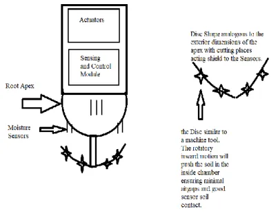
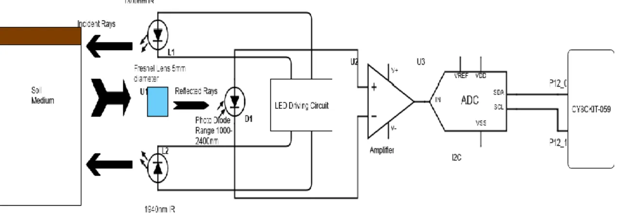
The Sensor is composed of Infrared Led as light source generating wavelengths of 1940 nm (Strong water absorption band) and 1800 nm(Weak water absorption band). The Photodiodes are used to receive the reflectance. Sensor case(PVC) of dimensions 2cm diameter at the open end, 5.5cm diameter at the lower end and 2.5cm in height with a possibility to scale down the dimensions. A Light detector is installed at the top of the sensor case, six LED’s are arranged circularly around the light detector. All of the LED’s are angled at 45° to the normal so that the beam of light all LED’s are focused on a plane resulting in central irradiated area of approximately 8mm in diameter at the soil surface.
Typical Layout Configuration
23
The sensor comprises of 2 modules – Actuating Module, Sensing and Control Module. The disc shaped protector comprising sharp blades is affixed at one end of the sensor, this also acts as a shield to the modules of the sensor. The sensor design makes it easy to penetrate inside the growing medium or hostile applications.
Working Prinicple
During operation, the radiations from the LED’s are directed to the soil surface at a fixed distance of 15mm. After interacting with the soil surface, a fraction of the refle cted light is reflected to the receiving detector and the rest is lost due to scattering absorption and transmission.
The detector has wide angular response to incident radiation and no light reaches the detector directly from the LED’s. To generate maximum average power, the infrared LED emits a pulse signal to produce 600mA of current for 700µS. Normally all the LED’s at both wavelength of 1940 nm and 1800 nm are under off status. When measurement is started, reference LED’s is turned on for a short period of 700µs and the reflectance of the reference light is detected and collected by the control unit. Afterwards the measuring LED’s is turned on and the reference LED is turned off after 700µs . The procedure is repeated once every one second. Upon receiving the light within the spectral response range, the receiving photodiode produces a Voltage signal that is proportional to the amount of incoming light energy. The output Voltage is sent directly to the low-noise amplifier before its input to the data storage unit. The amplifier – a high pass filter can attenuate signals with lower frequencies.
The InGaAsSb photodiode has a spectral response range of 900-2400 nm and a 0.3mmx0.3mm square sensing area with peak sensitivity at 2100 nm. The InGaAsSb photodiode is very sensitive at wavelengths of 1800 nm and 1940 nm.
24
NIR Sensor [19] utilizes the power of opto-electronics and Infra-red spectroscopy to measure soil moisture content, moisture data plays a key role in irrigation scheduling and health of an indoor farming plant.
Robots deployed in irrigation fields can be embedded with NIR sensor, this removes the process of manual intervention problem of traditional sensors. Typically, t he holes should be drilled inside the soil based on the dimensions of the sensor and it is manually deployed. The main draw back associated with NIR Sensor is high cost of opto -electronics and is currently limited to research-oriented applications.
In future, the NIR sensor can be deployed in smart farming applications and a custom sensor setup for this applications is identified and depicted below.
Design Setup
Figure 1. 11 NIR Sensor embedded in a Robotic Root Tip of diameter 2cm.
In some research oriented applications, NIR sensor can be advantageo us interms of design dimensional requirements. In figure 1.11, the opposite side of the Blue circle is where the custom NIR Sensor is placed.
25
Figure 1. 12 NIR Sensor housing case.
An example of NIR sensor housing is shown in figure 1.12.
Dimensions:
1800nm IR LED: 3mm Fresnel Lens: 5mm 1900nm IR LED: 3mm
During operation, the radiations from the LED’s are directed to the soil surface at a fixed distance of 15mm. After interacting with the soil surface, a fraction of the reflected light is reflected to the photodiode through the Fresnel lens and the rest is lost due to scattering absorption and transmission. The photodiode is placed at the focal point of the Fresnel lens. To generate maximum average power, the infrared LED emits a pulse signal to produce 600mA of current for 700µS. Normally all the LED’s at both wavelength of 1940 nm and 1800 nm are under off status. During the operation, the reference LED’s is turned on for a short period of 700µs and then the reflectance of the reference light is detected and collected by the control unit. Afterward the measuring LED’s is turned on and the reference LED is turned off after 700µs . The procedure is repeated once every one second. Upon receiving the light within the spectral response range, the receiving photodiode produces a voltage signal that is proportional to the amount of incoming light energy. The output voltage is sent directly to the low-noise amplifier before its input to the data storage unit. The amplifier – a high pass filter can attenuate signals with lower frequencies. The amplified output is passed through an I2C Analog to Digital Converter and the output is connected to the ports of the CY8CKIT-059 prototyping kit.
26
Figure 1. 13 NIR Sensor Schematic Layout
27
1.9
Scientific Analysis
Name of Research Paper Description
Internet of Things (IoT): A vision, architectural elements, and future directions [1]
IoT based smart agriculture[2]
Design and Development of IoT and Cloud Based Smart Farming System for Optimum Water Utilization for Better Yield[3]
Development of Raspberry Pi & IoT Based monitoring &
controlling devices for
agriculture[4]
Through this paper, the author presents a vision and motivates the application domain of IoT following a new approach. Cloud technologies and WSN’s are used. It also depicts the ways of dealing with challenges and future innovations by compiling with the technologies involving cloud.
In this paper, the author shows how the advancement in agricultural field is controlled by the use of various IoT technologies like Smart system GPS & remote controlled robots for performing activities like weeding, spraying, moisture sending, bird-animal scaring, keeping vigilance etc. It also shows how real time accurate field data is obtained through Smart irrigation. In this paper, Smart Warehouse System is also shown.
The author generates a statistical analysis of a microcontroller program which helps in maintaining the soil balance after a certain level of dryness that is contained in the soil. The use of sensors helps to balance and monitor the temperature, moisture and humidity of the soil for increasing the yielding capacity. The cloud facility involved is used for storing the data obtained.
In this paper, the authors explain about the sensor networks and its applications in agricultural fields. The data collected is stored in cloud and monitored using IoT device. Improvement in efficiency of agricultural sector is handled using raspberry pi & sensors. The result focuses on soil moisture, humidity & temperature of the field.
28 Name of Research Paper Description
Sensor Network Data Acquisition & Task Management for Decision Support of Smart Farming[5]
IoT based Smart Water
Management with Sensors
Agriculture Stick for Live
Temperature and Moisture
monitoring[6]
Plant monitoring using image processing, Raspberry pi & IoT[7]
Design and Implementation of a Connected Farm for Smart Farming System[8]
In this paper, the author focuses on applied agriculture using comprehensive models of IoT. Data acquisition & data analysis are handled using sensors and measure of control and task management are taken care. This analyzed data is further used in modeling and system design.
The author shows the Implementation of smart water management system involving certain areas of agriculture which involves distribution of water evenly between the crops for proper plantations. This paper also shows the use of a smart stick based on agricultural field is used for depicting activities like temperature, humidity, moisture etc. It is proposed for validating system accuracy with real time parameters.
The author in this paper describes the need of a device that is required to identify diseases affecting the growth criteria of plants. They have used technologies like Digital image processing in order to identify the type of disease caused by the pathogen and IoT device and sensors.
Through this paper, the author shows the research and analysis which provide a suitable environment for growing crops by proposing a design for smooth deployment of IoT device into connected farms. In this paper, there are basically three components – sensors (temperature, humidity, CO2, illumination) & controllers (sprinkler, LED light, heater, AC); IoT gateway (&Cube) and IoT service Platform (Mobius).
29 Name of Research Paper Description
Smart Farming using IoT[9]
Decision support system for smart farming with hydroponic style[10]
Technology based streamlined agro-farming techniques[11]
A smart irrigation system to automate irrigation process using IoT and Artificial Neural Network[12]
The author depicts a better way of irrigation by penetrating water system which helps in gathering information regarding the crops such as humidity, moisture and dampness present in the soil.
The authors in this paper describe the need and implementation of Smart farming with the help of hydroponic farming technique which results in aiding facilities that could help farmers to grow crops in areas where it is impossible to cultivate crops. This method aims to lower decaying and toxicity of plant allowing fishes to breed with ease.
This paper focuses on cultivating a specific(Tomato) plant using technologies like smart farming and IoT. Yield improvement is enhanced by implementing Machine Learning Algorithms and Intelligent data acquisition.
In this paper, the author focuses on creating a low-cost smart device which can be used to collect the data of moisture in soil at different places, pH and temperature of soil. Arduino is used along with some sensors and modules to collect these data at different places in farm. After collecting this data this device will send this data to server with the help of a Wi-Fi module attached to the device. Artificial Neural Network model is used for the analysis of this data for generating high accuracy results. Finally based on the results the device triggers a valve to automatically start and stop the flow of water in the farm.
30 Name of Research Paper Description
IoT and machine learning based approach for fully automated greenhouse[13]
Smart Harvest Analysis using Raspberry pi based on IoT[14]
A control system in an intelligent farming by using Arduino technology[15]
The parameters that impact the yield of crops like humidity, CO2 levels, light intensity, soil moisture, temperature are monitored, controlled and coordinated using Raspberry Pi and Arduino. Internet of Things enables real-time data collection from the Smart Greenhouse and visualization on ThingSpeak platform. This paper proposes a fully automated greenhouse embedded with hydroponics and vertical farming and with excellent security provisions and surveillance to become a highly advanced and diverse version of currently prevailing models.
The SHARP project features a responsive dashboard and graphs to control motors, monitor topographical data which can be viewed from any device such as mobile phones, tablets or computers. SHARP includes water level management, automatic irrigation and predictive analysis of farm lands. Cloud/Raspberry Pi server with database (stores the data) has been deployed for the prediction of crop yield by Machine learning algorithm. It also provides the manual and automatic control of the motor from the dashboard to further help farmers to manage their farms irrigation system. This will also help in water resource management (no wastage of water due to automatic control).
An intelligent farming system (IF) is proposed to improve the production process in planting. IF composes of two main parts which are a sensor system and a control system. In this paper, the author focuses on the control part which are watering and roofing systems of an outdoor farm based on the statistical data sensed from the sensor systems (including temperature, humidity, moisture and light intensity sensors) Since the sensed data would not be always accurate due to noises, Kalman filtering is used to smooth the data before using
as an input in the decision-making process. A decision tree model is generated to predict the weather condition. Then, a set of decision rules based
31 Name of Research Paper Description
An extended Kalman Filter for low-cost positioning system in agricultural vehicles[16]
on both the sensed data and the predicted weather condition is developed to automatically make a decision on whether watering and roofing system should be on or off. The function for users to manually control the watering and roofing systems is provided via mobile application.
This paper proposed an Extended Kalman filter by adopting artificial bee colony (ABC) algorithm for dynamic tuning. It is an efficient and mathematical algorithm that processes imprecise observation of input data and creates an optimal estimate by providing a prediction model and an observation model is proposed. The first phase is prediction stage and the second phase is the update stage in the system to produce an a posteriori state estimate, by adjusting the previous a priori estimate. ABC optimization algorithm is used to generate an optimal precise output. the developed model is implemented in the working platform of MATLAB and output is compared with the existing technique to evaluate the performance.
32
Chapter 2
Overview
2.1
Motivation
The Thesis work derives its roots from PLANTOID – an EU funded H2020 project [20] which aims at taking bio-inspiration and biomimicry of plant roots to develop a new generation of robots and ICT technologies in sensing, actuation and distributed adaptive intelligence for tasks of soil exploration and monitoring and the SMASH project [21], a research project aimed to create collaborative and integrated robotic technology solutions to solve issues related to food safety and environmental sustainability funded by Tuscany Region (Tuscany POR FESR 2014-2020).The goal of SMASH (Smart Machine for Agricultural High tech Solutions) project is to build a smart ecosystem for monitoring the crop field with the help of sensors to monitor light, humidity, temperature, soil moisture and to automate the irrigation system. It also aims at collecting data for monitoring and managing grapevine and spinach yields.
SMASH project is expertise from Tuscany academics and industry partners, expert in the agri-food field. The SMASH consortium combines 11 partners focused on the design and implementation of robotic devices equipped with sensors, actuators, gateways, integrated with a cloud-based platform including data analytics, remote management, web, and mobile applications. The SMASH platform includes four different modules: crop-field monitoring (AgroBot), soil monitoring (Plantoide), flying sensors (FlyBot) and ancillary equipment in the field (AncillaryBot). The major benefits of the real-time data collection and processing include crop health imaging, integrated mapping, and surveying of agricultural land. From the data processing, growers can draw insights regarding plant health indices, plant counting and yield prediction, plant height measurement, quantity of fertilizers, drainage mapping, weed pressure mapping, etc.
The SMASH Consortium partners are: E.D.I. Progetti e Sviluppo srl, Yanmar R&D Europe srl, Avmap srl, Base srl, Seintech srl, the Dipartimento di Gestione dei Sistemi Agrari, Alimentari e Forestali dell’Università degli studi di Firenze, the Istituto Italiano di Tecnologia - The BioRobotics Institute, Copernico srl, Giuntini Filippo and Dorian srl.
33
2.2
Brief Description of Plantoid Project
The initial work of the Thesis work was carried out remotely in collabo artion with the Istituto Italiano di Tecnologia - The BioRobotics Institute. The paper [20] describes the design of a minuaturized mechatronic system inspired by plant roots for soil exploration is studied and the main research challenges of accurate soil moisture measurements is identified. Another main issue addressed was to embed the sensors in a mechatronic root apex of 2cm in diameter. The current existing scientific technologies and commercial solutions make it challenging task to achieve the design goal. The NIR sensor discussed in the previous chapter can solve the design issue and provide robustness even in hostile working conditions.
Figure 2. 1 Prototype of Plantoid Project
The Plantoid is consisted of the following main elements – Robotic roots, Trunk and the Active leaves. The robotic root tips are embedded with MEMS(micro-electromechanical systems) sensor for moisture, temperature and humidity sensing. The roots are penetrated inside the growing medium through a mechanically linked osmotic actuator. overall architecture: a trunk, used to collect data from the roots and to exchange data with an external PC, and a total of five roots. The root apex is the same for all the roots, while the actuation system varies there are two roots for growing and three for bending (with the soft bending actuator)
34
2.3
Problem Statement
In the literature review, existing papers focus on the following main ideas – Plants classification, landcover identification, identifying growth defects and diseases, pest and weed detection. The latest papers focus on crop prediction using machine learning techniques. The proposed system is a new concept of growing user specific herbs by automating the crop’s growing conditions. There are very few solutions in the consumer market which is closely like the proposed design but lacks the automation in comparison to the low-cost effective and energy efficient design of the proposed model.
2.4
Project Description
The proposed project focuses on an entirely new emerging concept of Indoor Farming. It deals with the concept of growing a user specified herb with automated growing conditions using IoT. It consists of the following technologies such as:
• Sensors for measuring soil moisture monitoring, Light intensity levels, Temperature and humidity.
• Single Board Computer for implementing a smart control system for the growing pod.
• Growing Medium such as aeroponics and hydroponics.
• Actuators for transporting water-nutrient mixture to the growing medium. • Communication technologies like the advanced wireless communications. • Data Analytics for decision making and prediction.
• Cloud Computing for remote database and smart decision making for the automated software.
System Design and Implementation
The smart indoor farm can be used to grow herbs in indoor conditions without manual intervention. The entire process of cultivation, irrigation and growing is completely automated. The chapter discusses the design setup, hardware configuration and software architecture of the system. A classical approach of systems design engineering is presented based on the design objectives and the problem statement.
3.1
Hardware Components
3.1.1 Raspberry Pi – Model 3B+ (single board computer)
The Raspberry pi Model 3B+ single board computer [22] is the latest product in the Raspberry pi 3 range of single board computer, boasting a 64-bit quad core processor running at 1.4GHz, dual-band 2.4GHz and 5GHz wireless LAN, Bluetooth 4.2/BLE, faster Ethernet, and PoE capability via a separate PoE HAT. The dual-band wireless LAN comes with modular compliance certification, allowing the board to be designed into end products with significantly reduced wireless LAN compliance testing, improving both cost and time to market.
Raspberry Pi 3B+ Specifications
• SoC: Broadcom BCM2837B0 quad-core A53 (ARMv8) 64-bit @ 1.4GHz
• GPU: Broadcom Videocore-IV
• RAM: 1GB LPDDR2 SDRAM
• Networking: Gigabit Ethernet (via USB channel), 2.4GHz and 5GHz 802.11b/g/n/ac Wi-Fi
• Bluetooth: Bluetooth 4.2, Bluetooth Low Energy (BLE) • Storage: Micro-SD
• GPIO: 40-pin GPIO header, populated
• Ports: HDMI, 3.5mm analogue audio-video jack, 4x USB 2.0, Ethernet, Camera Serial Interface (CSI), Display Serial Interface (DSI)
36
Figure 3. 1 Raspberry Pi Model 3B+ - Parts
Raspberry Pi 3B+ Features
Faster 1.4GHz CPU: It has the same design as the predecessor. The new Raspberry pi 3B+’s BCM2837 system-on-chip(SoC) features a heat-speader which have helped boost the performance from 1.2GHz to 1.4GHz.
37
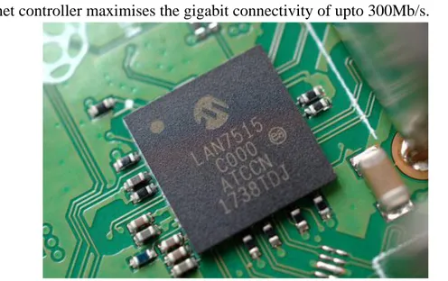
• Faster Ethernet(Gigabit via USB): Due to the use of single USB channel, the ethernet controller maximises the gigabit connectivity of upto 300Mb/s.
Figure 3. 3 Gigabit Ethernet Controller
• Dual-band 2.4GHz and 5GHz wireless LAN: The new dual-band radio module and antenna design improves the Pi 3B+’s connectivity compared to its previous models.
38
• Power over Ethernet(PoE) ready: An optional Power-over-Ethernet(POE) HAT module can power the Pi 3B+.
Figure 3. 5 Power-over-Ethernet HAT Module pins
• Power Management: A smoother power delivery is provided by the Power Management Inegrated Circuit(PMIC). It replaces the discrete components as compared to its previous models.
39
Raspberry Pi Model 3B+ Pinout with GPIO Functions
Figure 3. 7 Raspberry Pi Model 3B+ Pinout
Raspberry Pi Model 3B+ consists of 40-pin GPIO like previous pi models. GPIO stands for General Purpose Input Output pins, these pins are used to connect the Raspberry pi board to external input/output devices. A standard interface for connecting a single-board computer or a microprocessor to other devices is through these GPIO pins, the pins don’t have a specific function but they can be customized using the software.
40
Raspberry Pi 3B+ Power Pins
The model B+ board consists of two 5V pins, two 3V3 pins, and 9 Ground pins (0V), which are unconfigurable.
5V: The 5v pins are used to directly deliver the 5v supply coming from the mains adaptor. This pin is used to power up the Raspberry Pi, and it can also be used to power up other 5v devices.
3.3V: The 3v pin is used to provide a stable 3.3v supply to external components and to test LEDs.
GND: Ground pin is commonly referred to as GND. All the voltages are measured with respect to the GND voltage.
Input/Output pins
A GPIO pin set as Input reads the signal received by the Raspberry Pi, sent by the device connected to this pin. Any voltage between 1.8V and 3.3V is read as HIGH and voltage lower than 1.8V as LOW by the Raspberry Pi. In a case where an input voltage above 3.3V when connected to any of the GPIO pins can severely damage the circuitry of the board. A GPIO pin set as an output pin sends the voltage signal as high (3.3V) or low (0V). When this pin is set to HIGH, the voltage at the output is 3.3V and when set to LOW, the output voltage is 0V.
The GPIO pins can also perform a variety of specific functions listed below. PWM (pulse-width modulation) Pins on Model 3B+
• Hardware PWM is available on these pins: GPIO12, GPIO13, GPIO18 and GPIO19. • Software PWM is available on all pins.
SPI (Serial Peripheral Interface) Pins on Model 3B+
SPI (Serial Peripheral Interface) is another protocol used for master-slave communication. It is used by the Raspberry pi board to quickly communicate between one or more peripheral devices. Data is synchronized using a clock (SCLK at GPIO11) from the master (RPi) and the data is sent from the Pi to the SPI device using the MOSI (Master Out Slave In) pin. If the SPI device needs to communicate back to Raspberry Pi, then it will send data back using the MISO (Master In Slave Out) pin.
41
The Raspberry pi needs the following 5 pins to establish an SPI communication.
• GND: All GND pins from all the slave components and the Raspberry Pi 3 board should be connected.
• SCLK: Clock of the SPI. All SCLK pins should be connected.
• MOSI: It stands for Master Out Slave In. This pin is used to send data from the master to a slave.
• MISO: It stands for Master In Slave Out. This pin is used to receive data from a slave to the master.
• CE: It stands for Chip Enable, one CE pin per slave (or peripheral devices) should be connected in the circuit. By default, there are two CE pins but more CE pins from the other available GPIO pins can be configured.
SPI pins on Raspberry Pi Model 3B+
• SPI0: GPIO9 (MISO), GPIO10 (MOSI), GPIO11 (SCLK), GPIO8 (CE0), GPIO7 (CE1)
• SPI1: GPIO19 (MISO), GPIO20 (MOSI), GPIO21 (SCLK), GPIO18 (CE0), GPIO17 (CE1), GPIO16 (CE2)
I2C Pins on Raspberry Pi Model 3B+
I2C is used by the Raspberry Pi board to communicate with devices that are compatible with Inter-Integrated Circuit (a low-speed two-wire serial communication protocol). This communication standard requires master-slave roles between both the devices. I2C has two connections: SDA (Serial Data) and SCL (Serial Clock). They work by sending data to and using the SDA connection, and the speed of data transfer is controlled via the SCL pin.
• Data: (GPIO2), Clock (GPIO3)
• EEPROM Data: (GPIO0), EEPROM Clock (GPIO1) UART Pins on Raspberry Pi Model 3B+
Serial communication or the UART (Universal Asynchronous Receiver / Transmitter) pins provide a way to communicate between two microcontrollers or the computers. TX pin is used to transmit the serial data and RX pin is used to receive serial data coming from a different serial device.
• TX (GPIO14) • RX (GPIO15)
42
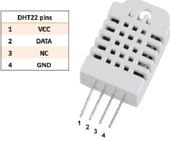
3.1.2 DHT22 AM2302 Digital Temperature and Humidity Sensor Module (Digital Output)
The AM2302 [23] is a wired version of the DHT22 embedded in a large plastic body. It is commonly used low-cost digital temperature and humidity sensor which uses a capacitive humidity sensor and a thermistor to measure the surrounding air. The output is a digital signal on the data pin (no analog input pins needed).
Figure 3. 8 DHT22 Pinout DHT22 Specifications
• power supply: 3.3V – 6V DC
• output signal: single bus
• sensing element: polymer humidity capacitor & DS18B20
• measuring range: humidity 0-100% RH / temperature -40°C – 125°C
• accuracy: humidity ±2% / temperature ±0.2°C
• sensing period: ~2s DHT22 Features
• Digital signal collecting technique and humidity sensing technology: It outputs a clean digital signal without the need for Analog to Digital converters and can be connected directly to one the GPIO pins of the Raspberry pi.
• Small and compact size • Low power consumption
• Long transmission distance(upto 20m)
43
3.1.3 Capacitive Soil Moisture Sensor v1.2 (Analog Output)
This capacitive soil moisture sensor v1.2 [24] measures soil moisture levels by capacitive sensing technique rather than resistive sensing like other types of moisture sensor. It is made of corrosion-resistant material and has a long service life.
Figure 3. 9 Capacitive Soil Moisture Sensor v1.2
Capacitive Soil Moisture Sensor v1.2 Specifications
• Operating Voltage: DC 3.3-5.5V • Output Voltage: DC 0-3.0V • Interface: PH2.0-3P
• Size: 99x16mm/3.9×0.63″
Capacitive Soil Moisture Sensor v1.2 Features
• It Supports 3-Pin Gravity Sensor interface.
• Analog output: It requires an Analog to Digital converter(A/D) while connecting to the Raspberry pi as pi lacks inbuilt A/D converter.
44
3.1.4 Resistive Soil Moisture Sensor (Analog Output)
The resistive soil moisture sensor [25] consists of two probes which are used to measure the volumetric content of water. The two probes allow the current to pass through the soil and then it gets the resistance value to measure the moisture value. When there is more water, the soil will conduct more electricity which means that there will be less resistance. Therefore, the moisture level will be higher. Dry soil conducts electricity poorly, so when there will be less water, then the soil will conduct less electricity which means that there will be more resistance. Therefore, the moisture level will be lower.
Figure 3. 10 Resistive Soil Moisture Sensor Resistive Soil Moisture Sensor Specifications
• Operating voltage: 3.3V~5V
• Panel PCB Dimension: Approx.3cm x 1.5cm
• Soil Probe Dimension: Approx. 6cm x 3cm
• Cable Length: Approx.21cm
• VCC: 3.3V-5V
• GND: GND
• DO: digital output interface (0 and 1)
• AO: analog output interface Resistive Soil Moisture Sensor Features
• Dual output mode, analog output more accurate
• A fixed bolt hole for easy installation
• With power indicator (red) and digital switching output indicator (green)
45
3.1.5 LED indoor grow lights
The LED indoor grow lights by Infinity [26] are commercially available but some minor design changes are applied because it is the primary actuator used with the switching relays for scheduled grow period. The plant grow light emits targeted wavelength lights that can be fully absorbed by plants to help accelerate growth. Ideal for all types of veg and flowering indoor plants in all stages of growth.
Figure 3. 11 Infinity full spectrum LED Plant grow lights LED Grow Lights Features
46
• Three Heads Improved Plant Light: Its design feature includes three goosenecks which solves the installation and inflexibility problem of traditional led plant light, but also provides a much larger coverage area than grow light clip with two arms. The coverage area with one head is approximately 24-27 inches depending on the height of the head location.
• Led Grow Light Full Spectrum: According to the type and light output (PAR) needed to support photosynthesis, this LED grow light with 3 color modes (red light, blue light and mixed light) and 5 brightness settings from 20% to 100%, which effectively complements the lack of natural sunlight and favored plant growth at all stages
. Figure 3. 13 LED Plant grow lights – illumination modes
• 360 degree adjustable: It is powered by USB or AC power socket (USB power supply included), it is portable and convenient to use at home or office. The gooseneck can be rotated 360 degrees which makes it easy to control the angle and distance between the grow light and the plants.
• Wide Usage: The led plant grow light is suitable for indoor plant seedlings, potted plants, leaf cuttings, greenhouse vegetables, etc, especially when the plant needs extra light when it rains, snows, it is dark in the covered, etc. Plant light help promote the growth, flowering and growth stages of plants.
47
3.1.6 MCP3008 Analog to Digital Converter IC
The MCP3008 10-bit Analog-to-Digital Converter (ADC) [27] combines high performance and low power consumption in a small package, making it ideal for embedded control applications. The MCP3008 features a successive approximation register (SAR) architecture and an industry-standard SPI serial interface, allowing 10-bit ADC capability to be added to any PIC® microcontroller. The MCP3008 features 200k samples/second, 8 input channels, low power consumption (5nA typical standby, 425µA typical active), and is available in 16-pin PDIP and SOIC packages. Applications for the MCP3008 include data acquisition, instrumentation and measurement, multi-channel data loggers, industrial PCs, motor control, robotics, industrial automation, smart sensors, portable instrumentation and home medical appliances.
Figure 3. 14 MCP3008 Analog to Digital Converter IC
MCP3008 A/D Converter IC Pinout
48
Pin Number Pin Name Description
1,2,3,4,5,6,7,8 Analog Input Channels
These are the 8 Input pins, to which the analog voltage which must be measured is provided.
9 Digital Ground Connected to the Ground of the circuit
10 Chip Select /
Shutdown (CS`/SHDN)
This pin is connected to GPIO pin or MCU for turning on or off the IC
11 Serial Data In
(DIN)
Used for SPI communication
12 Serial Data Out
(DOUT)
Used for SPI communication
13 Serial Clock (CLK) Used to provide clock signal for SPI communication
14 Analog Ground Connected to Ground of the reference voltage
15 Reference Voltage
(VREF)
Connected to reference voltage for ADC Conversion
Table 3. 1 MCP3008 Analog to Digital Converter IC – Pinout MCP3008 A/D Converter IC Specifications
• Max Sample Rate(ksamples/sec): 200 • Max Supply Current(µA): 500
• Input Type: Single-ended • Number of Input channels: 8 • Resolution(bits): 10
• Interface: SPI
• Temperature Range(°C): -40 to +85°C • Input Voltage Range(V): 0 to 5.5V MCP3008 A/D Converter IC Features
• Analog inputs programmable as single-ended or pseudo-differential pairs • On-chip sample and hold
• SPI serial interface (modes 0,0 and 1,1) • Low power CMOS technology
• 5 nA typical standby current, 2 µA max. • 500 µA max. active current at 5V