DEPARTMENT OF MECHANICAL ENGINEERING
A New Damage Detection Technique
Cheng Liangliang
Ph.D. Thesis in Mechanical Engineering
XXIX Cycle
POLITECNICO DI MILANO
DEPARTMENT OF MECHANICAL ENGINEERING DOCTORAL PROGRAMME IN MECHANICAL ENGINEERING
A New Damage Detection Technique
Doctoral Dissertation of:Cheng Liangliang
Supervisors:
Prof. Cigada Alfredo Prof. Busca Giorgio
Tutor:
Prof. Pennachi Paolo Emilio Lino Maria
Abstract
Many infrastructures and mechanical structures are inevitable to suffer damage along with aging, which has drawn a lot of attention during the research of last decades in terms of the damage localization and quantification of engineering structures for health evaluation. Damage identification based on vibration-based data has been developed rapidly, since the change of physical structure naturally causes a change of system property such as natural frequency, modal damping and mode shape. There exists a variety of vibration-based methodologies for damage detection: by means of the change of natural frequency, the change of mode shape, the change of frequency response function and the change of transmissibility function, and so on. Among these methodologies, measuring the change of transmissibility function is preferable since it not only has a better sensitivity to the damage but also none prior information of the system loading is required.
Transmissibility function as one of the most popular methods widely applied for identifying damage. Moreover, it is traditionally defined as response spectrum ratio between two degrees of freedom. During the recent decades, more damage indicators based on transmissibility function have been proposed and their results of damage identification have proved the excellent performance of this approach in terms of the sensitivity than the classical frequency response function (FRF). The author also points out the significance of poles and zeros to localize damage in the dynamic system. More recently, it has been proved that the value of transmissibility function converges to the mode shape ratio when frequency bandwidth is restricted to the system’s poles.
The convenience and effectiveness of using transmissibility in practice is the basis of making it selected as the main research object in this work. A new conception, namely strain transmissibility function, has been proposed in this study due to the fact that strain is more sensitive regarding to damage in comparison with displacement, which could be proved through the related sensitivity analysis. In addition, the
Especially when dynamic test is performed on large structures such as bridges, tunnels and buildings, it is extremely difficult to reach the target of full coverage on the objects. Also, usually a large number of sensors are need and then the idea is impracticable mainly for economic reasons. Fortunately, distributed fiber optics techniques have kept developing rather maturely and they have been applied into various domains which can measure continuously strain and temperature along the structure layout. During the validation of the feasibility of the proposed new conception and approach, a series of simulation studies and the related experiments based on distributed fiber optics have been carried out.
However, many researchers mainly concentrate on linear damage case where damage can be considered as the linear reduction of mass and stiffness, apparently, their methodology is unable to detect the change caused by the nonlinear damage. Damage scenarios in engineering structures are manifested as nonlinear behaviours in many cases, which could be deemed as the potential security hazard. Certain types of damage in MDOF systems create a significant nonlinear change instead of a linear one, such as breathing crack (Bilinear stiffness), post-buckled structures (Duffing nonlinearity) and rattling joints (The system with discontinuity), etc. Therefore, the study on nonlinear damage identification is of great importance.
Another part of this study focuses on nonlinear damage identification based on the conception of nonlinear output frequency response function (NOFRF). The highlight of this work is the extension of the NOFRF approach to the general input condition and corresponding simulation on a MDOF system clearly demonstrates its availability. In particular, this work also discovers and proves the relationship between NOFRF-based transmissibility function and Output-NOFRF-based transmissibility function under general input condition, which offers a more convenient and reliable strategy for detecting and localizing damaged components, on account of various damaged scenarios, including existence of single damaged component and multiple damaged components. In addition, various loading scenarios are taken into consideration as well, including single-point loading, multiple-point loading and distributed uniformed loading.
Declaration
The author hereby declares that this dissertation is a record of work carried out in the Department of Mechanical Engineering at Politecnico di Milano during the period of October 2013 to April 2017. This dissertation is original in content except where otherwise stated.
Cheng Liangliang
Acknowledgements
First of all, I would like to express my deepest thanks to my supervisor Prof. Alfredo Cigada and Giorgio Busca for their excellent guidance and encouragement to provide me sufficient support throughout these years. It was honored to be one of their students.
I am sincerely grateful to the Prof. Ziqiang Lang, who has offered me a great opportunity research period in University of Sheffield. Even if I just spent few months there, it made a significant enhancement on my research work.
Special thanks go to Prof. Michele Gasparetto, Stefano Manzoni, Giovanni Moschioni, Marco Tarabini, Emanuele Zappa, who provided me a lot of help during my research activities.
I would like to thank to my friend, Yunpeng Zhu, in University of Sheffield, who often discussed with me and provided me useful suggestions when I was confronted with difficulties in my research.
I would like to thank my intimate colleagues, Alessio Datteo, Silvio Giancola, Rui Liu, Ambra Vandone, Marta Berardengo, Alberto Lavatelli and Ali Siami, who have shared with the wonderful research period in the research group of measurement.
I am grateful to my friends, Wenshan Fang, Peixue, Menglu Liao, Fan Yang and Huilong Yu, whom I enjoyed my spare time together.
Thanks to the all the member staff in the experimental lab (C4), who very kindly helped me with my experiment setups, and special thanks go to the administrative and support staff, Marcella Netti and Silvia Barattieri.
In the last but not the least, I would like to say thank you to my family, my father, my mother and my sister. They keep giving me the encouragement and home-support during these years.
Contents
Abstract ... 2 Declaration ... III Acknowledgements ... IV CHAPTER 1 ... 1 1.1 Overview ... 11.2 Structural Health Monitoring ... 1
1.2.1 The conception of SHM ... 2
1.2.2 Model-based and data-driven approach ... 3
1.2.3 Applications of SHM system ... 5
1.3 Vibration-based structural damage identification ... 6
1.3.1 Based on the change of natural frequencies[32-37] ... 7
1.3.2 Based on the change of mode shapes[38-45] ... 7
1.3.3 Based on the change of flexibility[46-54] ... 8
1.3.4 Based on the change of FRF[55-59] ... 8
1.3.5 Based on the change of transmissibility function[60-69] 9 1.4 Fiber optics ... 10
1.4.1 Fiber optics sensing technologies... 11
1.4.2 SHM applications on distributed fiber optics ... 23
1.5 Research objective and scope ... 25
1.6 Outline of the thesis ... 27
CHAPTER 2 ... 28
2.1 Overview ... 28
2.2 Traditional transmissibility and strain transmissibility ... 29
2.3 Damage indicators ... 31
2.4 Strain transmissibility sensitivity analysis ... 32
2.5 Simulation study ... 34
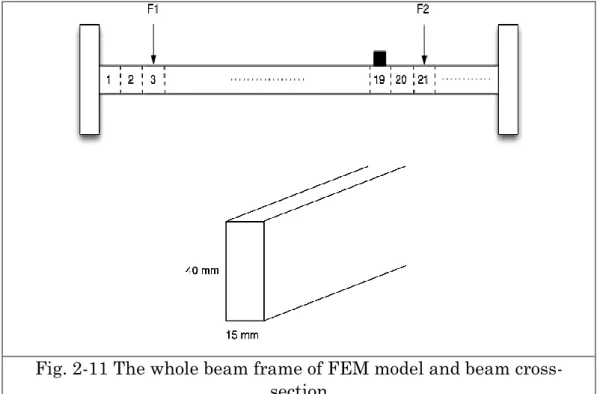
2.5.1 FEM modelling of the beam ... 35
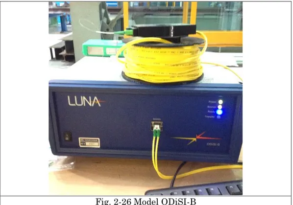
2.6.1 Brief introduction of ODiSI-B ... 46
2.6.2 Experimental setup description of the beam ... 49
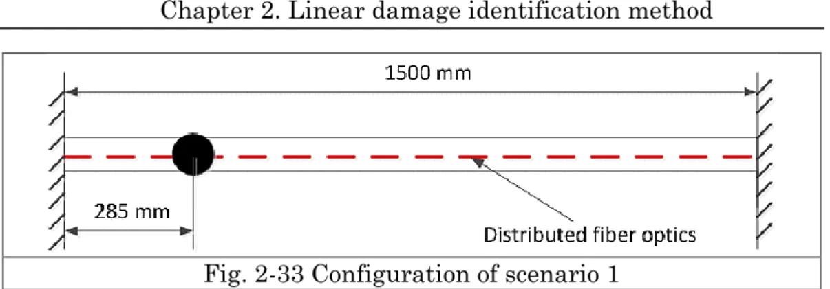
2.6.3 Damage identification of experimental beam ... 51
2.6.4 Aliasing issue of distributed fiber optics ... 57
2.7 Conclusion ... 60
CHAPTER 3 ... 62
3.1 Overview ... 62
3.2 Nonlinear output frequency response function ... 63
3.2.1 Conception of NOFRFs ... 63
3.2.2 Estimation of NOFRFs ... 66
3.3 Transmissibility of MDOF nonlinear structural system under general input ... 68
3.3.1 MDOF Nonlinear structural system description ... 68
3.3.2 Output frequency range of MDOF Nonlinear structural systems under general input ... 70
3.3.3 NOFRF-based transmissibility of MDOF Nonlinear structural systems under general input ... 73
3.3.4 Output-based transmissibility of MDOF Nonlinear structural systems under general input ... 88
3.3.5 Some important properties of NOFRF-based transmissibility and Output-based transmissibility of nonlinear MDOF system under general input ... 90
3.3.6 Damage detection and localization method ... 98
3.3.7 Effect of boundary conditions ... 110
3.3.8 Simulation study ... 112 3.3.9 Experimental study ... 135 3.4 Conclusion ... 169 CHAPTER 4 ... 171 4.1 Conclusions ... 171 4.2 Contribution to knowledge ... 173
CHAPTER
1
Introduction
1.1 Overview
This chapter deals with a systematic literature review about structural damage identification concerning the field of Structural Health Monitoring (SHM). Due to the continuously increasing demand on damage identification for engineering infrastructures, the methods about vibration-based structural damage identification have drawn the attentions of many researchers. A brief review on above-mentioned methods is given. Afterwards, on the account of the rapid development of distributed fiber optics technology that show many distinct advantages, the potentials applied to SHM have been keeping investigated. A literature review of distributed fiber optics is presented later on, which involves the recent engineering applications. Finally, it clarifies the research objectives and the novel contributions of this thesis.
1.2 Structural Health Monitoring
The security issues of aerospace, civil and mechanical engineering infrastructures are increasingly catching the sight of many researches, because most of civil, mechanical and aerospace structures are
fatigue and corrosion which makes SHM become strongly motivated. Damage is defined as changes of material or geometric characteristics, also including changes of boundary conditions and system connectivity. Loads of available effective non-destructive tools and researches have been emerged over the past 30 years, and damage identification becomes the coral basis of SHM.
1.2.1 The conception of SHM
The process of implementing a damage identification strategy for aerospace, civil and mechanical engineering infrastructure is referred to as structural health monitoring (SHM)[1]. The basic idea is to infer changes in structural properties and predict structural damage by measuring the response of the structure before and after abnormal loads, or to detect long-term structural degradation through continuous monitoring. For civil engineering structures, the SHM system can monitor structural damage under earthquake or explosion, or monitor health status of the structures for a long term under the surrounding environment and human activities. This information can provide an important reference for the structural safety assessment and can also be used for the maintenance of the structures and the assessment of their remaining life.
SHM system generally consists of four main subsystems[2]: 1. Sensor system; 2. Signal acquisition and processing system; 3. Signal communication and transmission system; 4. Signal analysis and monitoring system.
SHM technology is based on the measurement results from the same location of structures at different time stages to identify the health state of the structures, so historical data is critical, and the accuracy of recognition depends strongly on the sensors and the interpretation algorithms. It can be said, structural health monitoring is likely to be widely used offline, static, passive damage monitoring, into online, dynamic, real-time monitoring and control. However, current SHM systems to ensure the safety operation of bridges as the goal still need to be developed compared to the anticipation due to the main reason that the current SHM systems are devoting at damage detection after the existence of damage rather than damage prognosis. Therefore, damage
detection and damage prognosis can be composed of two main research topics of SHM and there is inherent difference between them: Damage detection is carried out based on the deterministic monitoring data[3-5], while damage prognosis is to predict the possible damage in the future based on historical monitoring data. The main purpose of damage prognosis is to remind the owner taking necessary technical measures to reduce the structural damage or prevent possible catastrophic damage before damage occurrence[6-8].
1.2.2 Model-based and data-driven approach
Due to the higher performance and increasing demand for structural health monitoring system, damage detection has become more and more important with aiming to increase the safety and reliability of the structures. Early fault diagnosis can help to avoid abnormal events and reduce the loss of productivity, which in turn can be beneficial to avoid the main system failures and disasters. Therefore, fault diagnosis is a major research topic, attracted by industry practitioners and academic researchers. There is a lot of literature about the process of fault diagnosis from analysis methods to artificial intelligence and statistical methods. From the viewpoint of modeling, some methods need precise process models, semi quantitative or qualitative models. On the other hand, some methods don’t depend on any models, only rely on the time history data. The fault diagnosis methods from [9], [10] and [11] can be required is divided into two categories, model-based and data-driven methods regarding to the prior process knowledge.
Model-based methods can be divided into qualitative[12, 13] and quantitative[9, 10, 14, 15] methods, given the provided prior knowledge, which is usually developed based on some basic understanding of the process of physics. In the quantitative model, the understanding of this model can be read from the relationship between system input and output function. As for qualitative model, qualitative functions can be used to describe the system. Data-driven methods take the availability of a large amount of time history data, which can be converted and presented as a priori knowledge to different ways of diagnosis system. Feature extraction can be made from those time history data in order to diagnose faults. The feature extraction process can be defined as quantitative or qualitative methods as well. In the quantitative feature
statistical way.
Model-based method is mainly discussed in the finite element model development. After the initial development of the finite element model, the experimental data is used to update the dynamic characteristics of system matrix (mass, stiffness and damping), to make the model more accurate which is able to represent the experimental structure. Then making use of the measured structure data collected to perform damage identification through the inverse problem[16].
Data-driven approach, as another hot topic of damage detection, has been continuously developing. The data-driven approaches do not need prior knowledge of the process, but aim at investigating the hidden information in the data through various data analysis and processing methods based on the historical process data, and obtaining the different data characteristic patterns under the normal operational condition and the damaged situation, thereby determining the operational status of the process. Because the data-driven method only relies on the time history data, it is general-purpose and suitable for the fault detection and diagnosis of various structures and devices. In the meantime, through the various data processing and analysis methods (such as multivariate statistical methods, cluster analysis, spectral analysis, wavelet analysis, etc.) to extract the feature from the data in order to identify the damage. Data-driven can be categorized into linear regression method[17], artificial neural network method[18-20], support vector machine method[21-23], fuzzy modeling methods[24-26]. The main advantage of data-driven methods is that it does not need to set up a complex mathematical model, which reduces the workload of theory and calculation, and avoids the error caused by modeling. And high-dimensional data can be condensed into low-high-dimensional data to be analyzed[27]. But from another point of view, it is too dependent on the accuracy of vibration measurement signals. Measurement error and measurement noise will have a great impact on the recognition results. The most critical point is that data-driven methods are not directly related to the physical parameters of the structure itself, so it is difficult to achieve quantitative identification of structural damage.
1.2.3 Applications of SHM system
Many infrastructures like towers, high-rise buildings and bridge structures must have been regularly assessed in order to achieve safety, maintenance, and obtain economic benefits. The structure maintenance and monitoring of the condition of the structure becomes a great challenge. The structural health monitoring (SHM) in recent decades in civil engineering, aerospace engineering, machinery and many other fields has aroused great concern. For an example, a variety of sensors have been installed in Akashi Kaikyo Bridge[28], as the world longest suspension bridge, in order to confirm the design assumptions and relevant parameter values of the bridge under strong wind and earthquake. Sensor devices like anemometers which are aiming to determine the wind characteristics of the bridge, seismometers, accelerometers are used to verity the dynamic behavior under earthquake, velocity gauges, girder edge displacement gauges, tuned mass damper (TMD) displacement gauges, thermometers and GPS. Three bridges of the Korea Expressway Corporation in Korea[29] have been chosen as a Korea-US joint research, various smart sensors and sensor configuration have been adopted such as piezoelectric sensors, wireless sensors, and also vision-based monitoring system, attempting to validate their independent research and development on the smart sensors, sensing monitoring system and data processing algorithms. Take another example, the Canton Tower in Guangzhou[30], China, with a total height of 600m, is a circular gradient grid structure. SHM system has been applied into this tower, with implementing 800 sensors to cover the complete tower itself, which contains 6 modules: Sensory system, Signal acquisition and transmission system, Signal processing and control system, Data management system and Maintenance system. In order to employ the SHM system, ambient vibration under different conditional stages has been carried out for a long term monitoring. FEM-based mode update has been accomplished by comparing the experimental modal analysis. Also the relative modal parameters of the tower have been successfully identified.
identification
With the advancement of science and technology, modern space structure is inclined to be large-scale and complexed due to the demand for industrial development, as well as the future development of mankind. However, these structures will be damaged under some environmental conditions which will change the characteristics of the structure, and lead to a greater structural damage accumulation. And eventually it will bring about sudden failure of the structure, so that the safety of the structure is being threatened. Therefore, structural damage identification has become the focus of attention of scholars all over the world. Especially, structural damage diagnosis based on structural vibration response and system dynamic characteristic parameters has become a focus of research in recent decades. And structural damage identification based on non-destructive testing methods is a current hot and difficult research. Nowadays non-destructive identification technology is widely used in the aerospace industry, power plant equipment, construction, metallurgy and machinery manufacturing etc. The basic idea is: damage can cause changes in the structures of the physical parameters (mass, stiffness, etc.), the modal parameters of the structures (modal frequencies, mode shapes, modal damping, etc.) will change accordingly, thus damage can be determined based on these variables.
According to different technical levels, the damage identification and quality assessment of engineering structures can be divided into four levels[31]:
1) Whether the structure is expected to be damaged; 2) To determine the location of damage;
3) To determine the degree of damage;
4) Life expectancy after the structural damage.
The following part demonstrates various vibration-based methods on damage identification briefly.
1.3.1 Based on the change of natural frequencies[32-37]
Natural frequency is a function of structural stiffness and mass. An occurrence of damage to the structures will lead to a change of natural frequencies. For the actual engineering structures, the natural frequencies are easy to be measured and not related with the measurement position. The error of the frequency measurement is smaller than that of the vibration mode and the damping measurement. But it is not enough to provide sufficient information for damage identification. The advantage of using natural frequencies to detect damage is that the natural frequencies are easy to be obtained and the measurement accuracy is high. But natural frequencies of structural sometimes are not very sensitive to early damage, usually only existence of damage can be found, and the damage location cannot be determined due to that a damage at different locations can cause the same amount of frequency change. Some investigations have been published in relative articles, which claimed that damage identification based on natural frequencies can be merely feasible for some particular structures. The application on complexed structures is still a challenge and it needs to be developed.
1.3.2 Based on the change of mode shapes[38-45]
Structural damage will result in changes in mode shape, and mode shape contains the location information, hence the methods based on the vibration mode shape can not only identify the damage but locate the damage. The basic idea is to identify the mode shape before and after damage, and compare the difference for each measurement point which is capable to recognize and localize the damage. In addition, MAC and COMAC criteria could be useful damage indicators as well. Apart from the change of mode shape, the slope and curvature of mode shape could be used to damage identification based on the fact that the small perturbation caused by the damage on the mode shape will be amplified, resulting in a significant change in the slope and the curvature of the mode shape. Therefore, the slope and the curvature of the mode shape is more sensitive in terms of damage compared to mode shape itself. However, the measurement error of eigenvectors is rather larger than that of eigenvalues. The effectiveness of the mode shape based method
modes is related to the quality of the test data and the number of measurement points. And the quality of test data relies on the instruments and the corresponding methods Generally the accelerometers and other traditional sensors have been applied into acquire the response, also there emerges some advanced test methods, such as laser Doppler vibrometer, Spot pattern interferometer, fiber optics, etc.
1.3.3 Based on the change of flexibility[46-54]
Under the condition that the modal normalization, the flexibility matrix is a function of the reciprocal of the frequency and the mode shape. As the frequency increases, the reciprocal effects of the high frequency in the compliance matrix are negligible, so that a matrix with good accuracy can be obtained as long as the first few lower order modal parameters and frequencies are measured. The largest element in each column of the difference matrix is obtained from the difference matrix of the two flexibility matrixes before and after damage, and the position of the damage can be found by checking the largest element in each column. Pandey and Biswas proposed a structure damage method based on flexibility matrix difference, and it is shown that the flexibility matrix difference is quite effective in locating and identifying the damage. Toksoy and Aktan[52] proposed a method to evaluate bridge condition based on modal flexibility obtained from measured processing data, and it has been applied into a three-span high way bridge. Moreover, Li Yongmei et al.[53] proposed a structure damage identification method based on flexibility difference curvature, and it is proved that only low modal orders are effective enough to be considered into assess the structural health conditions. Catbas et al.[54] further extended the application of modal flexibility and derived a practical approach to obtain modal flexibility from real modal tests data.
1.3.4 Based on the change of FRF[55-59]
When natural frequency or mode shape are considered as the basis for damage identification, the primary step is to identify the natural frequencies or mode shapes of the structure by means of modal identification methods, which is time-consuming and introduces
parameter identification errors. And even, when the damage occurs near the node of a certain mode, the changes of modal parameters, such as the natural frequency and mode shape, are very small before and after the structural damage, thus the structural damage cannot be identified based on those modal parameters. Therefore, using frequency response function considered as raw data without data post-processing could be a greater approach for damage detection.
Based on the similar assumption of detecting the damage in accordance with the greatest change of mode shape, a new conception called “operational mode shape” could be utilized and applied into the damage detection, through finding the greatest change of operational mode shape during the selected frequency range. There are various existing methods for damage detection, which are based on FRF-operational mode shape, FRF-operational mode shape slope, FRF-operational mode shape curvature and its square. An issue needs to be noted, true damage location might be masked when a broader frequency range is considered into the selection for damage indicator calculation, due to the reason that the differences between undamaged and damaged frequency response functions where are near around resonances and anti-resonances are going to be larger, which could cover the true damage location if a false damage location is identified under those frequencies. Therefore, a new conception of occurrence has been put forward in order to lower the possibility of identifying false damage locations, based on the idea that the location can be found where the maximum difference between undamaged and damaged frequency response functions under each frequency line. And occurrence will be counted and summed so as to locate the damage.
1.3.5 Based on the change of transmissibility function[60-69]
Transmissibility function as one of most popular methods widely applied for identifying damage has been proposed firstly in[60]. And it is traditionally defined as response spectrum ratio between two degrees of freedom. During the recent decades, more damage indicators based on transmissibility function have been proposed[60-62] and demonstrated their excellent performance in terms of damage identification, owing to the fact that transmissibility is more sensitive to local damage compared to FRF, which has been discussed in[65], and it points out the
More recently, it has proved that the value of transmissibility function converges to the mode shape ratio when frequency bandwidth is restricted to the system’s poles. Even though the methods based on transmissibility don’t need any mathematical model or a priori knowledge, and can effectively identify early structural damage, the number and position of the measurement points have a great influence on the damage identification accuracy[70].
However, many researches mainly concentrate on linear damage case where damage can be considered as the linear reduction of mass and stiffness, and it has been proved to be insensitive in terms of nonlinear damage. Few researches concentrate on the nonlinear damage situation based on the conception of transmissibility so far. It is worthy to mention that Timothy J. Johnson[65] introduced nonlinear component in MDOF system by utilizing cubic nonlinear stiffness on the spring. Lang[66] firstly proposed the damage index for detecting nonlinear component based on nonlinear output frequency response function under harmonic excitation, which has been proved effectively by mathematical derivation and relevant numerical simulations. Zhao and Lang[69] have recently proposed a new method based on transmissibility at super-harmonic frequencies for identifying nonlinear components, that does not need the identification of NOFRFs, in other words, input signal doesn’t need to be measurable.
1.4 Fiber optics
Fiber optic transmission and sensing are two important areas of fiber technology[71]. Fiber-optic sensor is widely used because of its rapid development and application. Fiber-optic sensor has strong potentiality of anti-electromagnetic interference, high sensitivity, good electrical insulation, safe and reliable, corrosion-resistant. It can be applied in many fields such as industry, agriculture, biomedicine, national defense and so on, which could be reckoned as an innovational measurement placement instead of the traditional detection technology and instrumentation.
Its enhancement on measurement technology and instrumentation can be reflected as the following aspects[71-74]: (1) High sensitivity. Because
light is an electromagnetic wave with a very short wavelength, its optical length could be obtained through its light phase. The optical fiber interferometer, for example, because the diameter of fiber optics is very small, when the fiber is subject to a small mechanical external force or temperature changes, its optical length will change, that causes a large phase change. (2) Anti-electromagnetic interference, electrical insulation, corrosion resistance, intrinsically safe. As the optical fiber sensor is the use of optical transmission of information, also optical fiber is electrically insulated, corrosion-resistant transmission medium, and safe and reliable, which makes it effectively use for strong electromagnetic interference, flammable, explosive and other harsh environments. (3) High measurement speed. Light is the fastest and can transmit two-dimensional information, it can be used for high-speed measurements. Signal analysis of radar requires a very high detection rate, the application of electronic methods is difficult to achieve, while the use of high-speed spectrum analysis based on light diffraction phenomenon can be resolved. (4) Huge information capacity. In addition, fiber optic sensor also has a light weight, small size, able-curved, wide range of objects, reusability, and low cost. The optical fiber sensor has so many advantages, making its application is very extensive, involving petrochemical, power, medical, civil engineering and many other fields. So it will have a huge role in promoting on the development of science and technology, industrial and agricultural production and national defense construction.
1.4.1 Fiber optics sensing technologies
A typical fiber optic transmission configuration is shown in Fig. 1-1, which mainly contains five components and operate the process of transmitting the information.
1) A converter should be used in order to transform electric signal into a signal which could be recognized by light source.
2) A light emitter should be needed to transmit the light into fiber optics.
3) The light signal should go through the fiber optic until it reaches the end of the fiber optics.
4) It is a must to have a light detector, which is able to detect the light signal and reconvert the light signal into electric signal at the end of
5) A converter is needed to reconvert the light signal back to the electric signal and complete the whole transmission process.
Fig. 1-1 Configuration of a typical fiber optics transmission process The basic composition of a cross-sectional typical fiber optics is shown in Fig. 1-2, which are the core, the cladding and the coating. The optic fibers are usually made by transparent materials such as glass, and it is the core which surrounded by another cylindrical layer called cladding. And the outer layer is aiming to protect the fiber and provide stronger durability. Generally speaking, the diameter of the optical fiber is rather thin, like 0.1-0.3 mm. However, these parameters are not fixed and able to be adjusted according to the particular demands.
Core
Cladding
Coating
Fig. 1-2 The basic composition of a typical fiber optics
There are several existing fiber optics sensing technologies in recent days, and they have been already applied into commercial purpose. In
Signal to light converter Light emitter Fiber optics Light detector Light to signal converter
general, they can be classified into three types: grating-based sensors, distributed sensors and interferometric sensors[75]. There are loads of fiber optics applied into real industrial engineering field. An overview of the types of fiber optics based on the sensing technologies has been listed in Fig. 1-3. Fiber Optic Sensors Grating-based Sensors Distributed Sensors Interferometric Sensors Fiber Bragging Grating Sensors Long Period Grating Sensors Tilted Fiber Bragging Grating Sensors Rayleigh Distributed Sensors Raman Distributed Sensors Brilliouin Distributed Sensors SOFO Sensors Mach-Zehnder Sensors Fabry-Perot Sensors Sagnac Sensors
Fig. 1-3 A list of the types of fiber optics (adapted from [75])
1.4.1.1 Grating-based sensors
Fiber Bragg Grating sensor is a nonlinear optical fiber sensor of wavelength modulation type[76]. It has been considered as the most mature fiber optics sensor, which have been already applied into many
industrial fields. A basic functional principle of FBG can be found in Fig. 1-4.
Fig. 1-4 Functional principle of FBG sensor (adapted from [75]) The fiber Bragg grating sensor is one of the most widely used fiber optic sensor, which can change the wavelength of the reflected light according to the change of ambient temperature and / or strain[77, 78]. Fiber Bragg Grating is based on holographic interference or phase mask method, which makes a small piece of light-sensitive optical fiber exposed to a period distribution of light intensity. Thus the optical refractive index of the optical fiber is permanently changed depending on the intensity of the light to be irradiated. This method of periodic changes in refractive index of light is called Fiber Bragg Grating.
When a beam of light with a broad spectrum is propagated to the fiber Bragg grating, each fraction of the fiber after the change in refractive index reflects only a specific wavelength of light, called the Bragg wavelength, as shown in the following equation(1-1). This characteristic makes the fiber Bragg grating reflect only a specific wavelength of light, and other wavelengths of light will be spread.
2
b n
(1-1)
In equation, is the Bragg wavelength, b nis the effective refractive
index of fiber core and is the interval between gratings is called the grating period.
Fig. 1-5 A perspective view of a fiber Bragg grating
Strain and temperature will affect the effective refractive index n and the grating period Λ of fiber Bragg grating, which results in the change of grating reflected light wavelength. The change of the reflection wavelength of fiber Bragg grating with strain and temperature can be approximated by the relation in equation(1-2):
0 1 pe n T (1-2)In equation, where is the change of reflected wavelength and is 0 the initial reflected wavelength.
The term
1 pe
indicates the effect of strain change on the reflectionwavelength. Where p is the strain optical sensitivity coefficient, and ε e is the change of strain effected by grating. The term
n
Tindicates the effect of temperature change on the wavelength. Where is the thermal expansion coefficient and is the temperature optical n sensitivity coefficient. The coefficient reflects the optical refractive index due to temperature changes and the coefficient reflects the n same temperature changes caused by the grating cycle change.
Because the fiber Bragg grating will be affected by strain and temperature changes at the same time, it is necessary to consider both of these factors during the calculation of reflection wavelength changes, but also to analyze them separately. When performing temperature measurements, the fiber Bragg grating must be kept completely free of strain. You can use the FBG temperature sensor that is specifically packaged for this purpose. This kind of sensor ensures that the properties of the fiber Bragg grating inside the package are not coupled
case, the thermal expansion coefficient of the glass is usually negligible in practical use. Therefore, the change in the reflection wavelength due to the temperature change can be mainly determined by the temperature optical sensitivity coefficient of the optical fiber. n Fiber Bragg grating strain gauges are more complicated in some way because temperature and strain affect both the reflected wavelengths of the sensor. In order to perform the measurements correctly, the influence of the temperature on the fiber Bragg grating must be compensated during the test. In order to achieve this compensation, you can use a FBG strain sensor with good thermal contact FBG temperature sensor to complete. After obtaining the test results, simply subtracting the wavelength change measured by the FBG temperature sensor from the wavelength change measured by the FBG strain sensor can eliminate the second expression to the right of the plus sign from equation(1-2) and this compensates for the effect of temperature changes during strain tests.
In addition to be used widely in strain and temperature monitoring applications, a new signal detection technology has been discovered based on acoustic or ultrasonic signals[79, 80], which could be effectively applied into structural health monitoring. The coral change for this technology is traditional PZT sensors have been placed by FBG sensors to collect acoustic or ultrasonic signals, which makes wring issue more simple. Full scale monitoring is on high demand for large infrastructures, FBG sensors are capable to meet this need by using the multiplexing technology.
1.4.1.2 Distributed sensors
Distributed fiber-optic sensor is arranged along the field, the field distribution and time-varying information can be measured and monitored by using the unique detection technology along the fiber transmission path along. They can provide a real distributed way to monitor the structures along the entire fiber. Due to the large amount of information obtained at the same time, the cost of unit information is greatly reduced, so that a high cost performance can be obtained. It is a very promising sensor which can be competitive with point sensing
sensors, so in recent years more and more attention has been caught on the research of distributed fiber optics sensors. The basic principle of distributed fiber optics is shown in Fig. 1-1.
Light Circuit Light Coupler Measured field Detector
Distributed fiber optics
Fig. 1-6 Basic principle of distributed fiber optics
There are three main classification based on two different sensing technologies: OTDR, OFDR and POTDR, namely optical time domain reflectometry, optical frequency domain reflectometry and polarization optical time domain reflectometry respectively. Optical time domain reflectometry technology emerged at the beginning of 1980, aiming to test the optical cables for the use of telecommunications. In the OTDR technique[75, 81-83], a short light pulse is emitted into the fiber, and then the photodetector processes the amount of light which is backscattered as the beam propagates along the fiber.
Generally speaking, light transmission in the fiber will occur three types of scattering, including Rayleigh scattering caused by the changes in the refractive index of fiber, optical phonon-induced Raman scattering, and Brillouin scattering caused by acoustic phonon[84]. Rayleigh scattering is an inherent property of optical fibers. When light waves propagate during the fiber, they encounter linear scattering due to the random fluctuation of refractive index n of the fiber core. Brillouin scattering is the result of the interaction of incident light with acoustic or propagating
constant velocity (and with a certain frequency). Therefore, the Brillouin scattering can be regarded as the scattering of the incident light on the moving grating, and the Doppler effect makes the frequency of the scattered light different from that of the incident light. When the scattered light, incident light and pressure wave under specific frequency meet the phase matching conditions (for grating, is corresponding to meet the Bragg (Bragg diffraction conditions)), the scattered light intensity is the maximum under this frequency.
Fig. 1-7 Backscattering spectrum (adapted from [84])
Raman scattering is the phenomenon that a photon of the incident light is scattered into another low-frequency photon by an acoustical photon, and the acoustical phonon completes the transition between its two vibrational states. Raman scattering depends on the temperature of the fiber which has been found in[85, 86] so as to develop various unique technique of measurement. Raman scattered light contains Stokes light and anti-Stokes light. As shown in Fig. 1-7, Rayleigh scattering does not change its wavelength, while Raman scattering and Brillouin scattering are the information carried by the inelastic scattering of light and matter. And their scattering wavelength is shifted with respect to the incident wavelength.
And it is worthy to mention that Rayleigh scattering, as a quasi-elastic or linear phenomenon, mostly relies on any external physical field. And
Rayleigh-based distributed fiber optics is used to measure propagation effects, which contains attenuation and gain, phase interference and polarization variation. However, Raman and Brillouin-based distributed fiber optics are influenced by the propagation effects as well, but it can be neglected due to the direct relation with the measurement parameters.
Table. 1-1 concludes the characteristics and applications of the distributed fiber optics based on OTDR technology.
Table. 1-1 The characteristics and applications of the distributed fiber optics based on OTDR technology
Technology Advantages Shortcomings Main
applications
OTDR
Continuously shows the variation of the loss of the
entire fiber line relative to the distance. Non-destructive measurement, multi-function, easy to use There is always a blind spot. The attenuation values
measured at both ends of the fiber are
usually different, usually the average
value is taken. For the detection of fiber damage points BOTDR For a single distribution of the measurement parameters have a high accuracy and spatial Because the Brillouin frequency
shift is very small, and its line width is
very narrow, which requires the laser
has a very high frequency stability
Stress and temperature
(about kHz) adjustable line width, the optical filter also has high
requirements. The system is complex and expensive to manufacture and
use. The current focus is on temperature and stress sensing. BOTDA High precision and spatial resolution, dynamic range, high accuracy
The system is more complex, pump laser and detection
laser must be placed on both ends
of the measured fiber, the practical application contains certain difficulties; It cannot be measured due to the existence of damaged sensing points; Application conditions are limited; Stress and temperature changes caused by more difficult to distinguish Stress and temperature monitoring
relative sensitivity and temperature measurement accuracy, expand the system's functionality and reduce costs High requirement on light source.
Distributed fiber optics technologies based on OFDR mainly contains three different types: OFDR (based on Rayleigh scattering), ROFDR (based on Raman scattering) and BOFDA (based on Brillouin scattering). Optical frequency domain reflection (OFDR) systems[87-92] has drawn the attention from many research institutes with aiming to obtain the goal of short spatial resolutions and cost-effectiveness. In order to obtain the sensors with high spatial resolution by taking advantage of OTDR technique, a very narrow pulse of light is needed, leading to the proportion of backscatter signal in a level. Therefore, the noise level is also expected to increase in order to detect the small changes from backscatter signals due to strain and temperature is almost impossible. These combined factors make OTDR-based distributed fiber optics with the high spatial resolution become very expensive, which stimulates the development of the research on OFDR-based distributed fiber optics. The strongest mode of scattering in the fiber is Rayleigh scattering, which is about -45db of the incident light. Rayleigh scattering is an inherent property of the fiber. During the process of pulling the fiber from the molten state to the solidified state, the inhomogeneity of the silica is caused by the random fluctuation of the refractive index of the core. The experimental and theoretical results show that the temperature sensitivity of the Rayleigh scattering coefficient is extremely weak for the glass fiber. Therefore, the solid-fiber distribution system on monitoring temperature based on Rayleigh scattering is difficult to achieve and the temperature resolution is rather low. The distributed optical fiber temperature sensor based on optical
frequency domain signal by network analyzer according to the principle of Raman scattering effect, so as to determine the fiber complex baseband transfer function and achieve the distributed measurement on temperature.
The distributed fiber-optic sensors based on Brillouin frequency-domain analysis is similar to that of Raman scattering principle, also through the network analyzer to measure the complex fiber baseband transfer function, and then temperature information can be extracted from the amplitude and phase information of complex baseband transmission function, which results in the temperature of the distributed measurement.
This section gives a detailed description of OTDR and OFDR distributed fiber optics. And compared to OTDR, OFDR sensors have the distinctive advantage that OFDR sensors have higher sensitivity and spatial resolution. And Table. 1-2 shows the detailed configuration of diverse distributed fiber optics. It should be noted that FBGs can be achieved as quasi-distributed sensors.
Table. 1-2 Specification of different distributed fiber optic sensors (adapted from [93]) Sensing technology Transducer type Sensing range Spatial resolution Measurands Raman OTDR Distributed 1km 37km 1cm 17m Temperature
BOTDR Distributed 20-50km 1m Temperature, Strain
BOTDA Distributed 200km 150- 2m(150km) 2cm(2km) Temperature, Strain
Rayleigh
OFDR Distributed 50-70m 1mm
Temperature, Strain
FBG distributed Quasi- channels 100 2mm
Temperature, Strain and Displacement
1.4.2 SHM applications on distributed fiber optics
The majority of the photons sensing technology has been applied widely in the field of civil engineering application such as discrete FBG sensors. The topics about applications on infrastructures during the past few decades have been widely discussed in the various publications of [94-99]. Considering the scope of the most advanced papers, only the use of optical fibers based on distributed sensing technology has been reviewed in this section.
Currently distributed fiber optic sensors are more attractive in the SHM practice due to its excellent performance, compared to more traditional sensors. Despite their cost is expensive, they are still the best candidates that are more adaptable to diverse challenging environmental conditions. Although there are many advantages for distributed fiber optics, there still exist some limitations and challenges needs to be understood as follows:(1) Sensor package and installation; (2) Optical loss; (3) Fiber break; (4) Temperature range of the cable; (5) Quite limit of sampling frequency; (6) Lack of anti-aliasing filter. However, it is still being developing, since few applications on SHM projects based on distributed fiber optics have been come true. Anyway, in the past two decades, a variety of civil, mechanical and aerospace engineering structures, such as bridges, dams, tunnels and composite materials, etc. have been applied with distributed fiber optics. More detailed application descriptions are given here.
Inspection and maintenance of existing infrastructures is the most urgent task for national infrastructure managers. Because of higher quality inspection method which can offer more reliable bridge assessment to determine the maintenance strategy, and structural health monitoring system, and identify the early abnormal statement, so as to reduce the costs. For example, the rehabilitated RC girder bridges strengthened the simply supported RC T-beam has been installed health monitoring system by using BODTR sensors and FBG sensors in order to carry out a series of static and dynamic loading test and obtain the monitoring data. The configuration of health monitoring system is shown in Fig. 1-8[100].
Fig. 1-8 Configuration of health monitoring system (adapted from [100])
Fig. 1-9 Configuration of health monitoring system (adapted from [101])
The distributed fiber optic sensors based on backscattering reflectometer have been used in reinforced concrete slab successfully in order to identify the crack through monitoring strain along the fiber continuously[101].
been designed in order to develop the methodology for embedding several different types of sensors, FBG, OBR and traditional strain gauges respectively, into the structure during the manufacturing process, aiming to detect the damage after performing the static loadings[102].
Besides, more practical applications can be found in the publications[103-107].
Fig. 1-10 Configuration of sensors and damage locations in blade prototype. The units in mm (adapted from [102])
1.5 Research objective and scope
Structural health monitoring has drawn a lot of attention from many researchers due to the fact that since along with the accumulation of damage gradually time by time, the security of structures is becoming risky. Therefore, the need of structural health monitoring seems essential and necessary, and damage detection is the vital part of it. So far structural damage identification is still a coral and challenging research topic in structural health monitoring field. Existing research mainly focuses on identification and detection of linear damage in structures using modal parameters. There exists a variety of vibration-based methodologies applied into damage detection: vibration-based on the change of natural frequency, based on the change of mode shape, based on the change of frequency response function and based on the change of transmissibility function, and so on. Among the above methodologies, transmissibility function embodies its particular characteristics that it doesn’t need any prior information about specific forms of loading and it
During my research, I aim to develop damage detection algorithm based on transmissibility function. The transmissibility is traditionally defined as the ratio of the spectra of two different system outputs, it has been comprehensively studied and it is widely used for damage detection and fault diagnosis. During the recent decades, more damage indicators based on transmissibility function have been proposed and applied into damage detection effectively due to its inherent characteristics. It is more capable to detect local change compared to the FRF and the corresponding sensitivity of transmissibility function in terms of damage, and it points out the significance of poles and zeros to localize damage in the dynamic system. More recently, the authors Christof Devriendt et have proposed that the convergence of transmissibility functions when frequency goes closely to system’s poles is equal to ratio of mode shape between two different measurement points. They also pointed out that by using only a small frequency band around the resonance frequencies of structures, the outcomes of damage identification are more reliable and independent from the force location.
Although the methodologies based on transmissibility functions seem quite effective practically, most objective structures are considered as bearing linear damage which rarely happens in real engineering structures. And many researches mainly concentrate on linear damage case that damage can be considered as the linear reduction of mass and stiffness, which has been proved to be insensitive in terms of nonlinear damage. Few researches concentrate on the nonlinear damage situation based on the conception of transmissibility so far. It is worthy to mention that Timothy J. Johnson introduced nonlinear component in MDOF system by utilizing cubic nonlinear stiffness on the spring. Hence it is worth citing a recent study on the extension of the concept of transmissibility for non-linear systems using the concept of ‘‘non-linear output frequency response functions’’ (NOFRF) which is proposed by Lang.
In my thesis, OFDR-based distributed fiber optics, as a novel measurement technique, has been adopted. Since the evaluation on damage detection relies on the number of measurement sensors, distributed fiber optics is capable to offer an excellent strategy regarding the sensing spatial solution. The methodologies for linear damage
detection and nonlinear damage detection have been put forward respectively based on transmissibility function by using OFDR-based distributed fiber optics.
1.6 Outline of the thesis
In general, the thesis has been organized as four chapters initially starting with introduction which contains the background of structural health monitoring, vibration-based structural damage identification methods, fiber optics development history and detailed demonstration on distributed fiber optics.
Chapter 2 demonstrates a new conception and application of strain transmissibility function on linear damage identification by using distributed fiber optics. The conception of traditional transmissibility function and its damage indicators have been reviewed at the beginning, and sensitivity analysis of strain transmissibility proves its higher sensitivity compared to traditional transmissibility in terms of damage. In addition, distributed fiber optics is capable to offer loads of sensors that is helpful to locate the damage more precisely. The relative simulations and experiments have been performed.
Chapter 3 puts forward the methodologies of detecting and locating single or multiple nonlinear components under general input for MDOF system respectively. Nonlinear damage here is considered as breathing crack. Firstly, nonlinear output frequency response function (NOFRF) has been given a short review. Then nonlinear damage identification methods by using NOFRF-based and Output-based transmissibility under general input have been demonstrated in details. Moreover, distributed fiber optics is still applied into the beam structure as a dense measurement tool. A series of simulations and experiments have been carried out which could validate the effectiveness of the proposed methodologies.
Chapter 4 summaries the significant achievements which have been discussed in previous chapters. In addition, future research suggestion and prospective regarding to the research scope of this work have been provided.
CHAPTER
2
Linear damage identification method
2.1 Overview
Damage detection performed on modal parameters (natural frequency, mode shape and damping) has many advantages compared to other methods mainly due to the fact that modal parameters merely depend on the characteristics of structures themselves[108]. Since structural vibration characteristics depend on structural physical parameters, a change of the physical parameters due to a linear damage, for instance a stiffness reduction, will inevitably cause a change of the structural dynamic response.
Modal parameters identification during a continuous monitoring is usually performed by using only output measurement data and operational modal analysis. However, this could be a troublesome point in some cases, because the a priori hypothesis about independency of the modal parameters on the excitation level and the requirement of a flat spectrum of the driving force is not always respected. Among the operational feature that can be estimated from the structure response,
transmissibility function drew the attention of many researchers, because it does not require any prior knowledge of the exciting force and no modal identification is needed.
Transmissibility is conventionally defined as the ratio of the spectra of two different outputs of the system and it was proposed as damage feature firstly in[60]. The damage feature is usually the difference among the transmissibility functions of the health structure and an unknown scenario. As a fact that strain is more sensitive regarding to damage in comparison with displacement, strain transmissibility has been studied. In addition, the accuracy of damage localisation, based on the aforementioned transmissibility function, relies on the number of sensors as well. When dynamic test is performed on large structures such as bridges, tunnels and buildings, conventional sensors are extremely difficult to cover the entire target. Usually the number of sensors needed to do this is too big and then the idea is impracticable mainly for economic reasons. Fortunately, distributed fiber optics techniques have kept developing rather maturely and they have been applied into various domains [83], [109] and [110]. Distributed fiber optic sensors can measure continuously strain and temperature along the structure layout and in some cases they can also be embedded into concrete for checking the internal health status.
This chapter demonstrates the development of strain transmissibility function and its corresponding damage indicator by using distributed fiber optic sensor. A short review of damage detection based on traditional transmissibility function algorithm is described at the beginning. And then the conception of strain transmissibility has been proposed and its sensitivity analysis has been performed compared to that of traditional transmissibility. Corresponding simulation and experiment activities have been carried out respectively.
2.2 Traditional transmissibility and strain
transmissibility
Transmissibility function is traditionally defined as the ratio of two different output spectra. As for a MDOF system, let F s be driving k( ) force at DOF k, then the transmissibility function Tij k( )( )s can be
( ) ( ) ( ) ( ) ( ) ( ) ( ) ( ) ik ik k ij k jk jk k X s H s F s T s X s H s F s (2-3)
where Xik( )s and Xjk( )s are the system outputs at DOF i and DOF j
respectively; Hik( )s and Hjk( )s are the frequency response functions
at DOF i and DOF j respectively.
Similarly, transmissibility functions can also be defined in the same way between the same pair DOF i and DOF j when there is damage in the structure: ( ) ( ) ( ) ( ) ( ) ( ) ( ) ( ) D D D ik ik k ij k D D jk jk k X s H s F s T s X s H s F s (2-4)
where superscript D stands for the damaged status of the structure. Usually, traditional transmissibility function (TTF) is calculated by acquiring acceleration, velocity or displacement measurement data. In this paper strain data are considered as base for a new transmissibility function, named Strain Transmissibility Function (STF). The aim of this work is to prove that STF is more sensitive to damage compared to TTF, based on the research achievement of TM Whalen, who has proved that higher order mode shape derivatives (e.g., modal curvature, third derivatives, and fourth derivatives) show better performance in terms of damage than the mode shape for beam-like structures[111].
The strain frequency response function between the loading point k and measurement point i can be written as:
2 2 1 ( ) ( ) ( ) ( 2 ) N i ir kr ik r k r r r r X H F M j
(2-5)Where and ir kr are the rth order strain mode shape and
displacement mode shape respectively while is the resonance r frequency. Variable k and i represent loading point and measurement output point respectively. Then the strain transmissibility function (STF) between two strain frequency response functions becomes:
2 2 1 2 2 1 ( ) ( 2 ) ( ) ( ) ( 2 ) N ir kr r ik r r r r ik N jr kr jk r r r r r H M j T H M j
(2-6)2.3 Damage indicators
Johnson[64] proposed the following damage indicator based on transmissibility function: ( ) ( ) ( ) ( ) ( ) ( ) ( ) ( ) D ij k ij k ij k ij k TP TP DI TP
(2-7) Where TPij k( )( ) log(Tij k( )( ))Additionally, literature also proposes a damage indicator based on occurrences that seems to provide more reliable and robust results according to the authors[112]. It can be briefly explained that an occurrence is counted for each frequency step at the location where the difference between intact and damaged transmissibility is maximum. Hence, the result of occurrence relies on the frequency band that you choose. The corresponding equation is
( )( ) (max ( )( ) ( )( ) ) D ij k ij k ij k O Count TP TP (2-8)
From equation(2-8), it is shown that damage element could correspond to the maximum value of damage indicator integrated over a range of frequency band. The paper also demonstrates that the integration of frequency band could be applied to a small frequency band around the resonance frequencies of the structure under different loading conditions.
Similarly, the damage indicators for strain transmissibility can be written as follows:
( )( ) ij k TP
( )( ) (max ( )( ) ( )( ) ) D ij k ij k ij k O Count TP TP (2-10) Where TPij k( )( ) log(Tij k( )( ))2.4 Strain transmissibility sensitivity analysis
The limit value of the transmissibility function equation(2-3), when variable s (the generic pole) approaches the system’s poles, depends only on the mode shapes[113]:
( ) lim ( ) m im ij k s jm T s (2-11)
Where and im jm are the scalar mode-shape values.
It is obvious to observe that the limit value of transmissibility function is independent from the location and nature of the force. The variable k here defines the specific loading position. Therefore, the following equation is established: ( ) ( ) lim ( ) lim ( ) m m ij k ij l s T s s T s (2-12)
Damage indicator can be calculated by using the difference between intact and damage transmissibility under integrating a small range around resonance frequencies independently from the forcing location[112].
when the variable s approaches to the resonance frequencies, the limit value can be obtained according to STF definition equation(2-6).
2 2 1 2 2 1 2 2 2 2 ( 2 ) lim ( ) lim ( 2 ) ( 2 ) = lim ( 2 ) = r r r N ir kr r r r r r ik N jr kr r r r r r ir kr r r r r jr kr r r r r r ir jr M j T M j M j M j
(2-13)It is known that FRFs can be decomposed into SDOF in modal space. When approaches to resonance frequencies, the corresponding mode r will dominate the whole FRF. Similar to equation11), 12) and (2-13), it demonstrates the limit value of STF in system poles is strain mode shape ratio.
Besides, it is known that the relationship between strain and bending moment according to beam’s elastic theory:
max
M h EI
(2-14)
Where M is the section moment, EI is bending stiffness, is the distance from the measurement point to the neutral axis.
However, bending curvature has the following relationship:
2 2 1 M d y C EI dx (2-15)
Where C is the curvature, is the radius of curvature, y is the displacement normal to the neutral beam axis.
Therefore, the relationship between strain and displacement can be shown as: 2 max 2 d y h dx (2-16)

![Fig. 1-7 Backscattering spectrum (adapted from [84])](https://thumb-eu.123doks.com/thumbv2/123dokorg/7499805.104408/32.892.148.747.448.689/fig-backscattering-spectrum-adapted-from.webp)
![Fig. 1-8 Configuration of health monitoring system (adapted from [100])](https://thumb-eu.123doks.com/thumbv2/123dokorg/7499805.104408/38.892.148.747.138.922/fig-configuration-health-monitoring-adapted.webp)