Electromagnetic field quantization in amplifying dielectrics
Reza Matloob,1,*Rodney Loudon,1 Maurizio Artoni,1,2Stephen M. Barnett,2 and John Jeffers2 1Department of Physics, University of Essex, Colchester CO4 3SQ, England
2Department of Physics and Applied Physics, University of Strathclyde, Glasgow G4 0NG, Scotland ~Received 23 September 1996!
The electromagnetic field is quantized for normal transmission of incident waves through a parallel-sided dielectric slab. The dielectric material is dispersive and it acts as a linear amplifier over limited ranges of the frequency and as a linear attenuator at the remaining frequencies. The field operators derived for the three spatial regions within and on either side of the slab are shown to satisfy the canonical commutation relations. The noise fluxes emitted by the slab are evaluated and shown to satisfy the general requirements for the minimum noise associated with linear amplifiers and attenuators. The behavior of the amplifier gain profile on the approach to the lasing threshold of the slab is determined, but the results are restricted to the below-threshold state of the system. The spectra of the electric-field fluctuations are evaluated for the three spatial regions and for amplifying and attenuating frequencies.@S1050-2947~97!06402-0#
PACS number~s!: 12.20.2m, 42.50.2p
I. INTRODUCTION
We have recently developed the quantum theory of the electromagnetic field in dielectric media that show both loss and dispersion @1,2#, building on earlier work that is re-viewed in these references~see also @3# for other work in the same area!. Explicit results were given for the quantized field operators in propagation perpendicular to the interfaces of dielectric samples with the geometries of an infinite medium, a semi-infinite medium, and a parallel-sided slab. It was shown that the conjugate pairs of field operators correctly satisfy the required canonical commutation relations, and the spectra of the vacuum field fluctuations were evaluated and illustrated for the three sample geometries. The formalism has been used to evaluate the effects of propagation of an optical pulse through a dielectric slab on the pulse shape and photon statistics, including the nonclassical effects of photon antibunching and squeezing @4#. Similar quantization meth-ods have also been applied to other geometries of dielectric material@5#.
The aim of the present paper is to extend the field quan-tization to a dispersive dielectric that shows amplification over some ranges of the frequency and attenuation over the remaining ranges of frequency. We consider particularly a parallel-sided slab constructed from such dielectric material, again with electromagnetic wave propagation perpendicular to its surfaces. The infinite or semi-infinite sample geom-etries considered for the lossy dielectric lead to difficulties in the presence of gain, as any amplification inevitably pro-duces infinite field fluctuations, and we do not consider them here. The slab geometry also gives rise to infinite path lengths in directions parallel to the surfaces and, although transverse effects are not explicitly treated, we assume a cross-sectional area sufficiently limited in its dimensions that only propagation perpendicular to the surfaces need be con-sidered.
Despite the striking practical differences between media that show attenuation and those that show amplification over limited ranges of the frequency, their theoretical descriptions turn out to be remarkably similar. We can accordingly rely on slightly modified forms of many of the results given in
@2#, and this paper and its equations are identified by the
abbreviation I. Of course, in agreement with the practical situation, the physical predictions of the amplifier theory, in terms for example of high-gain behavior, lasing threshold effects, and enhanced electric-field fluctuations, are quite dif-ferent from those of attenuator theory. The similarities be-tween their formal theories should not therefore obscure their very dissimilar physical natures. Brief details of our calcula-tions have been given previously@6#.
The general features of the dielectric function and the noise operators for media that show amplification and attenu-ation in different spectral ranges are introduced in Sec. II. The formal quantization of the electromagnetic field in the three spatial regions is performed in Sec. III. It is shown that the field operators satisfy the required canonical commutation relations provided that the magnitude of the round-trip gain inside the slab is less than unity, so that the lasing threshold is not achieved at any of the frequencies for which the dielectric behaves as an amplifier. The output noise fluxes and the transmission and reflection gains or losses of the slab are determined in Sec. IV, and it is shown that these satisfy general requirements derived for the minimum noise in amplifiers and attenuators. The behav-ior of the gain profile on the approach to the threshold for laser action is determined and shown to display the well-known phenomena of divergent peak gain and narrowing of the width of the gain spectrum. The spectra of the electric field fluctuations in the zero-temperature vacuum and at el-evated temperatures are evaluated and illustrated for frequen-cies at which the medium shows amplification~negative ef-fective temperature! and at which it shows attenuation
~positive effective temperature!. The main conclusions of the
paper and its relation to previous work are summarized in Sec. V.
*Present address: Department of Physics, University of Kerman, Kerman, Iran.
55
II. DIELECTRIC PROPERTIES
In this section we define the geometrical arrangements of the slab and the electromagnetic fields to be quantized. We also consider the general properties of the dielectric func-tions that describe amplifying and attenuating media, and of the associated noise operators.
A. Dielectric function
The dielectric slab is taken to have a thickness 2l, with the x coordinate perpendicular to its surfaces and the coor-dinate origin at its center. With free space on both sides of the slab, the system dielectric function is
«~x,v!5
H
1 for x,2l «~v! for 2l,x,l
1 for l,x.
~2.1!
The electromagnetic properties of the medium are specified by its dielectric function «(v) at angular frequency v, re-lated to the complex refractive index n(v) in the usual way
«~v!5@n~v!#2, ~2.2!
where the real refractive index h(v) and extinction coeffi-cientk(v) are defined by
n~v!5h~v!1ik~v!. ~2.3!
The dielectric function in an attenuating medium has well-known analytic properties @7#, in particular that all of its poles lie in the lower half of the complexv plane, in accor-dance with causality requirements. As a consequence, the above optical functions satisfy a range of dispersion, or Kramers-Kronig, relations and sum rules@8,9#.
An amplifying medium is characterized by the existence of frequenciesvfor which the extinction coefficientk(v) is negative and the loss is accordingly replaced by gain. The dielectric characteristics at such frequencies are calculated straightforwardly, using, for example, models of optically pumped media@10#, and they can be described by the same functions as defined above. It is found that the dielectric function continues to have all of its poles in the lower half of the complexvplane, with the difference that the signs of the residues are changed when an attenuating pole is replaced by an amplifying pole@11,12#. In general, the dielectric function of an amplifying medium has limited ranges of v where
k(v) is negative, whilek(v) is positive or zero for all other frequencies. The optical functions of a pumped medium con-tinue to satisfy similar dispersion relations and sum rules
@12–14# to those for an entirely lossy dielectric.
Further-more, the dielectric function continues to conform to the limit
«~v!→1 for v→` in any manner, ~2.4!
and the crossing relations
«~2v!5«*~v!, n~2v!5n*~v!,
h~2v!5h~v!, k~2v!52k~v! ~2.5!
continue to define the optical functions at negative frequen-cies.
A simple dielectric model is provided by the example of a system that has an upper level with population Nu and a
lower level with population Nl, separated by energy \v0. The dielectric function for frequencies in the vicinity of the transition has the Lorentzian form
«~v!5«b~v!2 Nl2Nu Nl1Nu S ~v1v01ig!~v2v01ig! , ~2.6!
whereg is a damping parameter,S denotes the strength of the resonance atv0 when all of the population is in one of the levels, and«b(v) is a real background contribution to the
dielectric function from all of the other resonances. The poles of the dielectric function always lie in the lower half plane atv56v02ig, while the residue of the more impor-tant pole at v5v02ig is negative for an attenuating reso-nance with normal populations, Nl.Nu, but positive for an
amplifying resonance with inverted population, Nl,Nu.
As in I, we consider only electromagnetic waves that propagate perpendicular to the slab with their wave vectors parallel to the x axis and with their transverse electric and magnetic vector operators Eˆ (x,t) and Bˆ(x,t) parallel to the
y and z axes, respectively. Thus with the usual
decomposi-tions of the operators into positive and negative frequency components and Fourier transform operators defined by
Eˆ1~x,t!5 1
A
2pE
0`
dv Eˆ1~x,v!e2ivt, ~2.7! the electric- and magnetic-field operators are related to the vector potential operator by
Eˆ1~x,v!5ivAˆ1~x,v!, Bˆ1~x,v!5]A ˆ1~x,v!
]x . ~2.8!
Substitution of these fields into Maxwell’s equations pro-duces an equation for the vector potential operator in the form 2
S
] 2 ]x21 v2«~x,v! c2D
Aˆ 1~x,v!5m 0jˆ~x,v!, ~2.9!where the transverse current operator jˆ(x,v) plays the role of a Langevin force associated with the noise sources in the dielectric@2#. This operator vanishes in the absence of loss or gain, while in their presence it has the form
jˆ~x,v!5u„k~v!… jˆ1~x,v!1u„2k~v!… jˆ2~x,v!, ~2.10!
u~Z!5
H
01 forfor ZZ,1..1 ~2.11!The replacement of the operator jˆ1 for the attenuating me-dium by jˆ2for the amplifying medium is associated with the inversion of the noise oscillators in the latter ~see @15,16#!.
The solution of Eq.~2.9! for the vector potential operator is obtained by standard Green function methods in the form
Aˆ1~x,v!5S
E
2` `
dx
8
G~x,x8
,v!jˆ~x8
,v!, ~2.12!where S is an area of quantization in the y -z plane, and the Green function is determined by solution of
2
S
] 2 ]x21 v2«~x,v! c2D
G~x,x8
,v!5 m0 S d~x2x8
!. ~2.13!The Fourier transform Green function is the same as in I,
G~x,k,v!5 1
A
2pE
2` ` dx8
G~x,x8
,v!eikx8 5A
m0 2pS eikx k22@v2«~x,v!/c2#, ~2.14!where «(x,v) is independent of x within each of the three spatial regions defined in Eq.~2.1!.
B. Noise operators
The momentum conjugate to the vector potential in the Coulomb gauge is2«0Eˆ (x,t), and their equal-time commu-tator can be expressed in terms of the Green function as
@5,17# @Aˆ~x,t!,2«0Eˆ~x
8
,t!#5i 2«0\ pE
0 ` dv v Im@G~x,x8
,v!#. ~2.15!The commutator is required to reduce to the canonical form
@Aˆ~x,t!,2«0Eˆ~x
8
,t!#5~i\/S!d~x2x8
!, ~2.16! and this condition is used to establish the normalization of the Langevin noise operators. Thus, for noise that is uncor-related at different positions and different frequencies, the result obtained in I~2.20! and in ~4.38! of @17# is generalized to@ jˆ1~x,v!, jˆ2~x
8
,v8
!#5$4«0\v2h~v!uk~v!u/S%
3d~x2x
8
!d~v2v8
! ~2.17!and it follows from the definition ~2.10! of the generalized noise operator that
@ jˆ~x,v!, jˆ†~x
8
,v8
!#5$4«0\v2h~v!k~v!/S%d~x2x
8
!3d~v2v
8
!. ~2.18!We shall see in the Sec. III C that this normalization of the noise current commutator ensures compliance of the field operators with the canonical commutator ~2.16!. It is seen from Eqs. ~2.17! and ~2.18!, respectively, that in regions of
v for which amplification occurs, k(v) sometimes appears as a positive magnitude and sometimes as a negative quan-tity.
Again similar to the derivations in I, it is convenient to use a normalized version fˆ (x,v) of the noise current opera-tor, defined by
fˆ~x,v!5 jˆ1~x,v!/
A
4«0\v2h~v!uk~v!u/S, ~2.19! and it is seen from Eq. ~2.17! that this satisfies the simple boson commutation relation@ fˆ~x,v!, fˆ†~x
8
,v8
!#5d~x2x8
!d~v2v8
!. ~2.20! The corresponding normalized version of Eq.~2.10! is given bywˆ~x,v!5u„k~v!…fˆ~x,v!1u„2k~v!…fˆ†~x,v!,
~2.21!
and this new noise operator has a boson-type commutator
@wˆ~x,v!,wˆ†~x
8
,v8
!#5sgn@k~v!#d~x2x8
!d~v2v8
!.~2.22!
The expectation values of these noise operators determine the amounts of noise that are added to optical signals that propagate through the attenuating or amplifying dielectric. The state of the dielectric slab at frequencies v for which attenuation occurs is conveniently characterized by a positive frequency-dependent effective temperature T[T(v) and the noise operator expectation values are taken in the standard forms
^
fˆ~x,v!&
5^
fˆ†~x,v!&
50 ~2.23!and
^
fˆ†~x,v!fˆ~x8
,v8
!&
5N~v,T!d~x2x8
!d~v2v8
!.~2.24!
The population factor can be written in the equivalent forms
N~v,T!5 1
exp~\v/kBT!21 5
Nu
Nl2Nu
, ~2.25!
where Nu and Nl are the upper- and lower-level populations
associated with the dielectric response at frequency v, as used in the specimen two-level dielectric function~2.6!, with
Nl.Nu for frequencies at which attenuation occurs. Very
high temperatures correspond to saturation of the transition between the two levels, with Nl5Nu.
The corresponding results for an amplifying dielectric are obtained by taking a negative effective temperature, with use of the property
N~v,T!5N~v,2uTu!52N~v,uTu!21 for T,0.
Thus the expectation value ~2.23! is unchanged, but Eq.
~2.24! is modified by the substitution of N(v,uTu) for the population factor, which can be written in the equivalent forms N~v,uTu!5 1 exp~\v/kBuTu!21 5 Nl Nu2Nl , ~2.27! with Nu.Nl for frequencies at which amplification occurs.
The effective temperature uTu50 corresponds to perfect in-version, with Nl50, while very high temperatures uTu→` again correspond to saturation of the transition between the two levels, with Nl5Nu.
The noise operator defined by Eq. ~2.21! is used in all subsequent calculations, and its expectation values deter-mined by Eqs.~2.20!, ~2.23!, ~2.24!, and ~2.26! are
^
wˆ†~x,v!wˆ~x8
,v8
!&
5$u„k~v!…N~v,T! 1u„2k~v!…@N~v,uTu!11#% 3d~x2x8
!d~v2v8
! ~2.28! and^
wˆ~x,v!wˆ†~x8
,v8
!&
5$u„k~v!…@N~v,T!11# 1u„2k~v!…N~v,uTu!%d~x2x8
! 3d~v2v8
!, ~2.29!and these are seen to be consistent with Eq.~2.22!. III. FIELD QUANTIZATION
The formal quantization of the electromagnetic fields in the slab and the free space regions on either side is per-formed in the present section. The methods are identical to those used in I, and many of the results are also the same. The account given below is therefore restricted to an outline of the procedure and presentation of those detailed results where the occurrence of amplifying behavior over some ranges of frequency produces changes from the results for a purely attenuating medium. The physical significances of the various results are discussed in Sec. IV.
The Green functions determined by solution of Eq.~2.13! are the same as for a purely attenuating dielectric and the results are given by I~5.2!, ~5.6!, and ~5.7!. A particular integral solution for the vector potential operator is obtained by substitution of the appropriate Green function into Eq.
~2.12!. The complete solution also contains complementary
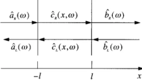
function parts that correspond to free fields incident on the slab surfaces from the regions of free space to its left and right. The notation for the operators associated with the rightwards and leftwards parts of the fields in the three spa-tial regions is illustrated in Fig. 1. The operators for the incoming fields on the left and right of the slab have the free-space commutators @aˆR~v!,aˆR †~v
8
!#5@bˆ L~v!,bˆL †~v8
!#5d~v2v8
!, ~3.1!and the operators for the two kinds of incoming wave com-mute,
@aˆR~v!,bˆL
†~v
8
!#50. ~3.2!A. Exterior regions
Consider first the complete fields exterior to the slab. The field on the left can be written in the form
Aˆ1~x,t!5
E
0 ` dvS
\ 4p«0cvSD
1/2 @aˆR~v!eivx/c1aˆL~v!e2ivx/c#e2ivt, x,2l, ~3.3!
where the operator for the leftward-propagating outgoing field is given by
aˆL~v!5RS~v!aˆR~v!1TS~v!bˆL~v!1FˆL~v!, ~3.4!
similar to I~5.11!. The outward-propagating noise operator is defined as FˆL~v!5i
S
2vh~v!uk~v!u cD
1/2 3E
2l l dx8
H
V~v!expS
ivn~v!x8
cD
1W~v!expS
2ivn~v!x8
cDJ
wˆ~x8
,v!. ~3.5!The amplitude reflection and transmission coefficients for the slab are given by
RS~v!52n~v! 221 D~v! exp
S
2 2ivl cD
3H
12 expS
4ivn~v!l cDJ
~3.6! and TS~v!5 4n~v! D~v! expS
2iv@n~v!21#l cD
. ~3.7!The coefficients in the integrand of the noise operator are
V~v!52@n~v!11# D~v! exp
S
iv@n~v!21#l
c
D
~3.8!and
FIG. 1. Representation of the dielectric slab, showing the nota-tion for the destrucnota-tion operators used in the defininota-tions of the vec-tor potential operavec-tor.
W~v!52@n~v!21# D~v! exp
S
iv@3n~v!21#l cD
, ~3.9! where D~v!5@n~v!11#22@n~v!21#2exp@4ivn~v!l/c#. ~3.10!The field on the right of the slab is given by
Aˆ1~x,t!5
E
0 ` dvS
\ 4p«0cvSD
1/2 @bˆR~v!eivx/c1bˆL~v!e2ivx/c#e2ivt, x.l, ~3.11!
where the operator for the rightwards-propagating outgoing field is given by
bˆR~v!5TS~v!aˆR~v!1RS~v!bˆL~v!1FˆR~v!, ~3.12!
similar to I~5.15!, and the form of the noise operator on the right is obtained from that on the left, given by Eq. ~3.5!, according to the prescription
FˆR~v!5FˆL~v! with x
8
→2x8
in the exponents.~3.13!
These outward propagating noise operators differ from those given in I by the occurrence of the modulus of the extinction coefficient in the square-root prefactors and by the generali-zation of the normalized noise current operator to the form defined in Eq.~2.21!.
It is straightforward, but algebraically lengthy, to show with the use of the commutator~2.22! and the forms of the coefficients ~3.6!–~3.9! that the noise operators in ~3.4! and
~3.12! have the commutators @FˆL~v!,FˆL
†
~v
8
!#5@FˆR~v!,FˆR†
~v
8
!#5@12uR~v!u22uT~v!u2#d~v2v
8
!~3.14! and @FˆL~v!,FˆR †~v
8
!#52@R S~v!TS*~v!1TS~v!RS*~v!# 3d~v2v8
!. ~3.15!These noise-operator commutators and the forms of the out-going field operators defined in Eqs. ~3.4! and ~3.12! have been applied in@18# to derive the field commutation relations in an optical cavity. It follows from the above expressions that the outgoing field operators have the simple free-space commutators @aˆL~v!,aˆL †~v
8
!#5@bˆ R~v!,bˆR †~v8
!#5d~v2v8
! ~3.16! and @aˆL~v!,bˆR † ~v8
!#50. ~3.17!Expressions for the electric- and magnetic-field operators on the left and right of the slab are readily obtained from Eqs.
~3.3! and ~3.11!, respectively, with the use of Eq. ~2.8!.
B. Interior region
The vector potential operator inside the dielectric slab has the form Aˆ1~x,t!5
E
0 ` dvS
\h~v! 4p«0cvn~v!2SD
1/2 @cˆR~x,v! 1cˆL~x,v!#e2ivt, 2l,x,l, ~3.18!where the operators associated with the rightward- and leftward-propagating fields are again linear combinations of the incoming field operators and noise contributions, with the forms cˆR~x,v!5
S
n~v! h~v!1/2@V~v!aˆR~v!1W~v!bˆL~v!# 1iS
2vuk~v!u cD
1/2 3H
E
2l l dx8
F
n~v! 221 D~v! expS
ivn~v!~2l1x8
! cD
1@n~v!21# 2 D~v! expS
ivn~v!~4l2x8
! cDG
wˆ~x8
,v! 1E
2l x dx8
expS
2ivn~v!x8
cD
wˆ~x8
,v!J
D
3expS
ivn~v!x cD
~3.19! and cˆL~x,v!5S
n~v! h~v!1/2@W~v!aˆR~v!1V~v!bˆL~v!# 1iS
2vukc~v!uD
1/2 3H
E
2l l dx8
F
n~v! 221 D~v! expS
ivn~v!~2l2x8
! cD
1@n~v!21# 2 D~v! expS
ivn~v!~4l1x8
! cDG
wˆ~x8
,v! 1E
x l dx8
expS
ivn~v!x8
cD
wˆ~x8
,v!J
D
3expS
2 ivnc~v!xD
, ~3.20!similar to I~5.17! and ~5.18!. The commutation relations for these operators are the same as given in the Appendix of I,
and there is no need to reproduce them here. Their equations of propagation are easily derived from Eqs.~3.19! and ~3.20! as ]cˆR,L~x,v! ]x 56i vn~v! c cˆR,L~x,v! 6 i
S
2vuk~v!u cD
1/2 wˆ~x,v!, ~3.21!where1 and 2 refer to right and left propagation, respec-tively. The electric- and magnetic-field operators inside the slab are straightforwardly derived from Eq.~2.8! with the use of Eqs. ~3.18! and ~3.21!. It has been shown in @6# that the same expressions for the vector potential operator as derived in the present section can be obtained by taking the propa-gation equation~3.21! as the starting point and applying the usual boundary conditions to the field operators at the sur-faces of the slab.
All of the field operators in the three spatial regions are expressed in terms of the two incoming fields associated with
aˆR(v) and bˆL(v), together with the noise field associated
withwˆ (x,v). The states of the entire system are thus defined by the states of the two incoming optical fields and by the expectation values of the noise operator. For specified inputs, the formalism allows the time development of the optical fields from their initial input states to be calculated.
C. Canonical commutation relation
The correctness of the quantized field operators can be tested by evaluation of the canonical commuator, which should have the value given in Eq. ~2.16!. The test can be carried out by use of the explicit forms of the field operators, as in@6#, or more concisely by use of the expression ~2.15!, which is determined by the same Green functions as the field operators themselves. The calculations are largely the same as presented for the attenuating dielectric in I, and it is not necessary to repeat most of the detail. However, the possi-bility that k(v) may be negative for some ranges of the frequency v requires additional consideration of the struc-tures of the poles in the various reflection and transmission coefficients. Thus, while «(v) continues to have all of its poles in the lower half of the complexvplane, as outlined in Sec. II, this condition is no longer automatically the case for some of the coefficients that are derived from«(v).
The reflection coefficient at each surface for light incident from inside the dielectric slab is
r~v!5n~v!21
n~v!11 [ur~v!uexp@ifr~v!#, ~3.22!
where the amplitude has the propertyur(v)u<1 for all val-ues of the frequency, whether v corresponds to dielectric loss or gain. The complex round-trip loss or gain for light that travels from a point in the slab and back to the same point after two surface reflections is
g~v!5r2~v!exp@4ivn~v!l/c#[ug~v!uexp@ifg~v!#,
~3.23!
where
ug~v!u5ur~v!u2exp@24vk~v!l/c#,
fg~v!52fr~v!1@4vh~v!l/c#. ~3.24!
The denominator~3.10! that occurs in the coefficients de-fined in Eqs.~3.6!–~3.9! can be written in the form
D~v!5@n~v!11#2@12g~v!#. ~3.25!
The numerators of these coefficients and the denominator
~3.25! are analytic functions of v in the upper half of the complexvplane and the coefficients are themselves analytic functions if 12g(v) has no zeros there. The zeros of 12g(v) occur for frequenciesv that simultaneously satisfy
ug~v!u51 ~3.26!
and
cos@fg~v!#51. ~3.27!
The function g(v) is also analytic in the upper half plane and ug(v)u accordingly takes its maximum value on the boundary of the half plane@19#. Now ug(v)u clearly tends to zero on the infinite semicircle, so that its maximum value must occur on the real axis. A sufficient condition for ana-lytic coefficients is therefore
ug~v!u,1 for real v, ~3.28! and this is always satisfied for frequencies associated with loss, wherek(v) is positive. However, for frequencies asso-ciated with gain, where k(v) is negative, the condition
~3.28! is satisfied only for
ur~v!u,exp@22vuk~v!ul/c#. ~3.29!
In this case the coefficients are indeed analytic functions of
v in the upper half plane, and the proofs of the canonical commutation relation~2.16! for the different regions of space proceed in exactly the same ways as presented in I for the purely attenuating dielectric. These proofs justify the nor-malization of the noise commutator assumed in Eq. ~2.17!.
The conditions ~3.26! and ~3.27! determine the threshold for laser action, when the state of the optical field in the amplifying slab transforms into one of self-sustaining oscil-lation. The two conditions must be satisfied simultaneously for the lasing frequencies v. Condition ~3.26! specifies a gain in the dielectric that is sufficient to offset the loss of optical energy through the slab surfaces while condition
~3.27! specifies phase matching of the light after a round trip
in the slab. We do not consider the properties of the lasing slab here.
IV. SLAB AMPLIFICATION OR ATTENUATION AND NOISE
The slab acts as an amplifier or attenuator for radiation incident from the free space on its left or right. The system must also produce noise in amounts whose minimum values are controlled by very general requirements derived from the relations between input and output operators @20#. We show in the present section how the gain and the noise derived from the slab properties obtained above conform to these
requirements. We also evaluate the electric-field fluctuations in the three spatial regions.
A. Gain and noise
The slab geometry shown in Fig. 1 is symmetrical, and we need consider only its effects on light that is incident from the free space on its left, with the incident field from the right taken to be in its vacuum state. Thus, with the use of Eqs.
~3.4! and ~3.12!, the output photon-number fluxes on the left
and right of the slab are determined by the expectation val-ues
^
aˆL†~v!aˆL~v8
!&
5GR~v!^
aˆR†~v!aˆ R~v
8
!&
1^
FˆL †~v!Fˆ L~v8
!&
~4.1! and^
bˆR†~v!bˆR~v8
!&
5GT~v!^
aˆR †~ v!aˆR~v8
!&
1^
FˆR†~v!FˆR~v8
!&
. ~4.2! The intensity gains in reflection and transmission are defined byGR~v!5uRS~v!u2 ~4.3!
and
GT~v!5uTS~v!u2, ~4.4!
respectively, where the reflection and transmission coeffi-cients are given by Eqs. ~3.6! and ~3.7!. We use the term ‘‘gain’’ for simplicity to cover both amplifying and attenu-ating frequencies, when the G(v) are greater or smaller than unity, respectively. These gains have the properties
GR~v!1GT~v!.1 for k~v!,0
51 for k~v!50
,1 for k~v!.0.
~4.5!
Both the reflection and transmission coefficients have the denominator D(v), which can be written in the form~3.25!, and they therefore have the proportionality
G~v!} 1
u12g~v!u25
1
11ug~v!u222ug~v!ucos@fg~v!#
,
~4.6!
where Eq.~3.23! has been used. The gains have their maxi-mum values for cos@fg(v)#51 when
Gmax~v!} 1
@12ug~v!u#2 ~4.7!
and infinite gain occurs forug(v)u51, corresponding to the threshold for laser action discussed in Sec. III C. The gain remains finite for ug(v)u,1 and Eq. ~4.6! takes half its maximum value~4.7! when
cos@fg~v!#512
@12ug~v!u#2
2ug~v!u . ~4.8!
Thus, as the round-trip gainug(v)u approaches the threshold value of unity,fg(v) at half maximum gain differs from its
value at maximum gain ~an integer multiple of 2p) by ap-proximately 6@12ug(v)u#. The full width of the gain pro-file at half maximum height close to threshold is now ob-tained from the second line of Eq.~3.24! as
Dv5c@12ug~v2h~v!l!u#. ~4.9!
The divergence in peak gain~4.7! and the narrowing of the gain profile shown by Eq.~4.9! on the approach to threshold are well-known features of standard laser theory@21#.
The output noise operator expectation values that occur in Eqs.~4.1! and ~4.2! are readily obtained from essentially the same calculation that produces the commutation relations
~3.14!, with the help of the corresponding expectation values
for the noise current operator given in Eqs.~2.28! and ~2.29!. The results can be written in the forms
^
FˆL†~v!FˆL~v8
!&
5^
FˆR † ~v!FˆR~v8
!&
5F
N~v,uTu!11 2N~v,T!G
3$GR~v!1GT~v!21%d~v2v8
! ~4.10! and^
FˆL~v!FˆL †~v8
!&
5^
Fˆ R~v!FˆR †~v8
!&
5F
N~v,uTu! 2N~v,T!21G
3$GR~v!1GT~v!21%d~v2v8
!, ~4.11!where here, and subsequently, the upper and lower entries in the column matrix refer to frequencies for which the dielec-tric is amplifying and attenuating, respectively. These expec-tation values are always positive or zero in accordance with the inequalities in Eq. ~4.5!. The subtraction of Eq. ~4.10! from Eq. ~4.11! produces expressions consistent with the commutator ~3.14! for both cases of amplification and at-tenuation.
The dielectric slab considered here is an example of a phase-insensitive linear amplifier, whose output noise opera-tors must satisfy the requirements of general amplification theory @20#. The theory needs some extensions to cover the kind of amplifier considered here, in which there are two inputs and two outputs @22#, and the generalizations of Eqs.
~4.19b! and ~4.21! of @20# give
^
Fˆ~v!Fˆ†~v8
!1Fˆ†~v8
!Fˆ~v!&
>uGR~v!1GT~v!21ud~v2v
8
!, ~4.12!which must be satisfied by the noise operators on both the left and right of the slab. We note from Eq. ~4.5! that the modulus signs in Eq.~4.12! have no effect fork(v),0, but they reverse the signs of the terms within fork(v).0. Use
of the explicit noise operator expectation values for the am-plifying or attenuating slab obtained from Eqs. ~4.10! and
~4.11! gives
^
FˆL~v!FˆL †~v8
!1Fˆ L †~v8
!Fˆ L~v!&
5^
FˆR~v!FˆR † ~v8
!1FR † ~v8
!FˆR~v!&
5F
2N~v,uTu!11 22N~v,T!21G
$GR~v!1GT~v!21%d~v2v8
!, ~4.13!and the positive or zero values of the population factors
N(v,T) and N(v,uTu) ensure that the inequality in Eq.
~4.12! is indeed satisfied.
B. Electric-field fluctuations
The noise properties of the system are also manifested by the electric-field fluctuation spectrum in the absence of any input signal, which determines the contributions of the waves that propagate perpendicular to the slab to such properties as atomic spontaneous emission rates and Casimir forces. The power spectrum S(x,v) of the electric field fluctuations at position x is defined by
^
Eˆ~x,v!Eˆ~x,v8
!&
5S~x,v!d~v2v8
!, ~4.14!where the angular brackets denote an expectation value with respect to the vacuum states of the incoming fields described by the operators aˆR(v) and bˆL(v) and the positive- or
negative-temperature thermal states of the noise field in the amplifying or attenuating slab.
We have previously used the fluctuation-dissipation theo-rem to obtain expressions for the power spectra associated with various configurations of attenuating dielectrics at zero temperature @1,2,5#. Fluctuation-dissipation theorems have also been derived for amplifying media @23–25#. However, this approach cannot be used when the system as a whole is not in thermal equilibrium @26#, as in the present example where an attenuating or amplifying dielectric at elevated positive or negative temperature is surrounded by free space at zero temperature.
The required power spectra can, however, be derived by direct substitution of the electric-field operators in the defi-nition~4.14!. Consider first the free space on the right of the slab where the electric field operator obtained from Eqs.
~2.8!, ~3.11!, and ~3.12! is Eˆ1~x,v!5i
S
\v 2«0cSD
1/2 $@TS~v!aˆR~v!1RS~v!bˆL~v! 1FˆR~v!#eivx/c1bˆL~v!e2ivx/c%. ~4.15!Substitution in Eq.~4.14! then leads to an exterior spectrum
Sex~x,v!5 \v «0cS
H
11Re@RS~v!e2ivx/c#1F
N~v,uTu!11 2N~v,T!G
3@uRS~v!u21uTS~v!u221#
J
~4.16!for x.l, where Eqs. ~3.1!, ~4.3!, ~4.4!, and ~4.13! have been used. For a blackbody limit in which both the reflection and transmission coefficients vanish, the exterior spectrum of an absorbing slab reduces to
Sex~x,v!5
\v «0cS@N~v
,T!11#. ~4.17!
Here the thermal factor can be separated into a contribution from N(v,T) blackbody photons plus a 12 vacuum part
propagating away from the slab and another 12 vacuum
con-tribution propagating towards the slab. The former contribu-tion agrees with the one-dimensional form of the blackbody spectrum@4,17#.
The electric-field operator in the interior of the slab is similarly obtained with the use of Eqs.~3.18!–~3.20!, and the resulting power spectrum can be written as
Sin~x,v!5Svac~x,v!1
F
N~v,uTu!11 2N~v,T!G
$SRL~x,v! 22Svac~x,v!% ~4.18! for 2l,x,l, where Svac~x,v!5 \v «0cS 1 un~v!u2ReS
n~v! 1n*~v!@n~v!21#expS
iv@n~v!11#l cD
3H
W~v!1V~v! 2F
expS
2ivn~v!x cD
1expS
22ivn~v!x cDGJD
~4.19!is the power spectrum for an attenuating slab at zero tem-perature and SRL~x,v!5 \v «0cS@uV~v !eivn~v!x/c1W~v!e2ivn~v!x/cu2 1uW~v!eivn~v!x/c1V~v!e2ivn~v!x/cu2# ~4.20!
contains the contributions to the spectrum from the incoming modes aˆR(v) and bˆL(v), respectively. For an attenuating
slab with incoming modes from free-space regions main-tained at the same temperature T as the medium, the power spectrum can be obtained independently from the fluctuation-dissipation theorem in the form
Sin~x,v!5@2N~v,T!11#Svac~x,v!, ~4.21! and the same result follows from Eq. ~4.18! when
SRL(x,v) is neglected. Thus SRL(x,v) plays the role of a
correction to allow for the fact that the free spaces on both sides of the slab are here assumed at zero temperature, and there are accordingly N(v,T) fewer photons incident on the slab from each side.
The exterior and interior power spectra~4.16! and ~4.18! have similar structures with sums of temperature-independent and temperature-dependent terms. It can be shown by lengthy algebra that the former terms have equal values and equal spatial derivatives at x5l while the latter terms have equal values and zero spatial derivatives there. The spectra show maxima at frequencies for which Eq.
~3.27! is satisfied, when the round-trip phase shift ~3.24!
in-side the dielectric slab is an integer multiple of 2p, leading to a buildup of the field fluctuations.
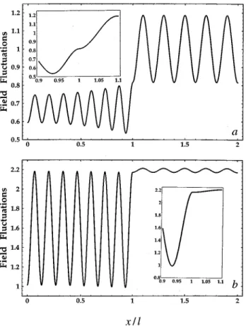
Figure 2 shows two examples of the spatial dependences of the power spectrum S(x,v) of electric-field fluctuations for a frequency at which amplification occurs. The fluctua-tions are symmetrical around x50, and only positive values of x are included in the figure. Figure 2~a! shows the spatial dependence for zero effective temperature, where the two-level population is perfectly inverted, while Fig. 2~b! shows the fluctuations for an elevated negative temperature, where the amplification is reduced by the effects of saturation. The population factor that occurs in the dielectric function ~2.6! for the two-level model can be written
Nl1Nu
Nl2Nu
5
F
22N~v,uTu!212N~v,T!11
G
, ~4.22!where the definitions ~2.25! and ~2.27! have been used for the amplifier and attenuator, respectively. The change in this population factor with an increase in the magnitude of the temperature affects both the refractive index and extinction coefficient. However, for a refractive index that greatly ex-ceeds the extinction coefficient, a change in the population factor mainly influences the extinction coefficient, whose value at elevated negative temperature is assumed to be re-lated to its valuek0(v) at zero negative temperature by@17#
k~v!5 k0~v!
2N~v,uTu!11, ~4.23!
and this relation has been used in the construction of Fig. 2~b!. Despite appearances to the contrary, the spectra have continuous values and slopes at x5l as is shown in the large-scale inserts of the boundary region. For the parameter val-ues given in the figure caption, the value of the extinction coefficient at the lasing threshold obtained from Eq.~3.29! is
k(v)520.051, so that Fig. 2~a! represents conditions quite close to threshold. Both the internal and external fluctuations are decreased for the conditions of elevated negative tem-perature and reduced gain shown in Fig. 2~b!. FIG. 2. Spatial variation of the spectrum S(x,v) of electric-field
fluctuations in the vicinity of an amplifying dielectric slab, normal-ized to the vacuum free-space value. The slab thickness is 2l510pc/v and h(v)51.5. The other parameters are (a) uTu50 and k(v)520.04, giving GR(v)519.8 and
GT(v)543.5, and (b) uTu5180\c/kBl andk(v)520.0017,
giv-ing GR(v)50.00055 and GT(v)51.12. The insets show the
boundary regions in more detail.
FIG. 3. Spatial variation of the spectrum S(x,v) of electric-field fluctuations in the vicinity of an attenuating dielectric slab, normal-ized to the vacuum free-space value. The slab thickness is 2l510pc/v andh(v)51.5. The other parameters are (a) T50 and k(v)50.04, giving GR(v)50.034 and GT(v)50.075, and
(b) T5180\c/kBl and k(v)50.0017, giving GR(v)50.000 44
and GT(v)50.89. The insets show the boundary regions in more
Similar remarks apply to Fig. 3, where the two parts show the spatial dependences of the electric-field fluctuations as-sociated with an attenuating slab at zero and an elevated temperature, the extinction coefficients at the two tempera-tures being related by~4.23! with the modulus sign removed. Fig. 3~a! is similar to Fig. 3 in I and corresponds to condi-tions of equilibrium at zero temperature where the fluctuation-dissipation theorem is valid. It shows the effects of the slab in causing oscillations of the mean-square electric field around the usual free-space value in the exterior regions and around a value reduced by the factor h(v)/un(v)u2 in the interior, as discussed in I. Figure 3~b! shows the en-hanced internal fluctuations and reduced external fluctuations at an elevated temperature. The insets again show the conti-nuities of the slopes of the spectra at x5l.
It is evident from Figs. 2~b! and 3~b! that similar electric-field fluctuations occur for an amplifier at elevated negative temperature and an attenuator at elevated positive tempera-ture. It can be shown that for frequencies such that 4vh(v)l/c is an integer multiple of 2p the spectra
~4.16! and ~4.18! tend to the common high-temperature
forms Sex~x,v!5 \v «0cS
H
11vuk0~v!ul c h~v!211 h~v!J
~4.24! and Sin~x,v!5 \v «0cS 1 2h~v!2H
11 vuk0~v!ul c h~v!211 h~v!J
3$h~v!2111@h~v!221# 3cos@2vh~v!x/c#cos@2vh~v!l/c#%. ~4.25!These expressions are valid as T→2` for the amplifier and as T→` for the attenuator, where the physical states of the medium are identical, with equal populations in the upper and lower levels of the dipole-active transitions.
V. CONCLUSIONS
We have generalized earlier work on the quantization of the electromagnetic field in attenuating dielectrics to cover a dielectric slab that shows amplification over some ranges of frequency. The extinction coefficientk(v) is thus allowed to take negative as well as positive values, with a functional form that is limited only by the requirements of causality. We have derived the forms of the electromagnetic field op-erators inside the slab and in the free-space regions on either side for waves propagated normal to the slab surfaces. The slab approaches a threshold for laser action whenk(v) takes increasing negative values up to a point where the gain in-side the slab overcomes the losses to the outin-side by trans-mission through the surfaces. We have identified the pres-ence of laser threshold effects in the quantized field operators, but have confined our treatment to the regime of linear amplification below threshold. The appropriate canoni-cal commutation relations for the conjugate vector potential
and electric-field operators in the three spatial regions are satisfied in this regime.
The quantum formalism has been used to derive the am-plification and noise properties of the dielectric slab in terms of the intensity gains for a signal incident from free space observed in reflection from or transmission through the slab. The gain profiles show the usual narrowing effects on the approach to the lasing threshold. The amounts of noise added to the amplified, or attenuated, signals have been shown to accord with the minimum values required by a generalization of standard amplifier theory for a slab with two inputs and two outputs. The quantum-mechanical nature of the formal-ism ensures that it applies to the amplification of nonclassical light, as well as light whose gain characteristics could be obtained from a classical derivation. For any kind of incident light, the added noise is a basic quantum-mechanical phe-nomenon that can only be rigorously computed by the quan-tum theory.
Previous work on the quantization of the electromagnetic field in dielectrics has employed models in which the centers of amplification or attenuation are represented by beam splitters, whose input-output relations allow for illumination of the spare input ports with light from harmonic oscillators in inverted or normal states, respectively @15#. This method has been applied to sections of amplifying and attenuating media embedded in inert media of infinite extent @16#. It has also been used in quite sophisticated modeling of spatial and temporal effects in semiconductor lasers in Fabry-Pe´rot cavities @27#. The results obtained by such models are in qualitative agreement with the more rigorous theory developed here. However, it is difficult to combine the beam-splitter representation with a satisfactory fulfilment of the standard electromagnetic boundary conditions at the surfaces of a finite specimen. By contrast, the formalism presented here can be applied to the study of linear amplifi-cation in a finite inverted-population medium, with rigorous inclusion of the spatial effects caused by its sur-faces.
The theory developed here is adequate for a wide range of experiments where the light beams are propagated normally through the surfaces of the optical components. Extensions to include all directions of propagation are needed for the treatment of processes such as the spontaneous emission by atoms close to or inside dielectrics and the Casimir pres-sures exerted on dielectric surfaces, where there is no restric-tion on the spatial direcrestric-tions involved. Such extensions greatly complicate the derivations, and they are reserved for future work.
ACKNOWLEDGMENTS
We thank Dr. C. R. Gilson, Dr. M. Harris, and Dr. C. H. Henry for helpful discussions. This work was supported by the European Community Human Capital and Mobility Pro-gramme through its network on ‘‘Nonclassical Light’’ with Contract No. CHRX-CT93-0114. R.M. thanks the University of Kerman Research Council and J.J. thanks the United Kingdom Engineering and Physical Sciences Research Council for financial support.
@1# S. M. Barnett, R. Matloob, and R. Loudon, J. Mod. Opt. 42, 1165~1995!.
@2# R. Matloob, R. Loudon, S. M. Barnett, and J. Jeffers, Phys. Rev. A 52, 4823~1995!.
@3# T. Gruner and D.-G. Welsch, Phys. Rev. A 51, 3246 ~1995!;
53, 1818~1996!.
@4# M. Artoni and R. Loudon, Phys. Rev. A 55, 1347 ~1997!. @5# R. Matloob and R. Loudon, Phys. Rev. A 53, 4567 ~1996!. @6# J. Jeffers, S. M. Barnett, R. Loudon, R. Matloob, and M.
Ar-toni, Opt. Commun.. 131, 66~1996!.
@7# L. D. Landau, E. M. Lifshitz, and L. P. Pitaevskii, Electrody-namics of Continuous Media, 2nd ed. ~Pergamon, Oxford, 1984!, Sec. 82.
@8# M. Altarelli, D. L. Dexter, H. M. Nussenzveig, and D. Y. Smith, Phys. Rev. B 6, 4502~1972!.
@9# H. M. Nussenzveig, Causality and Dispersion Relations ~Aca-demic, New York, 1972!.
@10# L. W. Davies, Proc. IEEE 51, 76 ~1963!.
@11# T. A. Weber and D. B. Trizna, Phys. Rev. 144, 277 ~1966!. @12# R. Y. Chiao, Phys. Rev. A 48, R34 ~1993!.
@13# F. Bassani and S. Scandolo, Phys. Rev. B 44, 8446 ~1991!. @14# S. Scandolo and F. Bassani, Phys. Rev. B 45, 13 257 ~1992!.
@15# R. J. Glauber, in Frontiers in Quantum Optics, edited by E. R. Pike and S. Sarkar~Hilger, Bristol, 1986!, p. 534.
@16# J. R. Jeffers, N. Imoto, and R. Loudon, Phys. Rev. 47, 3346 ~1993!.
@17# C. H. Henry and R. F. Kazarinov, Rev. Mod. Phys. 68, 801 ~1996!.
@18# S. M. Barnett, C. R. Gilson, B. Huttner, and N. Imoto, Phys. Rev. Lett. 77, 1739~1996!.
@19# Z. Nehari, Conformal Mapping ~McGraw-Hill, New York, 1952!.
@20# C. M. Caves, Phys. Rev. D 26, 1817 ~1982!.
@21# A. E. Siegman, Lasers ~University Science Books, Mill Val-ley, CA, 1986!, pp. 443–451.
@22# S. M. Barnett, A. Gatti, J. Jeffers, and R. Loudon ~unpub-lished!.
@23# P. N. Butcher and N. R. Ogg, Proc. Phys. Soc. 86, 699 ~1965!. @24# M.-A. Dupertuis and S. Stenholm, J. Opt. Soc. Am. B 4, 1094
~1987!.
@25# S. Tarzi, J. Phys. A 21, 3105 ~1988!.
@26# L. D. Landau and E. M. Lifshitz, Statistical Physics, 3rd ed. ~Pergamon, Oxford, 1980!, Pt. 1, Sec. 123.