VOLUME86, NUMBER12 P H Y S I C A L R E V I E W L E T T E R S 19 MARCH2001
Fresnel Light Drag in a Coherently Driven Moving Medium
M. Artoni,1 I. Carusotto,2G. C. La Rocca,3,2and F. Bassani2 1I.N.F.M., L.E.N.S., Largo E. Fermi 2, 50125 Florence, Italy
2I.N.F.M., Scuola Normale Superiore, Piazza dei Cavalieri 7, 56126 Pisa, Italy 3Dipartimento di Fisica, “E. R. Caianiello,” Università di Salerno, 84081 Baronissi (Sa), Italy
(Received 18 September 2000)
We theoretically study how the phase of a light plane wave propagating in a resonant medium under electromagnetically induced transparency (EIT) is affected by the uniform motion of the medium. For cuprous oxide共Cu2O兲, where EIT can be implemented through a typical pump-probe configuration, the
resonant probe beam experiences a phase shift (Fresnel-Fizeau effect) that may vary over a wide range of values, positive or negative, and even vanishing, due to the combined effects of the strong frequency dis-persion and anisotropy both induced by the pump. The use of such a coherently driven dragging medium may improve by at least 1 order of magnitude the sensitivity at low velocity in optical drag experiments. DOI: 10.1103/PhysRevLett.86.2549 PACS numbers: 42.50.Gy, 03.30. +p The phase velocity of light depends on whether light
propagates in a moving or in a stationary medium. This effect, which gives rise to the familiar Fresnel light drag [1,2], has been observed for the first time in Fizeau’s flow-ing water experiment [3] and had a profound influence on the change of our perception [4] of the nature of space and time at the turn of the century.
We here anticipate that light drags can be made to vary over a rather wide range of values when a slab of coherently driven cuprous oxide共Cu2O兲 is used as a dragging medium. This originates from the steep electromagnetically induced transparency (EIT) dispersion [5,6] occurring at the 2P-exciton resonance in a typical pump and probe L-configuration [7]. Furthermore, in a sample rendered anisotropic by a suitable choice of the pump and probe polarizations, one can also make the light drag vanish over a broad range of probe frequencies depending on the pump parameters. This means that in a typical interferometric experiment no fringe shift would be observed for light propagating through a moving medium with respect to light propagating through the same medium at rest. Such a somewhat surprising conclusion holds for all velocities of experimental interest and has been found so far to hold only in the very different context of matter waves where a null drag has been observed for thermal neutrons traversing a nonresonant moving medium contained inside stationary boundaries [8].
Since Fizeau’s experiment various other observations of light drags have followed in which different dragging me-dia and diverse interferometric measurement techniques have been employed, but there still remains a formidable challenge to perform high-precision measurements of light drags; these, in fact, have not yet reached the level of accu-racy of other tests of special relativity [9]. In order to per-form a high-precision measurement of the Fresnel-Fizeau effect one needs high sensitivity to velocity induced phase shifts, which in turn sets a lower bound for the usable sample speeds. At the same time, in order to preserve high contrast of the interference fringe pattern, mechanical
vi-brations from the sample movement have to be minimized. Owing to the high dispersion at the 2P-exciton resonance, where absorption is also largely quenched by quantum interference, this goal can be achieved by using a slab of coherently driven cuprous oxide 共Cu2O兲 as a dragging medium: interferometric sensitivity at low drag velocities can be increased by at least 1 order of magnitude.
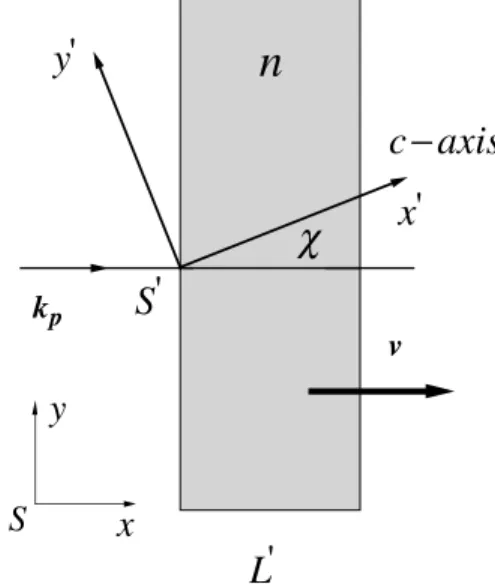
The dragging medium, in the form of a parallel-sided slab, induces an optical phase shift which we here cal-culate from first principles including the effects of fre-quency and angular dispersion. We take a slab moving in one arm of the interferometer with constant velocity y with respect to an observer in the laboratory frame S. The rele-vant geometry is illustrated in Fig. 1. Phase shifts depend crucially on boundary conditions and our configuration, unlike in the historic work of Fizeau [3] where the phase
x'
c
−axis
y'
S'
χ
L'
v kpS
x
y
n
FIG. 1. Probe-beam path across a Cu2O slab moving with
ve-locity y in the laboratory frame S. The probe wave vector kp, the slab velocity, and its surface normal are all in the same direction ˆx. The pump wave vector is along ˆz苷 ˆz0and its polarization is par-allel to the optical c axis ˆx0which makes a fixed angle x with ˆx.
VOLUME86, NUMBER12 P H Y S I C A L R E V I E W L E T T E R S 19 MARCH2001 shifts were produced by water flowing inside stationary
tubes, realizes a situation in which the medium boundaries are in motion [10]. Note that we do not account here for small tilt angles between the surface normal and the inter-ferometer ˆx axis commonly employed to minimize back-reflections and to avoid multiple internal back-reflections [9]. Such a geometry is in fact sufficient to illustrate [11] the effects of frequency and angular dispersion associated with EIT on the light drag and we then proceed to derive the phase shift for a beam single-pass even if this occurs at nor-mal incidence. The phase shift is in general associated with a space-time contour, i.e., Df苷H共v dt 2 k ? dr兲, which accounts for the temporal and spatial variations exhibited by a plane wave of wave vector k and angular frequency v propagating in the medium. In our approach, we set all times to be identical in the laboratory frame S and we evaluate Hkp ? dr along the probe optical path in the interferometric arrangement required for a typical high-precision measurement of the drag [9,12].
Because the phase shift is relativistically invariant, we find it convenient to derive its expression in the slab rest frame S0. The space-time coordinates as well as the fre-quency (vp) and wave vector共kp兲 of the probe light wave in S and S0are connected through a Lorentz transformation [13] which comprises a boost along x and a rotation about the z axis. To the lowest order in b 苷 y兾c, the single pass phase shift is Df苷 Df0 苷 vp0Dt0 2 kp0 ? Dr0 ⯝ 2bv 0 RL0 c 2 k 0 RL 0 苷 2v 0 RL0 c 兵Re关n共v 0 R, x兲兴 1 b其 , (1)
where primed and unprimed variables refer, respectively, to the slab rest frame S0 and the laboratory frame S and where we have replaced vp0 by vR0 and kp0 by k
0
R for the frequency and wave vector of the refracted probe beam propagating inside the slab. Here n共v0R, x兲 denotes the complex index of refraction of the uniaxial medium in its rest frame S0, while L0is the actual slab thickness.
Since the slab surfaces are stationary in S0, there is no frequency change at the sample boundaries and the fre-quency of the refracted wave is equal to that of the incident one, i.e., vR0 苷 v
0
I, while the incident probe frequency in
Sand S0 are related, to the lowest order in b, by
vI0 ⯝ vI 2 bvI. (2)
Such a Doppler shift is quite small and the refractive index can then be expanded as
n共v0R, x兲 ⯝ n共vI, x兲 2 bvI ≠n共v 0 I, x兲 ≠vI0
, (3)
where the derivative is to be evaluated at v0I 苷 vI. Sub-stituting (2) and (3) back into (1) yields
Df 苷 2vIL 0 c Re关n共vI, x兲兴 2 b vIL0 c 3 ∑ 1 2 Re关n共vI, x兲兴 2 vI ≠ Re关n共vI, x兲兴 ≠vI ∏ ⬅ Dfo 2 b vIL 0 c ae. (4)
This gives the relative phase of the incident and emerging beams as viewed in the laboratory frame to first order in b. Here Dfo is the shift induced by a stationary sample, while the additional term on the right hand side of (4) arises from the sample motion and defines in turn the effective drag coefficient ae [9]. This is a measurable quantity as the nonreciprocal phase shift between the light beams propagating parallel and antiparallel to the velocity of the sample, that is proportional to ae, can easily be measured through standard high-precision interferometric techniques [9,12]. The usual definition [2] of the drag coefficient for the phase velocity of light can easily be related to the measurable quantity ae[9].
We specifically evaluate the effective drag coefficient aeexperienced by a weak probe beam crossing a slab of Cu2O under EIT [7] used as a dragging medium; this is realized by tuning the probe about the 2P yellow exciton line of resonant frequency v2P and by further driving the sample with a strong pump beam of Rabi frequency Vcand frequency vctuned to the 1S-2P exciton transition. The quadrupole allowed threefold degenerate 1S exciton state (G51) has a small linewidth 共 ¯hg1S ⯝ 0.1 meV兲 compared to that ( ¯hg2P ⯝ 1 meV兲 of the second class dipole allowed threefold degenerate 2P-exciton state共G42兲. For a pump Rabi frequency Vc 艐
p
g2Pg1S EIT takes place whereby a narrow transparency window associated with a rather steep dispersion appears about the 2P-exciton line [7]. The effective dielectric tensor describing the optical response of the medium to the weak probe in the presence of the pump can be derived from a L-type model Hamiltonian as developed in [7] and, in general, will be anisotropic. The specific form of the effective dielectric tensor depends on the detailed structure of the exciton levels involved and on the pump polarization. For the sake of simplicity, we here assume that the G24 states are well separated from all other 2P states and we take the pump polarization along the cubic axis ˆx0 (see Fig. 1). The resulting dielectric tensor is uniaxial with the optical c axis along ˆx0, i.e., ex0x0 苷 ek,
ey0y0 苷 ez0z0 苷 e⬜, and ej0fik0 苷 0, where e⬜共v0R兲 苷 eEIT共v0R兲 苷 e`1 Ag2P共D 2 ig1S兲 共dp2 ig2P兲 共D 2 ig1S兲 2 Vc2兾4 , (5) while ek共vR0兲 is obtained by setting Vc ! 0 in the above equation. Here A⯝ 0.02 is a numerical constant propor-tional to the 2P exciton oscillator strength [7], e` ⯝ 6.5 1
i 2 3 1023is the background dielectric constant, while D 2550
VOLUME86, NUMBER12 P H Y S I C A L R E V I E W L E T T E R S 19 MARCH2001 is the relative detuning共dp 2 dc兲 with dp 苷 v2P 2 v
0 R and dc苷 v2P 2 v1S 2 vc0. Under EIT the dispersion equation for a probe (linearly) polarized in the x0y0plane is that of an extraordinary ray [14] whose complex refractive index is given by n2共vR0, x兲 苷 ek共v 0 R兲 1 1 er共v0 R兲 cos2x ; er共vR0兲 ⬅ ek共vR0兲 e⬜共vR0兲 2 1 . (6)
Unlike in the absence of EIT for which er 苷 0, not all variables involving the reduced dielectric function er van-ish, some variables acquiring smaller values than others for probe frequencies within the transparency bandwidth [7]. With the pump exactly resonant (dc苷 0), Re关er兴 and the frequency derivatives of Im关ek兴 and Im关er兴 take on vanish-ingly small values for a nearly resonant probe up to probe detunings of several tenths of g2P and a more compact form of the drag is obtained after setting these variables to zero in (4). The resulting form of ae can be further sim-plified observing that in the same detuning range the re-maining variables are nearly constant, acquire fairly larger values but still less than unit共1023 4 1022兲, and increase according to jIm关er兴j , g2Pj≠vRe关er兴j # Im关ek兴 & g2Pj≠vRe关ek兴j. It is then possible to carry out a suc-cessive series expansion of ae with respect to Im关er兴, g2P≠vRe关er兴 and Im关ek兴 to obtain, to the lowest order,
ae ⯝ 1 2 q Re关ek兴 2 vI 2pRe关ek兴 3 µ≠ Re关e k兴 ≠vI 2 Re关ek兴 cos2x ≠ Re关er兴 ≠vI ∂ . (7) Higher order contributions containing terms proportional to the product of Im关er兴, Im关ek兴, g2P≠vRe关ek兴 and of Im关er兴, g2P≠vRe关er兴, Im关ek兴 have been neglected and the frequency dependencies of all dielectric functions are not explicitly indicated.
The magnitude of aemay be controlled directly by vary-ing the intensity of the pump beam共Vc兲 and the cleavage angle (x) so that the drag may acquire positive and nega-tive values or it may even drop to zero. The first two terms on the right hand side of (7) are in fact of the same order of magnitude and much smaller than the last two in the bracket which are the dominant contributions to the drag. For appropriate choices of Vc’s and x’s these two terms may also become comparable in magnitude so as to make the overall drag to vanish at probe frequencies which are determined by the specific selection of pump and cleavage parameters. For each probe detuning and set cleavage, there exists a pump intensity at which jaej is maximum and one for which ae vanishes. Note, in particular, that the second of those terms does not appear in the absence of the pump beam, i.e., when ek 苷 e⬜ and er 苷 0; the fre-quencies at which jaej is largest can no longer be tuned in this case but are fixed by the material parameters.
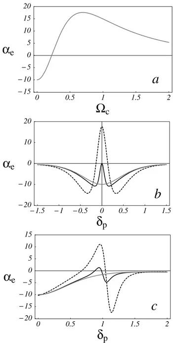
We report in Figs. 2 and 3 numerical results obtained from (7) for a resonant and a detuned pump. Because of the high dispersion at the 2P-exciton EIT resonance, where the absorption is quenched by quantum inter-ference, large drags are associated with an appreciable degree of transparency in the region jdp 2 dcj , 0.5g2P, where the observation of either large or vanishing drags should be favored. At exact resonance, aemax⯝ 18 occurs with over 20% transparency whereas ae vanishes for slightly detuned probes with a little smaller transparency. These figures exceed those in the absence of the pump where, e.g., jamax
e j⯝ 10 occurs with only a few percent
0 0.5 1 1.5 2
Ω
c
− 15 − 10 − 5 0 5 10 15 20α
e
a
− 1.5 − 1 − 0.5 0 0.5 1 1.5δ
p
− 20 − 10 0 10 20α
e
b
0 0.5 1 1.5 2δ
p
− 20 − 15 − 10 − 5 0 5 10 15α
e
c
FIG. 2. Coefficient ae vs Vc in units of g2P for a resonant
probe (a). Coefficient ae vs dp in units of g2P for a Rabi
fre-quency of Vc兾g2P 苷 0 (grey line), 0.22 (solid line), and 0.7
(dashed line) for a resonant (b) and detuned (c) pump with dc兾 g2P 苷 1. Here the cleavage angle is x 苷 5±and g2P 苷 1 meV. 2551
VOLUME86, NUMBER12 P H Y S I C A L R E V I E W L E T T E R S 19 MARCH2001 − 1.5 − 1 − 0.5 0 0.5 1 1.5
δ
p
0.05 0.1 0.15 0.2 0.25 0.3T
ransmission
a
0 0.5 1 1.5 2δ
p
0.05 0.1 0.15 0.2 0.25 0.3 0.35 0.4T
ransmission
b
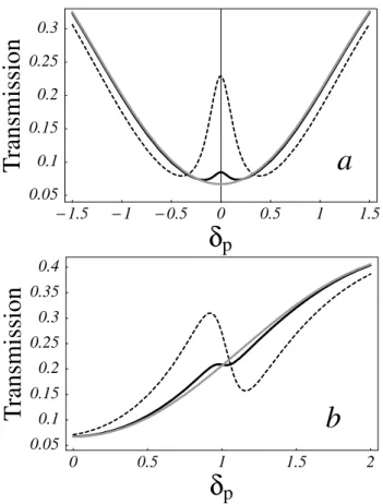
FIG. 3. Transmission coefficient for a resonant (a) and detuned (b) pump. The slab has a thickness L0 苷 25 mm, while the other parameters are the same as in Fig. 2.
transparency. The situation improves further with the pump detuning: where amaxe ⯝ 12 with a 30% trans-parency, while zeros of aeoccur with a 20% transparency. A large aeimproves the accuracy of drag measurements since interferometric techniques measure (Df 2 Dfo) that is proportional to the product b 3 ae [9,12]. The present values of ae exceed by at least 1 order of magnitude those for glass media [9]. At the 2P-exciton resonance ≠lpRe关ek, er兴 varies in the range 10 4 40 mm21 that is just about 1 to 2 orders of mag-nitude larger than typical dispersions for glass media [9]. Note that the dephasing g1S plays an important role. Reducing it to half its value would produce a further 35% increase in the magnitude of ae with a concomitant 50% increase in the transparency window whose width would then narrow down to nearly a third of g2P.
Our situation resembles much the one of neutron de Broglie waves in matter [15] where the dispersive con-tribution to the drag can compare with or exceed that deter-mined by the refractive index of the medium. Matter waves and light waves in moving media share another and peculiar feature, i.e., the fact that the drag may vanish. In our case, in particular, the drag can vanish over a wide range of opti-cal frequencies and such a remarkable behavior originates from the fact that around the 2P-exciton EIT resonance
the two terms in the bracket of (7) may cancel with one another. To the best of our knowledge, null drags have so far been observed only for thermal neutrons traversing a moving medium contained inside stationary boundaries and exhibiting no nuclear resonance [8]. While it follows as a general result [16] that no neutron Fizeau effect occurs for an off resonance neutron probe and boundaries at rest, it is here worthwhile to note that in our case a null effect is instead exhibited for a light probe either on or off resonance and moving boundaries. The null result depends in one case on the specific form of the dispersion relation for neutrons in material media while on the other it depends both on the EIT dispersion and on the associated anisotropy of light waves in cuprous oxide. In summary, we have theoretically investigated how elec-tromagnetically induced transparency affects the Fresnel light drag, considering the yellow exciton line of cuprous oxide for specific numerical estimates. We have shown that the effective drag coefficient near resonance can be controlled with the pump intensity and detuning: it can acquire a wide range of values, positive or negative, and even vanishing.
We thank F. Cataliotti and S. Harris for enlightening discussions.
[1] A. Fresnel, Ann. Chim. Phys. 9,57 (1818); 9,286 (1818). [2] L. D. Landau and E. M. Lifschitz, Electrodynamics of
Con-tinuous Media (Nauka, Moscow, 1982).
[3] H. Fizeau, C. R. Acad. Sci. B 33,349 (1851); Ann. Chim. Phys. 57,385 (1859).
[4] W. Rosser, An Introduction to the Theory of Relativity (Butterworths Press, London, 1964).
[5] S. Harris, Phys. Today 50,No. 7, 36 (1997); E. Arimondo, Progress in Optics XXXV, edited by E. Wolf (Elsevier Science, Amsterdam, 1996), p. 257, and references therein. [6] G. Alzetta, A. Gozzini, L. Moi, and G. Orriols, Nuovo Cimento Soc. Ital. Fis. 36B, 5 (1976); E. Arimondo and G. Orriols, Lett. Nuovo Cimento 17,333 (1976).
[7] M. Artoni, G. C. La Rocca, and F. Bassani, Europhys. Lett. 49,445 (2000).
[8] M. Arif et al., Phys. Rev. A 31,1203 (1985).
[9] G. A. Sanders et al., J. Opt. Soc. Am. B 5,674 (1988), and references therein.
[10] P. Zeeman, Proc. R. Acad. Sci. Amsterdam 17,445 (1914); 18,398 (1915).
[11] For tilted samples additional aberration effects should be considered which would lead to a more complex form of the shift (4).
[12] W. Macek et al., J. Appl. Phys. 35,2556 (1964).
[13] J. Jackson, Classical Electrodynamics (J. Wiley, New York, 1975), 2nd ed.
[14] M. Born and E. Wolf, Principles of Optics (Pergamon Press, Oxford, 1993).
[15] A. Klein et al., Phys. Rev. Lett. 46,1551 (1981). [16] M. Horne et al., Phys. Rev. A 28,1 (1983).