Matrice di prova di LEXURII
Descrittori
Tipologia del documento: Specifica Tecnica di Prova
Collocazione contrattuale: Accordo di programma ENEA-MSE: tema di ricerca "Nuovo nucleare da fissione"
Argomenti trattati: Reattori Nucleari Veloci Generation IV Reactors
Caratterizzazione dei materiali Effetti delle radiazioni sui materiali Sommario
L'esperimento LEXURII rappresenta un importante step del programma europeo GETMAT, FPVII. Esso consiste nell'effettuazione di irraggiamenti presso l'installazione BOR60, presso RIAR, Dimitrovgrad, RU . Questo documento contiene una descrizione del programma GETMAT e la matrice di prova di LEXURII.
L'obiettivo finale è la qualificazione di materiali strutturali di riferimento e innovativi, a contatto con il metallo liquido e sottoposti ad irraggiamento, con un effetto combinato di corrosione e neutroni sulle caratteristiche meccaniche degli stessi.
Note
Il rapporto è emesso in Inglese.
Copia n. In carico a:
2 NOME
FIRMA
1 NOME
FIRMA
o
EMISSIONE2~
0t{/,
J f--N_O_ME_+---IMf r l"l't-G _ es-;1-S_li~
"/u
Il
FIRMA/)4
/
,
-;,riH"
L
f-f
rr
~_lr_a
~
-HH
i
H
n,+-
'
-I---ff'\-+'S-,'-::-M--:o,.-nt_i----l/
~
1
~
1IlJJoIJl.T
Ricerca Sistema Elettrico Sigla di identificazione NNFISS - LP3 - 012 Rev. 0 Distrib. L Pag. di 2 22 1. Abstract ... 3 2. Introduction: GETMAT. ... 3
3. The BOR60 facility at RIAR. ... 4
4. Scope of LEXURII ... 5
5. Materials ... 5
6. Type and dimensions of the samples ... 7
7. Irradiation rig and capsules ... 11
8. Temperature distribution ... 15
9. Post –irradiation examination ... 17
10. Conclusion: the next steps ... 17
11. Appendix I: Irradiation capsules content ... 18
12. Appendix II: Test matrix at RIAR ... 20
1. Abstract
In LEXUR II pressurized tubes, compact tension discs, tensile strength specimens and corrosion samples made of T91-steel, 316L, 15-15Ti and ODS 14Cr steels will be irradiated in lead-bismuth eutectic at 450°C and in lead at 550 °C. The irradiation will be performed in a BOR-60 reactor.
This report describes several aspects of the experimental setup and is used as an introduction for the irradiation phase. First the scope, the test matrix, the irradiation specification and the configuration of the experiment is presented. Then preliminary design and the results of the first heat transfer calculation is given. ENEA will carry on the pure Pb exposures.
2. Introduction: GETMAT.
Most of Generation IV and transmutation systems foresee in-service and off-normal temperatures operation beyond current nuclear industry experience (e.g. current LWRs operates at temperatures below 350°C and the maximum dose never exceeds a few tens of dpa) and require relatively long service lifetimes for materials and relatively high burn-up capability for fuels. Moreover, most systems call for the use of high temperatures, often combined with the use of epithermal and fast neutron spectra, and with highly corrosive media which will challenge materials performance with increased radiation damage.
Consequently, new issues and challenges related to the development and qualification of structural materials for core and primary components have been recognized as crucial in all these systems so as to ensure their safe and reliable operation.
For the range of service conditions expected in Generation IV or advanced transmutation systems, including possible accident scenarios, sufficient data must be developed to demonstrate that the candidate materials for reactor core and primary coolant components meet the following design objectives:
viable dimensional stability including void swelling, thermal creep, irradiation creep, stress relaxation, and growth;
enough strength, ductility, and toughness during irradiation to cope with the
safety criteria;
acceptable resistance to creep rupture, fatigue cracking, creep-fatigue interactions,
reasonable chemical compatibility and corrosion resistance (including irradiation-assisted stress corrosion cracking) in the presence of coolants
In particular, it results from the indications given in the previous section that the key issues and needs are related to the behaviour of core components, which are subjected to the most severe in-service conditions. Besides the fuel itself, other
Ricerca Sistema Elettrico Sigla di identificazione NNFISS - LP3 - 012 Rev. 0 Distrib. L Pag. di 4 22
structures of the fuel subassemblies, such as fuel cladding and wrapper tubes, must bear during operation (a) high levels of radiation damage, (b) support high temperatures, (c) complex thermo-mechanical loading and (d) cope with adverse effects of flowing coolants.
GETMAT fulfills these needs with a comprehensive testing program of innovatiove materials, such as ODS, 15-15Ti stabilized and coated materials.
The ultimate aim of the activities of this work is to provide the knowledge, data and tools needed to interpret correctly and extrapolate the accompanying experimental results explicitly devoted to technological problems and materials. Clearly, however, the objective of developing comprehensive and quantitatively reliable models of the behaviour of concentrated alloys under extreme irradiation conditions must be regarded as a long-term one. Consequently, the activities performed within this project are mainly aimed at setting solid bases for future development and cannot be expected to provide final and fully validated tools. They will, however, provide a sufficient background of qualitative understanding to interpret and rationalise the results of both technological and model experiments.
LEXURII, important task of this program, is the first experiment of fast neutron irradiation of the mentioned steels, when in contact with HLM.
3. The BOR60 facility at RIAR.
Scientific Research Institute of Atomic Reactors was founded in 1956 on the initiative of academician I.V.Kurchatov to perform engineering and research activities. In 2008 Scientific Research Institute was reorganized and became Joint Stock Company “State Scientific Center – Research Institute of Atomic Reactors” (JSC
“SSC RIAR”). Thus, RIAR forms a part of integrated JSC Atomenergoprom (full name
Joint Stock Company Atomic Energy Power Corporation) holding 100% of the official capital.
These days RIAR is the major and one of the largest in the world scientific and research entity in the nuclear industry to carry out system and production research related to topical trends of the nuclear power engineering development.
There are 6 research reactors at the Institute. Three of them SM, MIR and BOR-60 are the unique reactor facilities. There is the largest complex for post-irradiation examinations of nuclear reactor core components, irradiated specimens and irradiated fuel samples in Europe. RIAR has got facilities for research work in the field of nuclear fuel cycle, radiochemical unit and radioactive waste management complex.
The BOR-60 program was carried out at the Research Institute of Atomic Reactors (RIAR), Dimitrovgrad; this work focused on the development and irradiation of fuel and structural materials for sodium-cooled fast reactor systems. Construction of the 60 MW(thermal) BOR-60 reactor was started in 1964, and criticality was attained in 1968. Since it was built primarily to provide a materials test bed, the heat was originally rejected by air-dump heat exchangers. A steam generator was installed in 1970 and a second steam generator of a different design was put into service in 1973. The reactor could then generate electricity at the rate of 12 MW. The facility is still performing several experimental programs, such as LEXURII, to test reactor
materials in hard neutron spectrum (fast neutron flux density achieves 3,7·1015 sm
-2
·s-1) at different temperatures.
4. Scope of LEXURII
The aim of the LEXURII experiment is to investigate the effect of fast neutron spectrum irradiation on the candidate materials for MYRRHA and Lead cooled Fast Reactor(LFR). Different kind (corrosion, tensile, CT and pressurized tubes) of specimens, sealed in a LBE and Pb -filled capsules, will be irradiated at 350°C and 550°C respectively. The damage dose of 8 and 16 dpa will be reached and the irradiated specimens will be analyzed in the hot cells. The results obtained will be compared with those of the materials that will undergo the same thermal cycle but without irradiation in an out of pile experiments.
5. Materials
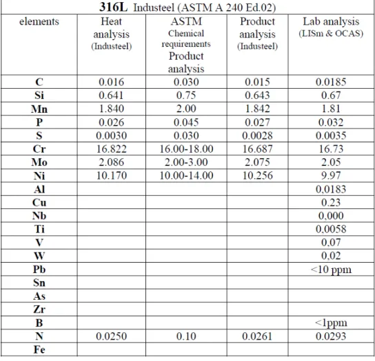
The 316L and T91 steels used in the LEXUR II have been already characterized in FP 6 EUROTRANS project ( DM4-DEMETRA, WP 4.1). The chemical compositions of these materials are given in Table 1 and Table 2.
The 15-15Ti steel were obtained from two different sources. The tubes for fabrication of pressurized tubular specimens were supplied by CEA. The chemical composition is given in Table 3. The rods to fabricate tensile, CT and corrosion specimens were supplied by FzK. However, for the latter material the certificate was not found. Therefore the chemical analysis will be performed and reported later.
ODS 14Cr manufactured by CEA has been chosen to be tested at both temperatures. The scarce availability of other kinds of ODS, such as 9cr, drove this choice.
Coated T91’s. The GESA coating by KIT (metal coating and pulsed laser beam treatment in vacuum on ferritic martensitic matrixes) and the FeAl coating manufactured in Italy by UNITN showed a very good compatibility with flowing HLM. Testing them under irradiation in HLM will give a very important output, in view of the choice of the reference material for the cladding elements.
Ricerca Sistema Elettrico Sigla di identificazione NNFISS - LP3 - 012 Rev. 0 Distrib. L Pag. di 6 22
Table 2. Chemical composition of the T91 OCAS made, all percentages are in weight percent
Table 3. Chemical composition of the 15-15 Ti tubes delivered by CEA, all percentages are in weight percent.
Elements Specification Lab analysis (CEA)
C 0.08-0.10 0.085 Cr 14-16 14.9 Ni 14-16 15.2 Mn 1-2 1.64 Mo 1.3-1.7 1.43 Si 0.7-0.9 0.85 Ti 0.3-0.5 0.37 Nb Cu <0.03 0.042 Al <0.015 0.0135
Co <0.03 0.016
P <500 ppm 420 ppm
B <80 ppm 72 ppm
S <150 ppm 20 ppm
N <150 ppm 89 ppm
6. Type and dimensions of the samples
In LEXUR II 4 pressurized tubes, 8 compact toughness discs, 39 tensile strength specimens and 18 corrosion samples made of T91, 316L, 15-15Ti and ODS 14Cr steels will be irradiated. Two separate compartments for foreseen for corrosion specimens in every capsule: one compartment with low oxygen concentration and one with oxygen saturated conditions. The summary of the specimens per capsule is given in the Appendix I.
The specifications are:
Two types of pressurized tubes will be prepared: with an outer diameter of 6.55 mm and an inner diameter of 5.65 mm (see Figure 1) made of 15-15Ti for irradiation in LBE capsules and with an outer diameter of 8.5 mm and an inner diameter of 7.5 mm (see Figure 1) made of T91 for irradiation in Pb capsules. The tubes and closed with two plugs made from the same material as tubes. These will be filled with argon different pressure to create different hoop stress.
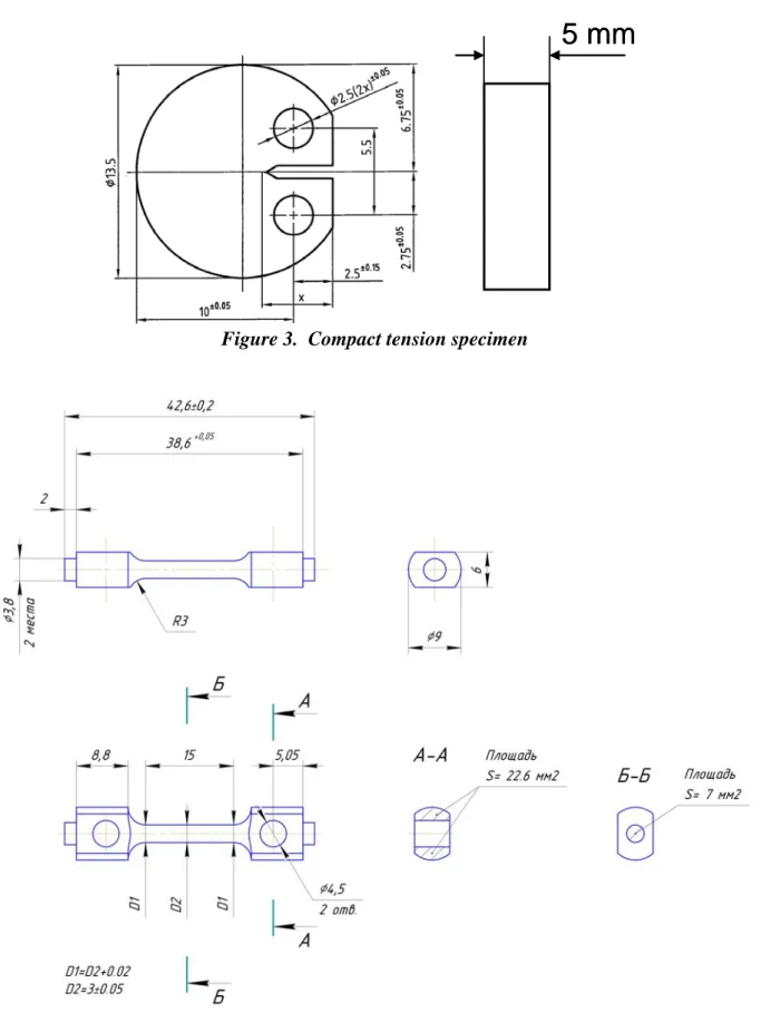
Compact tension discs are discs with a diameter of 13.5mm and a thickness of 5mm (see Figure 2). The CT are pre-cracked and side grooved (fig.3).
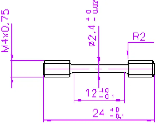
Two types of tensile specimens are fabricated since testing of the irradiated specimens will be performed at two institutes: RIAR and SCK•CEN. The tensile tests at RIAR will be performed in small capsules filled with LBE or Pb. The specimens will be fixed in the grip by pin. The design of those specimens to test at RIAR is shown in Figure 4. The tests at SCK•CEN will be done in an autoclave of LIMETS II set-up where it will be fixed in the grip with a thread. . The design of those specimens to test at RIAR is shown in Figure 5
The corrosion specimens are disks of 5 mm diameter and 2 mm thickness (Figure 6).
The coated specimens shall have the same specifications of the corrosion one.
Ricerca Sistema Elettrico Sigla di identificazione NNFISS - LP3 - 012 Rev. 0 Distrib. L Pag. di 8 22
Figure 1. Pressurized tube specimen for LBE capsules
5 mm
5 mm
Figure 3. Compact tension specimen
Ricerca Sistema Elettrico Sigla di identificazione NNFISS - LP3 - 012 Rev. 0 Distrib. L Pag. di 10 22
Figure 5. Tensile specimen – design SCK•CEN
Ø 5 mm
2 mm
Ø 5 mm
2 mm
7. Irradiation rig and capsules
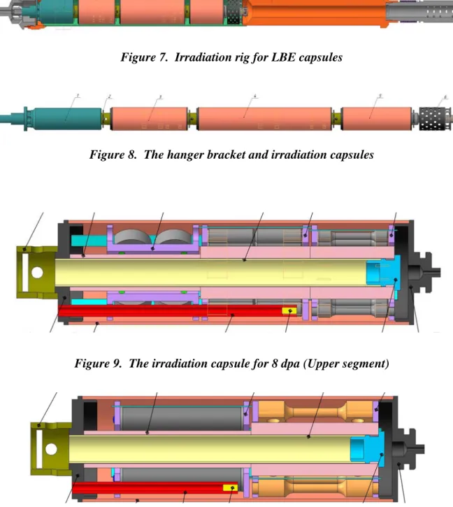
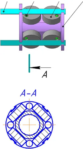
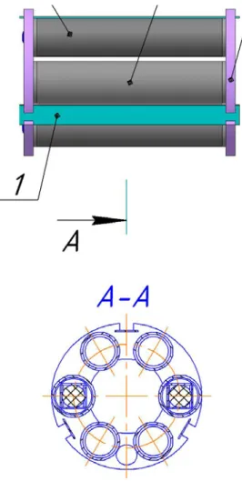
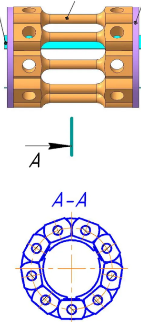
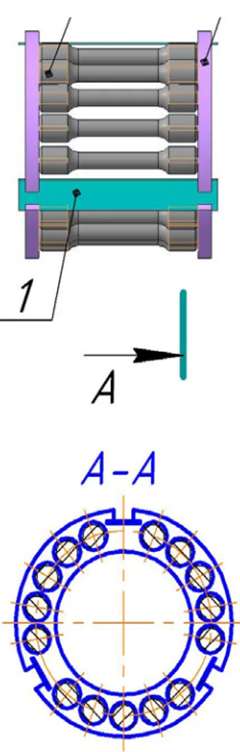
The general specification of irradiation capsule is given in Appendix IV. The preliminary design has been performed and shown in Figure 7 to Figure 15. The design of the irradiation capsules is still to be modified taking into account results of neutronic and heat-transfer calculations in order to reach as homogeneous as possible temperature and dose distributions on the specimens.
Figure 7. Irradiation rig for LBE capsules
Figure 8. The hanger bracket and irradiation capsules
Ricerca Sistema Elettrico Sigla di identificazione NNFISS - LP3 - 012 Rev. 0 Distrib. L Pag. di 12 22
Figure 10. The irradiation capsule for 8 dpa (Bottom segment)
Figure 11. The irradiation capsule for 16 dpa
Figure 13. The cartridge for pressurized tubes and for two compartments with the corrosion specimens
Ricerca Sistema Elettrico Sigla di identificazione NNFISS - LP3 - 012 Rev. 0 Distrib. L Pag. di 14 22
Figure 15. The cartridge for tensile specimens (SCK•CEN design)
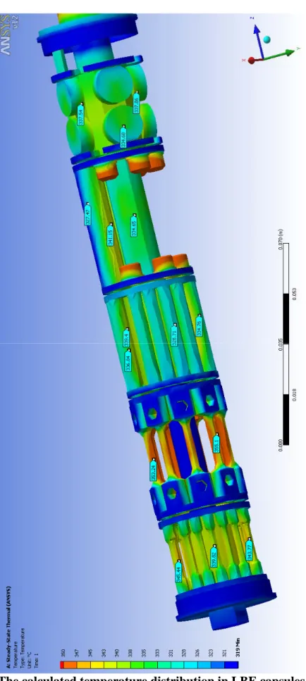
8. Temperature distribution
The preliminary heat-transfer calculations of the LBE capsule for 16 dpa has been performed. The temperature distribution is shown in Figure 16. As one can see the temperature on the specimens varies from 329 to 355 °C. The biggest temperature difference of 14 °C is on the pressurized tubes. The design will be still modified to have more homogeneous distribution in the capsule and on the specimens but high gamma heating of LBE in comparison with the iron based steels and big gradients in the core of fast reactor make this task difficult.
The performance of the heat-transfer calculations for the 500°C capsule in pure Pb is on going.
Ricerca Sistema Elettrico Sigla di identificazione NNFISS - LP3 - 012 Rev. 0 Distrib. L Pag. di 16 22
9. Post –irradiation examination
The specification of the PIE is given in Appendix V. It still can be modified if needed to obtain high quality results.
10. Conclusion: the next steps
After the construction of the specimens test sections and the manufacturing of the various specimens in ENEA workshop, the materiuals will be sent to RIAR, where exposure will start in two instrumenated channels of the BOR60 reactor.
The exposure of the specimens, for both doses, will end by december 2012. The performance of the PIE will give extremely important data of combined effect of radiation and corrosion, at relatively high doses, in Pb.
Ricerca Sistema Elettrico Sigla di identificazione NNFISS - LP3 - 012 Rev. 0 Distrib. L Pag. di 18 22
11. Appendix I: Irradiation capsules content
"350°C LBE 8 dpa" & "350°C LBE 16 dpa" capsules content:
Corrosion specimens low oxygen content compartment
2 x T91 2 x 316L 2 x 15-15Ti
Corrosion specimens saturated oxygen conditions compartment
2 x T91 2 x 316L 2 x 15-15Ti Tensile specimens: RIAR design 3 x T91 3 x 316L 3 x 15-15Ti SCK•CEN design 5 x T91 5 x 316L 5 x 15-15Ti Pressurized tubes: 4 x 15-15Ti CT: 4 x T91 2 x 316L 2 x 15-15Ti
"550°C Pb 8 dpa" & "550°C Pb 16 dpa" capsules content:
Corrosion specimens low oxygen content compartment
2 x T91
2 x ODS 14Cr 2 x T91 coated
Corrosion specimens saturated oxygen conditions compartment
2 x T91
2 x ODS 14Cr 2 x T91 coated
RIAR design 5 x T91 4 x ODS 14 Cr SCK•CEN design 10 x T91 5 x ODS 14Cr Pressurized tubes: 4 x T91 CT: 4 x T91 4 x ODS 14Cr
Ricerca Sistema Elettrico Sigla di identificazione NNFISS - LP3 - 012 Rev. 0 Distrib. L Pag. di 20 22
12. Appendix II: Test matrix at RIAR
Test Irradiation conditions 8 dpa 350°C LBE 16 dpa 350°C LBE 8 dpa 550°C Pb 16 dpa 550°C Pb Tensile tests, 350 °C, air 1x316L 1xT91 1x15-15Ti 1x316L 1xT91 1x15-15Ti Tensile tests, 550 °C, air 1xT91 1xODS 14Cr 1xT91 1xODS 14Cr Tensile tests, 350 °C, LBE 2x316L 2xT91 2x15-15Ti 2x316L 2xT91 2x15-15Ti Tensile tests, 550 °C, Pb 5xT91 4xODS 14Cr 5xT91 4xODS 14Cr Fractography* 2x316L 2xT91 2x15-15Ti 2x316L 2xT91 2x15-15Ti 3xT91 3xODS 14Cr 3xT91 3xODS 14Cr
SEM fractured surface
2x 316L 2xT91 2x15-15Ti 2x316L 2xT91 2x15-15Ti 3xT91 3xODS 14Cr 3xT91 3xODS 14Cr
Optical microscopy, SEM & electron probe on corrosion specimens cross section 2x316L 2xT91 2x15-15Ti 2x316L 2xT91 2x15-15Ti T91 T91ct ** ODS 14Cr T91 T91ct ODS 14Cr Dimension analysis of
pressurized tubes 4x15-15Ti 4x15-15Ti 4xT91 4xT91
*The specimens will be defined after tensile tests, normally one specimen tested in air and one(two) tested in Pb
13. Appendix III: Design and fabrication of irradiation capsules and
rigs
Design of irradiation capsules
Design of rig/capsules for irradiation up to 8 and 16 dpa of the corrosion, tensile, CT and pressurised tube specimens in lead-bismuth eutectic (LBE) at 350°C.
Design of rig/capsules for irradiation up to 8 and 16 dpa of the corrosion, tensile, CT and pressurised tube specimens in molten lead at 550°C.
The target dose should be reached within +-30% and measured dose accuracy should be 10% or better. The target temperature should be reached within +-10°C for the capsules filled with LBE and +-25°C for capsules filled with lead. The accuracy of the measurements of the actual temperatures inside of the capsules during irradiation in the instrumented channel should not exceed +-10°C. The axial gradient in the capsules should not exceed 10°C.
The liquid metal inside of the capsule should be under low oxygen conditions, except small compartment for corrosion specimens, where saturated oxygen conditions should be reached. In order to reach low oxygen conditions the oxygen getters (Mg) provided by ENEA will be placed in the capsules. The conditioned LBE will be provided by SCK-CEN and conditioned lead by ENEA. The oxygen saturated conditions in the separate corrosion specimens compartment(optional) will be provided by placing of PbO (provided by SCK-CEN/ENEA) in the compartment.
The volume of a single capsule should be 100 cm³ or more. The minimum amount of specimen are the following:
Corrosion: 6 Tensile: 12
Pressurized tubes: 8 CT: 4
The exact amount of the specimens of every type and their arrangement in the capsules will be specified during the design of the capsules and should be confirmed by SCK•CEN and ENEA. The design of the capsule should be optimized in order to include as many specimens as possible for irradiation in specified above conditions. The preliminary drawing of the specimens and capsules content are given in Appendix I and Appendix II respectively.
For pressurized tube, SCK•CEN will provide the tube and the two plugs (weld performed at SCK•CEN). Filling with gas and closing the tube will be performed by RIAR. The procedure to check the inside pressure and leak
Ricerca Sistema Elettrico Sigla di identificazione NNFISS - LP3 - 012 Rev. 0 Distrib. L Pag. di 22 22
tightness of the specimens is still to be develop by SCK•CEN with help of RIAR.
Capsule will also contain dosimeters and temperature monitor. It will allow verifying the actual received dose (thermal and fast neutron flux) and the maximum irradiation temperature. This verification will be performed after opening the capsule in the post irradiation examination section.
Fabrication
Fabrication of two capsules for irradiation up to 8 and 16 dpa of the corrosion, tensile, CT and pressurized tube specimens in LBE at 350°C.
Fabrication of two capsules for irradiation up to 8 and 16 dpa of the corrosion, tensile, CT and pressurised tube specimens in molten lead at 550°C.
Fabrication of the rig for irradiation up to 8 dpa of one capsule with LBE at 350 °C and one capsule with molten lead at 550 °C.
Fabrication of the rig for irradiation up to 16 dpa of one capsule with LBE at 350 °C and one capsule with molten lead at 550 °C.
Development of specimens traceability system and loading procedure. The scheme should provide double crosscheck by marking of the specimen and cartogram of the specimens arrangement in the capsules. The marking of the specimens should remain readable after irradiation of the specimens in liquid metal at high temperature.
The thermocouples of class 1 (+/-1.5°C up to 375°C and +/-0.4% from 375°C up to 1000°C) should be used to monitor temperature inside of the capsules. X-ray pictures of every capsule before and the filling with specimens and molten lead/LBE should be done.
Irradiation
Irradiation of the capsule with LBE at 350°C up to 8 dpa. Irradiation of the capsule with LBE at 350°C up to 16 dpa. Irradiation of the capsule with lead at 550°C up to 8 dpa. Irradiation of the capsule with lead at 550°C up to 16 dpa.
The actual temperature in the capsules should be measured during at least one cycle. The estimation of temperature evolution on base of coolant temperature should be performed for all the rigs irradiation cycles.
The level of irradiation dose should be measured after every cycle. At least two neutron fluence monitors should be placed inside of the capsule to ensure correct definition of the final accumulated damage dose.