SW4P.5.pdf CLEO:2016 © OSA 2016
Open-Cavity Spun Fiber Raman Lasers with a Polarized
Output
J. Nuño(1, 2), G. Rizzelli(2), F. Galazzi(2), F. Prieto(3), C. Pulido-De-Torres(2), P. Corredera(2), S. Wabnitz(4), J. D. Ania-Castañón(2) *
1. Laboratoire Interdisciplinaire Carnot de Bourgogne, UMR 6303 CNRS - Université Bourgogne Franche-Comté, 9 avenue Alain Savary, 21078 Dijon, France.
2. Instituto de Óptica “Daza de Valdés”, CSIC (IO-CSIC). C/ Serrano 121 28006Madrid, Spain. 3. Saint Louis University - Madrid Campus, Avenida del Valle 34, 28003 Madrid, Spain. 4. Dipartimento di Ingegneria dell'Informazione, Università di Brescia, via Branze 38, 25123 Brescia, Italy.
*Corresponding author: [email protected]
Abstract: We experimentally study the polarization properties of the outputs of different
open-cavity Raman fiber lasers based on spun fiber and a highly polarized pump, demonstrating controlled output polarization and improved threshold.
OCIS codes: (190.4370) Nonlinear optics, fibers; (140.3550) Laser, Raman; (260.5430) Polarization; (190.5650) Raman
effect
Mirrorless fiber Raman lasers based on a distributed feedback via Rayleigh scattering [1] have attracted a great deal of attention in the last decade, as their lasing efficiency and beam quality are comparable to those of standard cavity lasers. Recently, in order to govern the state of polarization (SOP) of the laser output radiation and increase its efficiency, the use of polarized pumps and polarization-maintaining (PM) fiber have been proposed [2-4]. Here, we propose the complete control of the SOP of the output by means of the use of spun fiber. These fibers are created by rotating the fiber preform during the drawing processes, producing a fiber with a negligible average polarization mode dispersion (PMD).
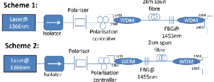
The schematic setup designed for our experiment consists of a 2 km piece of spun fiber pumped by a CW fiber laser at 1366nm, able to produce up to 38dBm. The pump is polarized by a polarizer prism, which inserts losses equal to approximately 3.6 dB, and injected into the fiber on one end, whereas a fiber Bragg grating (FBG), centered at 1454.5 nm, is initially situated at the opposite fiber end (scheme 1) or the same end (scheme 2). These two options are depicted in figure 1.
Figure 1 - Scheme of the experimental setup for an open cavity laser (upper case) with a FBG at the end (lower case) with a FBG at the beginning.
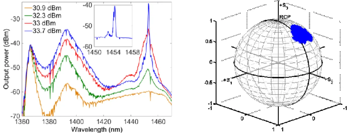
The evolution of the forward-propagating (co-pumped) output spectrum for scheme 1, measured on the right side, is plotted in figure 2(a). We observe the generation of a supercontinuum at 1393 nm. When the open cavity is pumped with the depolarized pump (i.e., without the polarizer prism), this supercontinuum absorbs most of the energy, hence preventing the cavity from lasing for injected pump powers up to 35.5 dBm. The situation changes if we switch to the highly polarized pump. The evolution of the output spectrum can be divided in two stages. For pump powers below 33.5 dBm, the performance is dominated by XPM and parametric effects. The power of the supercontinuum, mentioned above, is increased with the pump power. For pump powers higher than 32 dBm, a new peak appears at 1453 nm growing until pump power reaches 33.5 dBm at which both peaks (1393 nm and 1453 nm) begin to decrease, as Raman effect becomes dominant and the device begins to lase at 1453 nm. Moreover, the power of the signal at 1393 nm is also reduced when the pump power is increased. Remarkably, lasing in this forward-propagating component occurs at the Raman gain peak, which does not fully overlap with the FBG wavelength. This result suggests that lasing is in this case independent on the presence of the FBG. This premise is confirmed by moving to scheme 2, in which the power threshold is similar, although the FBG is situated at the pumping end.
SW4P.5.pdf CLEO:2016 © OSA 2016
Although the lasing signal is not always fully polarized, its degree of polarization (DOP) is high. When the SOP of the pump is managed by a polarization controller (PC), the DOP fluctuates between 75% and 100% for scheme 1 and between 65% and 95% for scheme 2. The SOP is also dependent on the SOP of the pump and it moves along the complete Poincare sphere, following that of the pump. This is to be expected, as the SOP of the generated signal is attracted to the SOP of the pump and these are maintained along propagation thanks to the low PMD of the spun fiber. For comparison, the experiments were redone for a 3-km SMF fiber, obtaining lower polarization attraction, with output signal DOPs as low as 40%. Furthermore, the improvement of the threshold is only 0.2 dBm in the SMF despite its lower fiber losses and higher gain coefficient than the spun fiber.
Figure 2 (a) Spectrum of the co-propagating output for the scheme 1. In the subplot, spectrum of the counter-propagating signal. (b) Poincare sphere of the 1454.5 nm output signal in the configuration 1.
Secondly, we analyze the properties of the signal counter-propagating with the pump. The output spectrum, measured on the left side of scheme 1, can be seen in the small subplot of figure 2(a). Here we observe two signals at 1453 nm and 1454.5 nm. The 1453 nm signal corresponds to the Rayleigh backscattering of the forward-propagating lasing signal while the 1454.5 nm corresponds with the amplified signal reflected by the FBG. In this direction the lasing threshold is higher because the polarization attraction is less efficient in the counter-propagating direction [5], and lasing at 1453 nm is not achievable with the available pump powers. The polarization properties of the 1454.5nm signal are more surprising. As it is shown in the Poincare sphere, plotted in figure 2 (b), the DOP remains extremely close to 100% for any SOP of the pump, with a well-defined SOP that is independent from that of the pump. This effect is comparable with the performance of the omni-polarizer [6] where the interaction between the co-propagating signal and the counter-propagating one induces a preferent polarization output. In our experiment, the effect is also influenced by the different interaction of Raman pump with the co and counter-propagating Stokes and the low PMD of the spun fiber. Repeating the same measurements for the SMF, the DOP of the backward-propagating output signal varies between 30% and 85% depending on the configuration of the PC, and the SOPs are distributed over a much broader range in the Poincare sphere than in the spun fiber case, as it can be expected due to its much higher PMD.
To summarize, we have analyzed the performance of two open-cavity Raman fiber lasers based on spun fiber and a polarized pump, studying the polarization properties of its laser outputs and their relation to those of the pump.. Remarkably, the efficiency of this configuration is comparable to that of a longer configuration based on SMF, but also the DOP of its output is higher. Forward output power is independent of the position of the FBG and its wavelength corresponds with the maximum of the Raman gain. In the backward-propagating output, the FBG back-reflected signal presents an extremely high DOP, with a fixed SOP independent of the pump SOP.
References
[1] S. K. Turitsyn, S. A. Babin, A. E. El-Taher, P. Harper, D. V. Churkin, S. I. Kablukov, J. D. Ania-Castanon, V. Karalekas, and E. V. Podivilov, Nat. Photonics 4, 231 (2010).
[2] H. Wu, Z N Wang, D. V. Churkin, I. D. Vatnik, M. Q. Fan, and Y. J. Rao, Laser Phys. Letters 12, 015101 (2015). [3] X. Du, H. Zhang, H. Xiao, P. Zhou, and Z. Liu, Photonics Res. 3, 28 (2015).
[4] E. A. Zlobina, S. I. Kablukov, and S. A. Babin, Opt. Lett. 40, 4074-4077 (2015).
[5] VV Kozlov, J Nuño, JD Ania-Castanón, S Wabnitz, J. Lightwave Technol. 29 (3), 341-347 (2011).