Departament de Química Física
Dra. Núria Cinca Luis
Centre de Projecció Tèrmica
Treball Final de Grau
Anodizing of Titanium coatings with different roughnesses.
Anoditzat de recobriments de Titani de diferents rugositats.
Carlos Santiveri Carrera
Aquesta obra esta subjecta a la llicència de: Reconeixement–NoComercial-SenseObraDerivada
C
ONTENTS
1.
S
UMMARY 32.
R
ESUM 53.
I
NTRODUCTION 73.1. Titanium 7
3.2. Micro-nano roughness surface treatments 8
3.2.1. Grit-blasting 8
3.2.2. Acid etching 8
3.2.3. Thermal spray 9
3.2.3.1. Vacuum plasma spray
9
3.2.3.2. Cold gas spray
10
3.2.4. Anodization 10
3.3. TiO2 nanotubes 11
3.3.1. Synthesis methods 11
3.3.2. Properties 13
3.4. Applications 14
3.4.1. Environmental and energy applications 14
3.4.2. Biomedical applications 15
4.
O
BJECTIVES 165.
E
XPERIMENTAL SECTION 175.1. Material and equipment 17
5.2. Preparation of the experimental setup 17
5.3. TiO2 nanotubes synthesis 19
5.4. Characterization 19
6.
R
ESULTS AND DISCUSSION21
6.1. Previous work conclusions 21
6.2.1. ETG - 5% wt H2O and NH4F 0,2% wt solution 23
6.2.2. ETG - 7,5% wt H2O and NH4F 0,2% wt solution 25
6.3. Two-step anodization 28
6.3.1. Anodizations at 50 V and 1800 s 36
6.3.2. Anodizations at 60 V and 900 s 38
6.4. Different roughness substrates 40
6.4.1. Roughness characterization 40
6.4.2. Nanotubes synthesis 41
6.4.3. Coloured rough titanium 47
6.4.4. Contact angle 49
7.
C
ONCLUSIONS51
8.
R
EFERENCES AND NOTES53
A
PPENDICES 55Appendix 1: Roughness characterization basis 57
1.
S
UMMARY
Titanium is a metallic material that has been studied for decades because of its interesting chemical, physical and biological features. More specifically, there have been numerous efforts in studying how the formation of ordered titanium oxide (TiO2) structures on its surface affects
its properties (optical, catalytic, electrical, biocompatibility...). These structures can be obtained by several techniques, such as from anodization. This electrochemical technique allows obtaining a controlled oxide layer with the desired thickness and structure, and if certain parameters are well defined (electrolyte, potential applied, time...), ordered nanostructures. This range of structures can be obtained using a power supply controlled by a computer and a simple experimental system.
The aim of this project is the electrochemical production of titanium oxide nanotubes and its characterization, as well as creating a hierarchical structure (macromicronano) to see which impact has the roughness of the substrate in the bioactivity and biocompatibility of this material.
2.
R
ESUM
El Titani es un material metàl·lic que ha estat molt estudiat durant les últimes dècades degut a les seves interessants propietats tant químiques, físiques com biològiques. Més concretament, s'han posat nombrosos esforços en l'estudi de com afecta a les seves propietats (òptiques, catalítiques, elèctriques, reactivitat, biocompatibilitat...) la formació d'estructures ordenades d'òxid de titani (TiO2) a la seva superfície. Aquestes estructures es poden obtenir mitjançant
nombroses tècniques, com per exemple a partir de l'anodització. Aquesta tècnica electroquímica permet l'obtenció controlada d'una capa superficial d'òxid amb l'estructura i gruix desitjats, i si es defineixen bé certes condicions (com per exemple l'electròlit, el potencial, el temps...), nanoestructures ordenades. Aquest ventall d'estructures es poden obtenir utilitzant una font d'alimentació controlada per un ordinador i un sistema experimental molt senzill.
L'objectiu d'aquest projecte és la producció electroquímica de nanotubs d’òxid de titani i la seva caracterització, així com obtenir una estructura jeràrquica (macromicronano) per veure quin impacte té la diferent rugositat del substrat en la bioactivitat i biocompatibilitat d'aquest material.
3.
I
NTRODUCTION
3.1.
T
ITANIUMTitanium is encompassed in an interesting group of metals known as valve metals, like for example Al, Zr, Hf, Ta, W, and alloys like TiZr, TiZrNb or Ti6Al7Nb[1]. A valve metal could be
defined as a metal that spontaneously forms an oxide layer on its surface when exposed to air/water that works as protection and generally has good corrosion resistance properties. This phenomenon is also known as metal passivation. In the Titanium case, this natural oxide layer may consist of three different crystal structures: rutile, anatase and amorphous. It is possible to go from the amorphous phase to the crystalline phases rutile and anatase with thermal treatments [1, 2].
Due to its physical and chemical characteristics (strength-to-weight ratio, high melting point, tensile strength, low thermal and electrical conductivity, excellent resistance to corrosion thanks to passivation, etc.), Titanium and TiO2 have been widely used in many fields, as for example in
pigments, additives and coatings, aerospace and marine, biomedicine, industrial equipment, architecture, jewellery, nuclear waste storage...
As a biomaterial, Titanium and its alloys are classified as biologically inert materials, which means that they remain essentially unchanged when implanted into human bodies. This is no doubt a result of their excellent corrosion resistance. They have been used for dental implants, stents, orthopaedic screws, artificial joint components, orthodontics and others in the last decades, so it has a remarkable biofunctionality that could be enhanced with more study [3]. In this study, the intention is to take advantage of the nanotechnology, which works with the surface modification at nanoscale level to improve physical, chemical, biological and medical properties.
3.2.
M
ICRO-
NANO ROUGHNESS SURFACE TREATMENTSThere are several techniques that could be used to perform treatments in a metal surface. The objective of those treatments is to modify the roughness of the material's surface at micro-nanoscale, so it is possible to improve its properties. For example, in titanium and its alloys, various surface treatment techniques such as acid-etching, grit-blasting, anodization, plasma-spraying and chemical modifications have been studied to improve biological characteristics that promote osseointegration and bone formation [4].
3.2.1. Grit-blasting
This method consists in blasting the implants with hard ceramic particles, i.e. Al2O3, TiO2
(Fig. 1). The blasting material is often embedded into the implant surface and residue remains even after ultrasonic cleaning, acid passivation and sterilization. In some cases, these particles have been released into the surrounding tissues and have interfered with the osseointegration of the implants.
Figure 1. Scanning electron micrograph of sandblasted implant surface. *(from Astratech TiOblastTM,
France) [5].
3.2.2. Acid etching
Acid etching involves immersing a metal substrate in an aqueous acid solution to remove a loose layer of oxide from its surface (Fig. 2). The particular acid used depends upon the metal and type of oxide being treated.
Figure 2. Scanning electron micrograph of acid-etched implant surface. *(from Straumann
AG, Switzerland) [5].
3.2.3. Thermal spray
Thermal spraying techniques are coating processes in which materials are sprayed onto a surface, being able to provide thick coatings (approx. thickness range is 20 m to several mm, depending on the process and feedstock), over a large area at high deposition rate as compared to other coating processes. Coating materials available for thermal spraying include metals, alloys, ceramics, plastics and composites. There are several variations of thermal spraying. Usually, melted (or heated) materials are sprayed onto a surface, where the "feedstock" (coating precursor) is heated by electrical (plasma or arc) or chemical means (combustion flame). When the materials sprayed are heated or melted, we find plasma spraying, detonation spraying, wire arc spraying... Moreover, there are other variations that do not heat a lot or melt the materials, like vacuum plasma spraying, warm spraying, cold spraying...
3.2.3.1. Vacuum Plasma Spraying
Vacuum plasma spraying (VPS) is a technology for etching and surface modification to create porous layers with high reproducibility. This surface engineering can improve properties such as frictional behaviour, heat resistance, surface electrical conductivity, or make materials hydrophilic or hydrophobic. The process typically operates at 39–120 °C to avoid thermal damage. Plasma processing is done in a controlled environment inside a sealed chamber at a
medium vacuum, around 13–65 Pa. It is used for coating medical Titanium or Titanium alloys implants, but because it works in vacuum conditions its a very expensive technique (Fig. 3).
Figure 3. Scanning electron micrograph of TPS implant surface. * (from Cam Implants BV,
The Netherlands) [5].
3.2.3.2. Cold Gas Spray
In Cold Gas Spray (CGS), particles are accelerated to very high speeds by a carrier gas. Upon impact, solid particles with sufficient kinetic energy deform plastically and bond mechanically to the substrate to form a coating. The critical velocity needed to form bonding depends on the material's properties, powder size and temperature. Metals, polymers, ceramics and composite materials can be deposited using cold spraying. This process is of especial interest since denser coatings without interparticle oxidation are obtained with respect to the conventional Thermal Spray processes. Specially, for oxygen-sensitive materials such as titanium, it offers a more cost-effective route in front of VPS.
3.2.4. Anodization
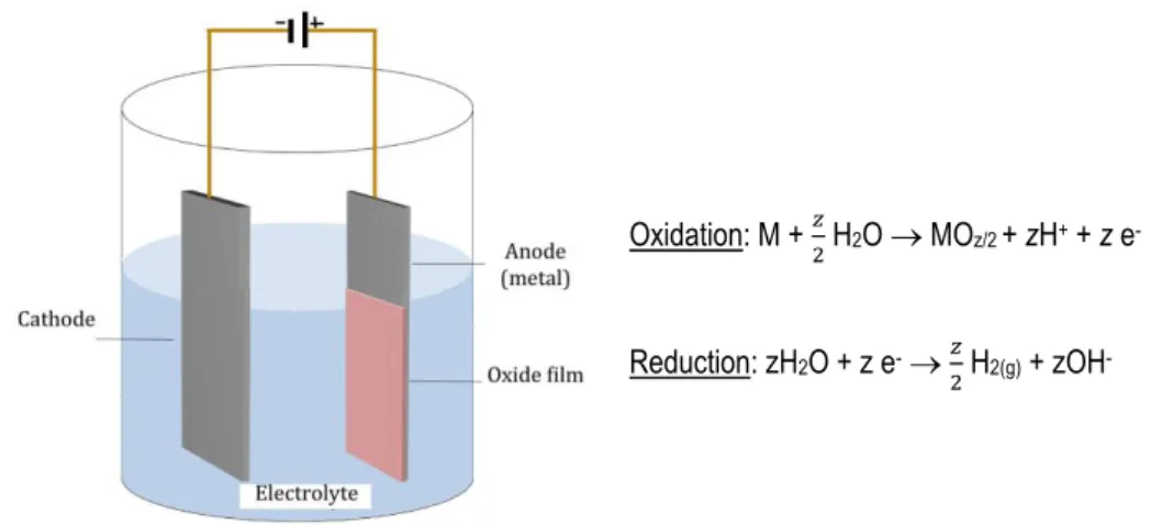
Anodization is an electrochemical process that is used to increase the thickness of the natural oxide layer on the surface of a metal. The anodizing process is very simple and can be held in a simple electrochemical cell (Fig. 4). In the anode takes place the oxidation of the metal, and in the cathode occurs the reduction process.
Figure 4. Scheme of an electrochemical anodizing cell.
3.3.
T
IO
2 NANOTUBESDifferent types of highly ordered TiO2 structures can be obtained, such as nanowires,
nanorods, nanotubes, nanofilms...
Nanotubes are of great interest due to their high surface to volume ratio and size-dependent properties. With the discovery of carbon nanotubes and their interesting properties, the quest of synthesizing nanotubular structures of other substances has been stimulated. Several recent studies have indicated that Titanium oxide nanotubes have improved properties compared to any other form of Titanium for applications in photocatalysis, sensing, photoelectrolysis, photovoltaics and others [6].
3.3.1. Synthesis methods
Titanium oxide nanotubes and nanotube arrays have been produced along the past decades by a variety of methods, including deposition into nanoporous alumina template, sol-gel transcription using organo-sol-gelators as templates, seeded growth, hydrothermal processes... [6]. However, the best results with the most remarkable properties obtained are highly ordered nanotube arrays made via anodization of titanium in fluoride-based baths, with precise control of the dimensions.
Oxidation: M + 𝑧
2 H2O MOz/2 + zH+ + z e
-Reduction: zH2O + z e-𝑧
Using organic electrolyte systems, such as ethylene glycol, almost ideal hexagonally arranged tube layers could be grown to a thickness of several hundreds of m [2].
Anodic oxidation leads to the formation of a compact oxide layer following these equations in the anode: M Mz+ + z e- (1) M + 𝑧2 H2O MOz/2 + z H+ + z e- (2a) Mz+ + z H2O M(OH)z + z H+ (2b) M(OH)z MOz/2 + 𝑧 2 H2O (3)
At the same time, the Hydrogen reduction reaction takes place in the cathode:
z H2O + z e-𝑧
2 H2(g) + zOH- (4)
The presence of fluorides in the electrolyte strongly affects the anodization process, as fluorides form water-soluble [TiF6]2- species. In one hand, complexation occurs with Ti4+ ions
that are ejected at the oxide–electrolyte interface [equation (1)], and in the other hand by chemical attack of the formed TiO2:
Ti4+ + 6F- [TiF6]2- (5)
TiO2 + 6F- + 4H2O [TiF6]2- + 2H2O (6)
At very low or high fluoride concentrations, the formation of the nanotubes doesn't take place properly. If the concentration is very low, there is no complexation of the titanium to form [TiF6]2- and a compact oxide layer is formed. In the other hand, if the fluoride concentration is
For the reasons mentioned above, in an organic solvent the recommended fluoride concentration range is about between 0.05 wt % and 0.5 wt %, because at these fluoride levels, it exists equilibrium between the formation of titanium oxide nanotubes at the metal-oxide interface and the Titanium oxide dissolution at the oxide-electrolyte interface [2, 7].
3.3.2. Properties
Transition metal oxides possess a wide range of functional properties based on their optical, electrical and chemical behaviour (including biocompatibility). In their nanostructured form, the field of potential applications of these materials is broadening even further.
TiO2 is an n-type semiconductor that has, depending on its crystal structure, a band gap
energy of 3.2 eV for anatase, 3.0 eV for rutile, or 3.2–3.5 eV in its amorphous state. Due to the crystal structures differences, it has been reported that anatase is more active photocatalytically [8]. In the energy field, the crystal structure and also the presence of surface defects and vacancies that provide additional states in the band gap are strongly related with the electrochemical properties [9]. Because of the relative position of the band edges and a comparably long electron lifetime, TiO2 are the basis of numerous functional applications, as for
example into dye-sensitized conversion of solar to electrical energy.
Another special feature of TiO2 and other transition metal oxides is the ability to intercalate
small ions into the lattice. The insertion process is accompanied by a reduction process, TiO2 +
Y+ + x e- YTiO2, where Y+ is a charged small ion (i.e. H+ or Li+), forming Ti3+ species leading
to a drastic change in the electronic and optical properties of the material [2, 9].
Modification of the TiO2 nanotubes is mainly carried out by heat treatments, introducing
other elements or by tube-wall decoration. The aim is to make the material suitable for various applications based on specific electrical, optical, or chemical properties. In view of electronic properties, annealing to a different crystalline structure changes the conductivity and lifetime of charge carriers, while active doping or band gap engineering by introducing other elements targets decreasing the optical band gap, thus enabling a visible-light photoresponse. Particle decoration is often used to increase surface catalytic effects [2].
Furthermore, the material has a high corrosion and photocorrosion resistance, shows a high biocompatibility (TiO2 nanostructures are known to have and encouraging effect on cell
behaviour such as adhesion, migration, survival and differentiation) [10, 11], non-toxicity and a comparably low price, making it a very interesting option for many applications.
3.4.
A
PPLICATIONSThanks to the improvement of the equipment and techniques over the past years, it has been possible to investigate and perform many applications that use TiO2 nanostructures.
Depending on the crystal structure, the nanotube diameter and length, and other parameters, the applications can vary significantly. In general terms, nanotubular TiO2 applications can be
divided into biomedical and environmental-energy applications.
3.4.1. Environmental and energy applications
Thanks to the n-type semiconductor properties and its capacity to intercalate small ions into lattice, TiO2 has an elevated number of applications in energy and environment fields:
A new type of solar cell, known as dye-sensitized solar cell, uses a TiO2 particle film as the
photoanode, which has a great effect on light conversion efficiency. Dye-sensitized solar cells [12] consist in a dye that absorbs in a wide visible range (350-950 nm) and excites the electrons from the HOMO to the LUMO, followed by a quick injection of the excited electron to the conduction band of TiO2. Those types of solar cells are a relatively low cost technology and
have achieved an overall light-to-electricity conversion efficiency of over 10.6%.
TiO2 is a very photocatalytically active material for the decomposition of organic materials.
In water photolysis [6, 13], H+ and e- can react with H2O to form H2 and O2; that means direct
splitting of water can be achieved. Due to light scattering within a porous structure, incident photons are more effectively absorbed than on a flat electrode.
In other fields, TiO2 can also be applied in gas sensors [14]. Hydrogen sensors can be
viewed as one of many enabling steps on the path to a hydrogen economy, thus are of great scientific and practical importance. The demand for a highly sensitive, selective and stable hydrogen sensor has increased in recent years due mainly to the continued and growing importance of hydrogen in fuel cell applications.
3.4.2. Biomedical applications
Titanium and its alloys are widely used in biomedical applications like orthopaedics or dentistry due to their good biocompatibility, and about 40% of today's biomedical implant materials are based in Titanium or Titanium alloys [2].
In dental surgery, TiO2 nanotubes obtained by anodization in orthodontic Ti miniscrews are
believed to improve osseintegration. Various surface modifications have been investigated in dental implants, such as chemical coating, sandblasting, acid etching and anodic oxidation to fabricate porous surfaces [11]. Several investigations in dental and orthopaedic implants, reported that anodized titanium implants showed rougher surface and higher bone-to-implant contact than non-anodized implants. In addition, some studies [10, 15] suggest that Titania nanotubes with a diameter between 15-30 nm have a better interaction with cells, and higher diameters (between 70-100 nm) provoke higher rate of cell apoptosis. Because of that, resultant TiO2 nanotube structures are known to have an encouraging effect in adhesion, migration,
proliferation and survival of cells [3, 4, 10, 11, 16].
The geometry of the TiO2 nanotube arrays suggests that the material may be used as a
drug-delivery capsule. Thanks to the possibility of controlling the nanotube diameter and using other processes as support, it is possible to coat the nanotubular structures with infection-reducing agents, anti-inflammatory drugs, etc. [3]. An even more elaborated filling and release mechanism was introduced by Song et al. [17], who created amphiphilic tube layers involving hydrophobic caps that doesn't allow water to enter into the tubes unless opened by a photocatalytic interaction. Once the hydrophobic layer is removed, body fluids enter and wash the drugs loaded within the tubes. This can be used for example in cancer and tumour therapy.
In addition, TiO2 nanotubes can be used as blood clotting and antibacterial agent. The fact
of creating coatings on surgical tools and as well on artificial bone and dental implants are of great importance in the blood and tissue compatibility. Titania nanotubes help to retain the natural forms of proteins and improve the adhesion of bone and stem cells, and furthermore these surfaces exhibit very low immunogenicity, provoking low levels of monocyte activation and cytokine secretion. A specific application could be the use of gauze bandage surfaces coated with TiO2 nanotubes to accelerate the rate of blood clot formation and the strength of the
4.
O
BJECTIVES
The aims of the present study are focused in bio-applications. For that reason, the main objective is to obtain small diameter TiO2 nanotubes. To achieve that, it is necessary to optimize
the current conditions studied in order to acquire the ability to control the tube porous geometry to ensure the best biocompatibility possible.
In the second stage, the intent of the research is to anodize titanium surfaces of different roughness and see how affects the nanotubes formation and growth.
5.
E
XPERIMENTAL SECTION
5.1.
M
ATERIAL AND EQUIPMENTThe products described in Table 1 and the equipment described in Table 2 are required for the research work.
Product Purity [%] Quantity Brand
Titanium foil 0,25 mm 99,7 1 Sigma-Aldrich
Titanium foil 0,127mm 99,7 1 Sigma-Aldrich
Ethylene glycol 99,8 3L Sigma-Aldrich
NH4F ≥ 98 100 g Sigma-Aldrich
Stainless steel electrode AA316
x1 circular x2 flat
Table 1. List of products.
Equipment Function
DELTA ELEKTRONIKA SM 400-AR-4 Power supply
LabVIEW 10.0 Data logging
Table 2. List of equipment.
5.2.
P
REPARATION OF THE EXPERIMENTAL SETUPThe experimental setup consists in an anode and a cathode placed into a plastic vessel containing the working electrolyte (Fig. 5).
Figure 5. Experimental setup for anodizing process.
The anode is a piece of titanium (Fig. 6a). The cathode consists in a flat piece of steel that can be placed in one or both sides of the recipient, depending on which of the sample surface has to be anodized (Fig. 6b).
Figure 6. Anode (a) and cathode (b) used for the processes.
The power supply used is the DELTA ELEKTRONIKA SM 400-AR-4 (Fig .7), that registers the time, applied potential and intensity measurements for the posterior data treatment.
Figure 7. Power supply DELTA ELEKTRONICA SM 400-AR-4
5.3.
T
IO
2 NANOTUBES SYNTHESISAll the nanotubes syntheses have been performed with ETG (ethylene glycol) based electrolyte. Several electrolytes have been tested in order to study how different parameters affect the nanotubes geometry and growth. All the electrolytes were prepared using Millipore water.
In the coloured rough titanium, a water based electrolyte with 2,5% wt NH4F has been used.
During the procedure, several Titanium samples have been used. In the first stage, flat samples of 1x5 cm of different thickness (Ti-0,25 mm and Ti-0,127 mm) have been anodized over a surface area between 5 and 7 cm2. In the second stage, cold-gas-sprayed samples of
different roughness were used.
Titanium samples were cleaned with a pre-treatment consisting in eliminating all the organic matter through sonication and degreased in ethanol and then dried with hot air before anodizing. Once the anodization is completed, the Titanium sample is washed with Millipore H2O and dried with hot air.
In some samples, a two-steps anodization process has been carried out. In those cases, after the first anodization, the elimination of the formed oxide layer have been performed by sonication in H2O2 (33%), washing with Millipore water, sonication and degreasing in ethanol
and then drying with hot air before the second anodization. Once the second anodization is completed, the titanium sample is washed with Millipore H2O and dried with hot air.
5.4.
C
HARACTERIZATIONThe characterization of the titanium oxide nanotubes arrays was carried out with the field emission scanning electron microscope (FE-SEM) JEOL JSM-7100F. Compared to a SEM, a FE-SEM microscope uses a source of e- that provides very focused high and low energy
beams, what greatly improves the spatial resolution and produces clearer, less electrostatically distorted images. The high resolution of a FE-SEM microscope was necessary in order to observe the nanotube morphology at high magnification.
The surface characterization of different roughness Titanium samples has been carried out with Leica Map DCM 3D confocal microscope (see Appendix 1).
To measure the contact angle, a custom made goniometer with imageJ software program has been used, performing static measurements (see Appendix 2).
Experiment identifications are not arbitrary, they have been labelled according to the following: First symbol (letter) corresponds to the used solution (Table 3).
Letter Meaning 1a ETG - 2,5% wt H2O and 0,4% wt NH4F a ETG - 5% wt H2O and 0,2% wt NH4F b ETG - 7,5% wt H2O and 0,2% wt NH4F c ETG - 2,5% wt H2O and 0,2% wt NH4F d ETG - 2,5% wt H2O and 0,5% wt NH4F
Table 3. Experiments letter identification.
After the first symbol a number continues, which represents the applied voltage, followed by a hyphen and another number, the anodization time in seconds. For the two-step anodized samples, first numbers correspond to the process mentioned above, and the following symbols represent the re-anodization, the applied voltage and the anodization time.
For example, sample c60-3600re20-7200 would be read as: first anodization performed with ETG - 2,5% wt H2O and 0,2% wt NH4F solution at 60 V for 3600 s, with a re-anodization at 20 V
for 7200 s. In some experiments a second letter appears (i.e. as60-1800); this is because the experiment has another purpose different from the first letter experiments, but the used solution is the same.
6.
R
ESULTS AND DISCUSSION
6.1.
P
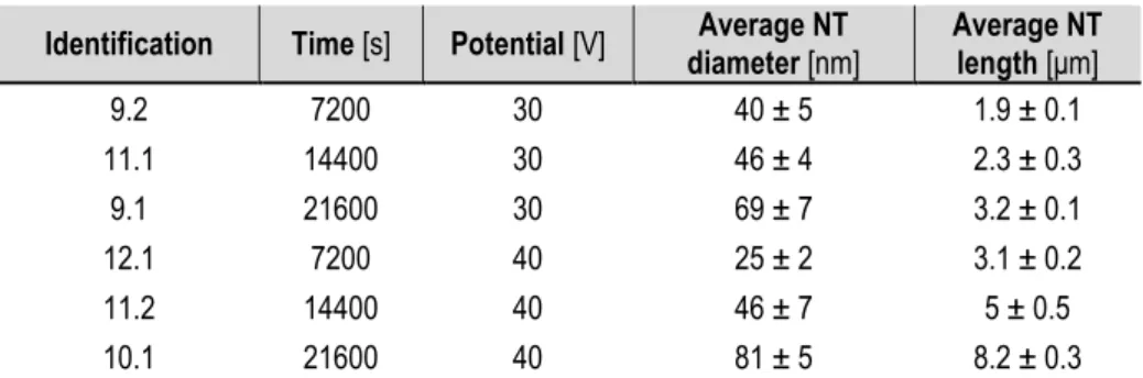
REVIOUS WORK CONCLUSIONSThis experimental project is a continuation of Ivan Pacheco Bubí's work [19]. On that project, first attempts to produce nanotubes took place, and several anodizing parameters were tested (anodization time, potential applied, agitation, potential ramp...) in order to find the best electrochemical conditions to obtain well-defined nanotubes with controlled cell geometry. All the nanotube synthesis were carried out with an ETG based electrolyte with 2,5% wt H2O and
0,2% wt NH4F. In Table 4 some of the results obtained with the best found conditions are
collected.
Identification Time [s] Potential [V] diameter [nm] Average NT Average NT length [μm]
9.2 7200 30 40 ± 5 1.9 ± 0.1 11.1 14400 30 46 ± 4 2.3 ± 0.3 9.1 21600 30 69 ± 7 3.2 ± 0.1 12.1 7200 40 25 ± 2 3.1 ± 0.2 11.2 14400 40 46 ± 7 5 ± 0.5 10.1 21600 40 81 ± 5 8.2 ± 0.3
Table 4. Results obtained with best electrochemical conditions found with ETG - 2,5% wt H2O and 0,2% wt NH4F electrolyte.
Some of the conclusions obtained were, in one hand, that the nanotube length is proportional to the anodization time and the applied potential (current density) due to the fact that more electric load has been transmitted to the sample. In the other hand, the pore diameter increases with time, probably because the sample is more time in contact with the fluoride electrolyte, but also it depends on the applied potential and the fluoride concentration. An
experimental fact observed, was that at low applied potentials (a determining parameter to produce small diameters) a solid oxide layer was present on the surface, so higher potentials were needed in order to obtain opened tubes.
6.2.
S
TUDY OF WATER CONCENTRATION EFFECTTo continue with the previous work, it is necessary to study how certain factors of the solution affect the nanotubes synthesis. On the first stage it has been decided to increase the water content to 5% wt.
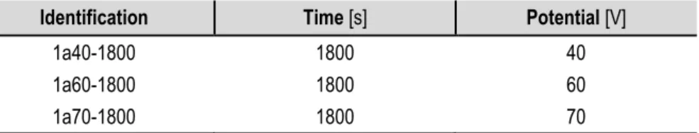
Beforehand, some first attempts (Table 5) were made with a 2,5% wt H2O and 0,4% wt
NH4F ETG based electrolyte solution in order to get used to the equipment.
Identification Time [s] Potential [V]
1a40-1800 1800 40
1a60-1800 1800 60
1a70-1800 1800 70
Table 5. First anodization attempts with ETG - 2,5% wt H2O and 0,4% wt NH4F solution.
Figure 8 illustrates the Titania nanotube morphologies of sample 1a70-1800 through the FE-SEM micrographs.
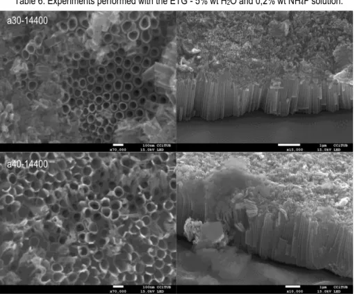
6.2.1. ETG - 5% wt H2O and NH4F 0,2% wt solution
Next electrolyte prepared has been an ETG based electrolyte with 5% wt H2O water content
and 0,2% wt NH4F fluoride content, and the corresponding experiments are found in Table 6. It
was decided to check if current density curves of anodizing time and potential applied were similar to the obtained in the past working solution. (2,5% wt H2O and NH4F 0,2% wt)
Identification Time [s] Potential [V] Average tube diameter [nm] diameter [nm] Average hole
a30-14400 14400 30 111 ± 8 62 ± 4
a40-7200 7200 40 - -
a40-14400 14400 40 142 ± 6 79 ± 4
a50-7200 7200 50 - -
a50-14400 14400 50 - -
Table 6. Experiments performed with the ETG - 5% wt H2O and 0,2% wt NH4F solution.
Figure 9. FE-SEM top and cross sectional view of anodized samples with ETG - 5% wt H2O
and 0,2% wt NH4F electrolyte.
a30-14400
At different anodization times the current density curves have the same shape and values for each potential applied because they are made in the same conditions (Fig. 10 and 11).
Figure 10. Time evolution of current density at 40V.
Figure 11. Time evolution of current density at 50V.
At different applied potentials, the current density curves have the same shapes but the final stationary and initial values are proportional to the applied potential (Fig. 12). This behaviour is expected, because the increase of the applied potential is traduced in an increase of current transfer that maximizes the anodization process.
0 5 10 15 20 0 2500 5000 7500 10000 12500 15000 Cu rr ent d ens it y (m A/cm 2) Time (s) a40-14400 a40-7200 0 5 10 15 20 25 0 2500 5000 7500 10000 12500 15000 Cu rr ent d ens it y (m A/cm 2) Time (s) a50-14400 a50-7200
Figure 12. Time evolution of current density at different applied potential.
At intermediate potentials (30-50V) there is a good adherence and a uniform oxide layer is obtained (Fig. 13).
Figure 13. Sample images of uniform oxidation at 30, 40 and 50V for 14400 s.
6.2.2. ETG - 7,5% wt H2O and NH4F 0,2% wt solution
This electrolyte is an ETG based electrolyte with 7,5% wt H2O water content and 0,2% wt
NH4F fluoride content (water concentration has raised from 5% wt to 7,5% wt), and experiments
in Table 7 were carried out.
Identification Time [s] Potential [V] Thickness [mm] diameter [nm] Average hole
bP40-1800 1800 40 0,127 -
b40-1800 1800 40 0,25 -
b40-14400 14400 40 0,25 95 ± 4
Table 7. Experiments performed with the ETG - 7,5% wt H2O and 0,2% wt NH4F solution.
0 5 10 15 20 25 0 2500 5000 7500 10000 12500 15000 Cu rr en t d en si ty (mA/ cm 2) Time (s) a30-14400 a40-14400 a50-14400
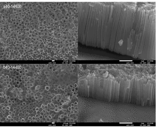
Figure 14. FE-SEM top and cross sectional view of anodized samples in ETG - 5% wt H2O
and 0,2% wt NH4F solution.
As observed in Figure 14, at lower anodizing time, both for the thin and the thicker foils, the top surface presents a porous layer rather than the more obvious nanotube morphology as that exhibited at longer times. In this later case, according to the cross section, the nanotube walls appear to be thicker at the bottom than on the top.
Comparing the current density curves of sample a40-14400 (5% wt H2O) and b40-14400
(7,5% wt H2O) (Fig. 15), they have similar shape but the final stationary density current value is
a bit lower in the 7,5% wt H2O, as expected [7].
Figure 15. Time evolution of same anodizing time and applied potential for 5% wt and 7,5% wt H2O. 0 5 10 15 20 0 2500 5000 7500 100001250015000 Cu rr ent d ens it y (m A/cm 2) Time (s) a40-14400 b40-14400 bP40-1800 b40-1800 b40-14400
Looking at FE-SEM images (Fig. 16), it is possible to see the differences in tube diameter and length; those with lower water content lead to a reduced diameter.
Figure 16. FE-SEM top and cross sectional view of samples a40-14400 and b40-14400.
Identification H2O % wt diameter [nm] Tube inner Tube length [m]
11.2 * 2,5 46 ± 7 5 aprox
a40-14400 5 79 ± 4 3,8 aprox
b40-14400 7,5 95 ± 4 1,6 aprox
Table 8. Average nanotube diameter and length in different water contents for anodizations at 40 V and 14400 s.
*Results extracted from Ivan Pacheco's work [19].
a40-14400
As shown in Table 8, the nanotube inner diameter increases by adding more water to the solution, and the nanotube length decreases. Adding more water increases the H+ ions in
solution, so it is believed that this factor accelerates the chemical dissolution of the oxide and hence causes shorter nanotubes length. Although the surface is cleaner and the nanotubes are more visible and opened, it breaks the nanotube top and makes an irregular surface. In very low water content, the donation of oxygen to form oxide is more difficult. For that reason, the maximum nanotube growth rate is achieved in medium amount of water. Moreover, the nanotube inner diameter increases; it is also linked to the acceleration of the chemical dissolution oxide rate [7, 18].
6.3.
T
WO-
STEP ANODIZATIONIn almost all the anodized samples, an irregular top oxide layer covers partially or totally the TiO2 nanotubes. At short anodizing times, this oxide layer covers almost the entire surface (Fig.
17).
Figure 17. FE-SEM cross sectional view of samples 1a70-1800 and b40-1800.
To obtain a smooth top surface free of oxide layer several procedures have been tested. One procedure is to perform a long anodization time in order to attack the oxide layer. The results obtained are better than the previous ones but there still exists part the oxide layer on the top and some remains of attacked nanotubes (Fig. 18).
Figure 18. FE-SEM top and cross sectional view of samples a30-14400 and b40-14400.
Looking at the cross sectional FE-SEM images of all the samples, a textured surface is observed where previously were oxide nanotubes. The growth of the tubular titanium oxide is the responsible of this structure.
Because of that, another procedure to obtain a smooth free oxide surface has been tested: a two-step anodization. The first step consists in anodize the sample and then remove the obtained structure with sonication in ethanol. The second step is to re-anodize the sample with the wished potential and time. First, it was tested the initial electrolyte solution of ETG with 5% wt H2O and 0,2% wt NH4F (Table 9).
a30-14400
Identification Time [s] Potential [V] as60-1800 1800 60 as70-1800 1800 70 as70-2700 2700 70 as70-3600 3600 70 as80-3600 3600 80 as80-5400 5400 80
Table 9. Experiments carried out at elevated potentials in ETG - 5% wt H2O and 0,2% wt
NH4F electrolyte.
At high potentials (Vanod>65V), oxide membranes show a bad adherence and partially or
totally fall. This is traduced in altered current density curves (Fig. 19) and a non-uniform anodization (Fig. 20).
Figure 19. Time evolution of current density at 70V.
Figure 20. Sample images of non-uniform oxidation at 70V. 0 10 20 30 40 50 0 1000 2000 3000 4000 Cu rr ent d ens it y (m A/cm 2) Time (s) as70-2700 as70-3600 as70-1800
Those experiments were considered a failure due to the irregular anodization, so it was decided to return to the initial conditions electrolyte, ETG - 2,5% wt H2O and 0,2% wt NH4F.
Experiments in Table 10 were performed.
Identification First anodization Second anodization diameter [nm] Average hole
Time [s] Potential [V] Time [s] Potential [V]
c70-3600* 3600 70 - - - c70-3600bis* 3600 70 - - - c70-7200* 7200 70 - - - c80-1800* 1800 80 - - - c80-3600 3600 80 - - - c80-3600re40-1800 - - 1800 40 - c80-3600bis 3600 80 - - - c80-3600bisre40-3600 - - 3600 40 60 ± 2 c80-3600-3* 3600 80 - - -
Table 10. Experiments carried out in ETG - 2,5% wt H2O and 0,2% wt NH4F electrolyte.
*The oxide layer couldn't be completely removed or the anodization was irregular.
Once the first anodization is done, it is attempted to remove the nanotube layer through sonication in ethanol. A problem occurred during the process, the oxide layer had an unexpected resistance and didn't fall. It has been necessary to bend the sample mechanically to make sure all the oxide came down. At this point, the second anodization was carried out. Figure 21 shows the final appearance of one sample.
Figure 22. FE-SEM top view images of sample c80-3600re40-3600.
Figure 22 shows the FE-SEM top view images. A highly ordered smooth porous hexagonal shape is observed, very different compared to the previous anodizations. In cross sectional view images (Fig. 23) also is noticed the smooth clean surface.
Figure 23. FE-SEM cross sectional view images of sample c80-3600re40-3600
The objective of obtaining a clean surface without the amorphous top oxide layer has been achieved, but a new drawback has appeared: the failure at removing the first nanotube layer formed. For that reason, it has been decided to prepare a new electrolyte solution. In an interesting study about two-step anodization in titanium dental implants [11], an ETG solution with 0,5% wt of fluorides was used with good results. Because of that, it was decided to increase the fluoride concentration on the present solution from 0,2% wt to 0,5% wt to test it.
Experiments in Table 11 were performed with that solution.
Identification First anodization Second anodization Average hole diameter [nm]
Time [s] Potential [V] Time [s] Potential [V]
d60-3600 3600 60 - - - d60-1800 1800 60 - - - d60-900 900 60 - - - d60-900bis 900 60 - - - d60-900-3 900 60 - - - d60-900-4 900 60 - - - d60-900bisre20-3600 - - 3600 20 32 ± 2 d60-900-3re30-1800 - - 1800 30 - d60-900re40-900 - - 900 40 45 ± 2 d50-1800 1800 50 - - - d50-1800bis 1800 50 - - - d50-1800-3 1800 50 - - - d50-1800-4 1800 50 - - - d50-1800-5 1800 50 - - - d50-1800-4re20-7200 - - 7200 20 35 ± 2 d50-1800-3re25-2700 - - 2700 25 47 ± 1 d50-1800re30-1800 - - 1800 30 50 ± 5 d50-1800bisre40-1800 - - 1800 40 63 ± 5
Table 11. Experiments carried out in ETG - 2,5% wt H2O and 0,5% wt NH4F electrolyte.
First experiments were performed to test the best potential and anodization time. Due to the increase of fluoride concentration it is believed to be a more aggressive solution, so potentials of 50V and 60V and short anodizing times were tested.
The first experiment was performed at 60V for 3600s (Fig. 24), and the result was that the sample became etched. The same problem occurred at 60V for 1800s.
Figure 24. Image of sample d60-3600.
However, at 50V for 1800s a uniform anodization was obtained and the sample was not etched. It also was decided to try at 60V one more time at 900s, and the result was a uniform anodization with a worse oxide layer adherence than at 50V for 1800s, so it has been decided to use those two conditions (60V-900s and 50V-1800s) to perform the rest of experiments. The current density curves (Fig. 25) have similar shape but different stationary value due to the different potential applied.
Figure 25. Current density curves of the two chosen conditions (50V-1800s and 60V-900s).
Once the first anodization is completed, samples are submerged into a baker with H2O2. It is
observed that in 3 sonications of 5 min each, the oxide layer is fully removed (Fig. 26).
Figure 26. d60-900-4 and d50-1800-5 images of half-oxidized half-sonicated samples. 0 10 20 30 40 50 0 500 1000 1500 2000 Cu rr ent d ens it y (m A/cm 2) Time (s) d60-900 d50-1800
Using FE-SEM (Fig. 27) characterization, the hexagonal shape textured substrate surface can be distinguished.
Figure 27. FE-SEM top view of textured substrate of samples d50-1800-5 and d60-900-4.
Afterwards, the second anodization procedure takes place and a uniform oxide layer is obtained. Figure 28 shows an example of a uniform two-step anodization.
Figure 28. Samples d50-1800re30-1800 and d60-900re40-900.
d50-1800-5
6.3.1. Anodizations at 50 V and 1800 s
Experiments in Table 12 (extracted from Table 11) were performed with a first anodization at 50V and 1800s.
Identification Time [s] Potential [V] Porous diameter [nm]
d50-1800-4re20-7200 7200 20 35 ± 2
d50-1800-3re25-2700 2700 25 47 ± 1
d50-1800re30-1800 1800 30 50 ± 5
d50-1800bisre40-1800 1800 40 63 ± 5
Table 12. Two-step anodizations with first anodization at 50V and 1800s.
Figure 29 shows the FE-SEM images of samples of Table 12 to compare the results.
d50-1800-4re20-7200
Figure 29. FE-SEM top view and cross sectional images of two-step anodized samples at different potential applied coming form a first anodization at 50V for 1800s.
Comparing the images of Figure 29, no important differences are appreciated. A clean smooth surface with the hexagonal structure of the first anodization is observed on the top, and within that structure several tubes can be distinguished (1-5). The nanotube porous diameter increases proportionally with potential applied, so at lower potentials (20-25V) 3-5 tubes per cell are found and at higher potentials (30-40V) 1-3 tubes per cell.
d50-1800re30-1800
Figure 30. Current density curves of samples in table 10
The current density curves (Fig. 30) have the same shape and the same progress is observed over time. Increasing the potential traduces in higher current density initial and stationary values.
6.3.2. Anodizations at 60 V and 900 s
Experiments in Table 13 (extracted from Table 11) were performed with a first anodization at 60V and 900s.
Identification Time [s] Potential [V] Porous diameter [nm]
d60-900bisre20-3600 3600 20 32 ± 2
d60-900-3re30-1800* 1800 30 -
d60-900re40-900 900 40 45 ± 2
Table 13. Two-step anodizations with first anodization at 60V and 900s. *Sample d60-900-3re30-1800 was not characterized by FE-SEM, so no images or tube diameter data are available.
Figure 31 shows the FE-SEM images of samples of Table 13 to compare the results. 0 5 10 15 20 25 30 35 0 5000 10000 Cu rr en t d en si ty (m A/cm 2) Time (s) d50-1800-4re20-7200 d50-1800-3re25-2700 d50-1800re30-1800 d50-1800bisre40-1800
Figure 31. FE-SEM top view and cross sectional images of two-step anodized samples at different potential applied coming form a first anodization at 60V for 900s.
Very similar results to the 50V-1800s anodizations have been obtained; there is a clean free-oxide surface where the hexagonal structure of the first anodization is visible, and underneath are found the nanotubes of the second anodization.
d60-900bisre20-3600
Figure 32. Current density curves of samples in table 11
Current density curves (Fig. 32) do not have any differences from the 50 V and 1800 s ones. In conclusion, very good results have been obtained in this stage. A clean free oxide surface has been achieved, and smooth well-defined nanotubes with a precise control of the cell geometry have been produced.
6.4.
D
IFFERENT ROUGHNESS SUBSTRATESThe third stage of the experiment is to obtain TiO2 nanotubes onto different roughness
substrates pre-treated with thermal spray techniques (Cold-gas-spray). Two types of roughness were studied, named CGS1 and CGS2.
6.4.1. Roughness characterization
In Table 14 the parameters of the different roughness samples are collected.
Nomenclature Waviness 3D Microroughness 3D Microroughness 2D
Sa Sz Sa Sz Ra Rz
CGS1 23 ± 5 107 ± 20 27 ± 2 362 ± 19 14 ± 3 59 ± 7
CGS2 21 ± 6 74 ± 5 15 ± 1 193 ± 18 13 ± 2 67 ± 14
Table 14. Information about roughness parameters of the two samples used 0 5 10 15 20 25 30 35 0 2000 4000 Cu rr ent d ens it y (m A/cm 2) Time (s) d60-900bisre20-3600 d60-900-3re30-1800 d60-900re40-900
In order to illustrate such results, Figure 33 and 34 show the 2D and 3D images of waviness and microroughness patterns of CGS1.
Figure 33. 2D images of waviness (left) and roughness (right).
Figure 34. 3D images of waviness (left) and roughness (right).
For more information check Appendix 1.
6.4.2. Nanotubes synthesis
Due to the good results obtained in the two-step anodization process, it is decided to directly perform a two-step anodization on the cold-gas-sprayed (CGS) titanium. Between the two first anodizations tested, the 60V-900s showed lower oxide layer adherence in comparison to the 50V-1800s, so considering the fact that with the increase of roughness it will be harder to remove the oxide layer, 60V-900s conditions have been used. Experiments in Table 15 have been performed.
Identification
First anodization Second anodization Average hole
diameter [nm] Roughness
Time
[s] Potential [V] Time [s] Potential [V] PR103-205_60-900 900 60 - - - CGS1 P1_60-900 900 60 - - - - PR103-222_60-900 900 60 - - 76 ± 5 CGS2 PR103-220_60-900 900 60 - - - CGS1 PR103-205_60-900re30-1800 - - 1800 30 39 ± 4 CGS1 P1_60-900re30-1800 - - 1800 30 73 ± 5 - PR103-222_60-900re30-1800 - - 1800 30 76 ± 6 CGS2 PR103-220_60-900re30-1800 - - 1800 30 - CGS1
Table 15. Experiments carried out with cold-gas-sprayed samples with ETG based electrolyte with 2,5% wt H2O and 0,5% wt NH4F.
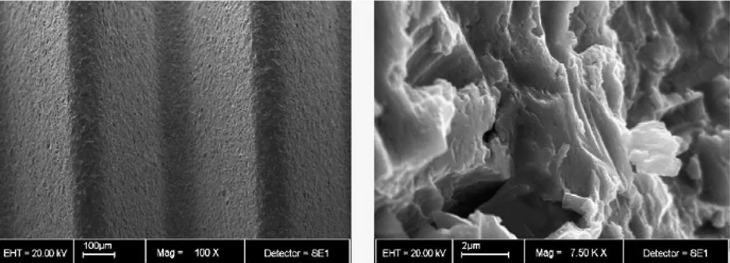
To illustrate the main differences, a 3-layer anodization has been performed. That means that the same sample is divided into 3 zones: non-anodized, first anodization and two-step anodization. Doing this, during the characterization with FE-SEM the 3 zones can be observed and compared. First anodization zone has also been under sonication with H2O2 to see if oxide
layer is properly removed. Figure 35 relates to sample PR103-205_60-900re30-1800 showing the 3-layer anodization.
Figure 35. 3-layer anodization sample: (1) non-anodized, (2) first anodization and (3) two-step anodization.
Figure 36. FE-SEM images of non-anodized, first anodization and two-step anodization (from left to right) zones of sample PR103-205_60-900re30-1800.
Figure 36 shows the difference between de 3-layer anodization. Non-anodized zone shows a micro-roughness surface without signs of nanostructures. This zone is very similar in all the characterized samples, therefore they are not worth to make a comparison and do not provide essential information.
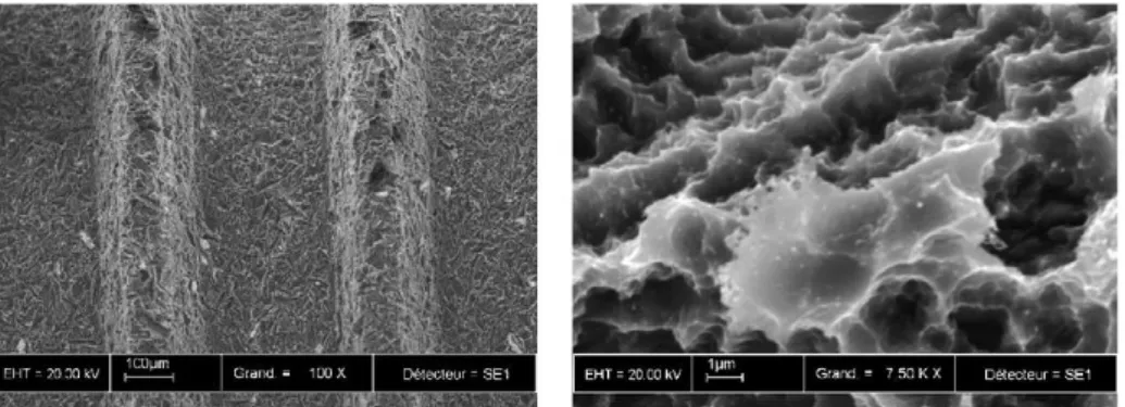
If a closer look is taken in the showed image (Fig. 37), in first anodization zone (second image) a nanoporous-nanotubular structure is noticed, where there should be only textured surface. Between the oxide blocks the marked surface can be seen, a fact that confirms that the first anodization oxide nanotube layer has not been removed properly. In Figure 38 the two-step anodization is shown. More defined nanotubes can be observed along the micro-roughness surface, but not with a smooth and clean top view surface like the obtained with the two-step anodization of flat samples.
Figure 37. FE-SEM images of first anodization zone of sample PR103-205_60-900re30-1800.
Figure 38. FE-SEM images of two-step anodization zone of sample PR103-205_60-900re30-1800.
In the anodization of samples PR103-222_60-900re30-1800 and PR103-220_60-900re30-1800 a problem occurred. FE-SEM images (Fig. 39) of the two-step anodization zone show a non-tubular compact oxide layer. Using the same anodizing conditions than the previous experiment, very different results are obtained. Responsible for this problem might be the electrolyte ageing effect. After several experiments, the electrolyte does not have the same initial conditions (fluoride and water concentration...) because of the reactions occurred between H2O and Ti4+ or TiO2 and F-, so after more than 20 anodizations it is possible that almost all the
fluoride has reacted and formed [TiF6]2- species.
Figure 39. FE-SEM images of the two-step anodization zone of samples PR103-222_60-900re30-1800 (1) and PR103-220_60-PR103-222_60-900re30-1800 (2).
According to the last results, it is decided to prepare a new solution with the same conditions (ETG based electrolyte with 2,5% wt H2O and 0,5% wt NH4F). Experiments in Table
16 were carried out.
Identification Time [s] Potential [V] Average hole diameter [nm] Roughness
PR103-224_60-1200 1200 60 62 ± 7 CGS2
PR103-206_60-900 900 60 - CGS1
PR103-206_60-1800 1800 60 58 ± 6 CGS1
PR103-224reu70-900 900 70 - CGS2
PR103-220reu80-900 900 80 - CGS1
Table 16. Experiments with new ETG - 2,5% wt H2O and 0,5% wt NH4F electrolyte.
Sample PR103-224_60-1200 was performed at same potential applied but with longer anodization time with later sonication in H2O2 to see if oxide layer is removed. Images in Figure
40 prove that the nanotube oxide layer still exists and seems to have been attacked.
Figure 40. FE-SEM images of sample PR103-224_60-1200.
At this point, it is decided to focus next experiments in two directions: increase the potential applied (with the following sonication in H2O2) to make the oxide layer fall easily, and to perform
Results in the first direction are unsatisfactory; images (Fig. 41) of anodizations at 70 and 80 V for 900 s show no differences, and the nanotube oxide layer is still present.
Figure 41. FE-SEM images of samples PR103-224reu70-900 and PR103-220reu80-900 where the nanotubes oxide layers are observed.
In the second direction, a single 60 V anodization at two different times (900 and 1800 s) has been carried out. The aim is to see which results are obtained with just a one-step anodization process (Fig. 42). In one hand, at 900 s anodization time a nanotubular structure can be seen, but widely covered by a compact oxide layer, similar to the first experiments of this project. In the other hand, at 1800 s anodization time, well-defined tubes are appreciated and a cleaner surface, but still no free of the compact oxide layer.
70 V 80 V
PR103-206_60-900
Figure 42. FE-SEM images of one-step anodizations of 60 V at different times.
In conclusion, using the standard procedure utilized with smooth titanium samples anodization, different results have been obtained. The first anodization oxide layer has not been removed satisfactorily; therefore it has not been possible to perform a second anodization. Further research is necessary to modify conditions in order to optimize the procedure and obtain better results.
6.4.3. Coloured titanium oxide
The results obtained in the nanotube synthesis are disturbing. The nanotube formation is irregular all over de surface, so it is decided to test if the cold-gas-sprayed (CGS) Titanium has the same behaviour as smooth Titanium samples in an experiment: coloured Titanium.
Coloured Titanium oxide layers can be obtained through anodization in a water-based electrolyte containing fluorides (2,5% wt NH4F) [19]. There is a correlation between the potential
applied and the colour observed (Fig. 43a). So, experiments in Table 17 have been carried out.
Identification Time [s] Potential [V] Roughness
PR103-223_60-10 10 60 CGS2
PR103-223_70-10 10 70 CGS2
PR103-223_80-10 10 80 CGS2
Table 17. Experiments carried out with water based electrolyte with 2,5% wt NH4F.
PR103-206_60-1800
Looking at Figure 43b, a phenomenon is observed. The 60V anodization zone of the cold-gas-sprayed sample should be orange coloured. However, it seems to appear a colour "gradation". In the middle, it looks like if the potential is lower than the applied one (yellow=50V) and as it moves to the edges the colour changes following a potential increase (orange=60V purple=70V blue=80V). In the 70V anodization it can be observed the same behaviour occurred in the previous zone more clearly. In the 80V zone is also observed the potential augmentation, but in comparison with the 60-70V zones, the middle is not suffering a lower potential anodization.
Figure 43. Images of coloured titanium oxide layers of Ivan Pacheco's work [19] (a)and cold-gas-sprayed anodization sample (b) with water based electrolyte with 2,5% wt NH4F.
(a)
6.4.4. Contact angles
According to Bauer et al. [20], TiO2 nanotube layers show a super-hydrophilic behaviour,
and that feature affects cell adhesion, spreading and growth.
As first studies, contact angle between liquid and a solid surface has been measured to compare the wettability of different surfaces (smooth or rough) with and without TiO2 nanotubes
presence. Table 18 collects the results of the performed measurements.
Identification Left angle left Right angle right
smooth sample 93,508 3,744578247 94,164 6,621096957
d60-900-4 16,742 - 18,388 -
PR103-221 54,3255 8,043508231 50,2635 4,448460736
PR103-206_60-1800 - - - -
Table 18. Angles values and standard deviations of different roughness samples with and without nanotubes presence.
Figure 44. Contact angle images of different samples studied.
Smooth Ti sample d60-900-4
Smooth Titanium sample showed a hydrophobic behaviour, the contact angle was about 90 degrees, but the anodized flat titanium sample, on the contrary, increased wettability to a level that reduced the contact angle to less than 20 degrees.
In the rough samples, it is believed that a higher roughness reduces the contact angle (becomes more hydrophilic). Comparing the non-anodized samples (smooth Titanium sample and PR103-221), the rougher sample shows a contact angle of approximately 50 degrees, that more or less is half of the smooth sample result.
With the anodized rough sample PR103-206_60-1800, it was not possible to measure the contact angle. When the water drop touched the surface, immediately got absorbed. This phenomenon suggests that the rough surface with the addition of nanotubes presence increased wettability to the maximum level. The hydrophilic nature of the TiO2 nanotubes is
attributed to the capillary effect of the nanotubes. Due to the capillary effect, the water droplet is sucked quickly into the pores of the tubes, which causes the contact angle to be reduced dramatically [18].
Results obtained correspond to expectations; the nanotubes presence strongly affects the surface wettability and provides a hydrophilic behaviour in both cases. Improved wettability, i.e., low contact angle, leads to high surface energy, which is one of the key factors in better cell adhesion process.
7.
C
ONCLUSIONS
After the optimization of the electrolyte composition and electrochemical parameters, it has been possible to obtain TiO2 nanotubes with a smooth surface on titanium smooth foils with
control of the inner diameter. Mainly, this can be summarised as follows:
- Increasing the electrolyte water concentration (2,5 5 7,5% wt) leads to an increase of nanotube inner diameter and a decrease of the nanotube length. - At short anodizing times a compact oxide layer on the top covering the tubes is
observed, and at long anodizing times a cleaner surface (but not completely clean) with opened tubes is found.
- In two-step anodizations with ETG 2,5% wt H2O and 0,2% wt NH4F good results
are obtained, but the first anodization oxide layer has not been possible to remove.
- Increasing the fluoride concentration to 0,5% wt, best results are obtained: clean smooth surfaces with controlled tubes diameters from 30 nm to 60 nm have been achieved performing two-step anodizations.
Although similar diameters to those reported for good bioactive response have been obtained (30 nm), a biocompatibility and bioactivity assay should be done to extract final conclusions. Still some controversy exists on this topic.
In the study of surface modified rough samples, quite nice results were observed but still further optimization is needed. With just a one-step anodization some nanotubes were not completely opened keeping part of the compact original oxide layer. It has not been possible to reproduce the results obtained in the smooth samples; the first anodization oxide layer could not be completely removed so it was not possible to perform a correct two-step anodization.
Coloured rough titanium experiment showed that the applied voltage is not uniform all over the sample; so further study is necessary to identify the problems and achieve a regular oxide formation in the entire anodized surface.
8.
R
EFERENCES AND NOTES
1. Macak, J.M., Tsuchiya, H., Ghicov, A., Yasuda, K., Hahn, R., Bauer, S., Schmuki, P. (2007). TiO2
nanotubes: Self-organized electrochemical formation, properties and applications. Solid state and
materials science, 11 (3-18), 1-16.
2. Roy, P., Berger, S., Schmuki, P. (2011). TiO2 Nanotubes: Synthesis and Applications. Angew. Chem.
Int. Ed., 50, 2905-2927.
3. Kulkarni, M., Mazare, A., Schmuki, P., Iglič, A. (2014). Biomaterial surface modification of titanium and titanium alloys for medical applications. Nanomedicine, 5, 112-130.
4. Mu-Hyon, K., Kyeongsoon, P., Kyung-Hee, C., Soo-Hong, K., Se Eun, K., Chang-Mo, J., Jung-Bo, H. (2015). Cell Adhesion and in Vivo Osseointegration of Sandblasted/Acid Etched/Anodized Dental Implants. Int. J. Mol. Sci., 16, 10324-10336.
5. Gu´ehennec, L., Soueidan, A., Layrolle, P., Amouriq, Y. (2007). Surface treatments of titanium dental implants for rapid osseointegration. Dental materials, 23, 844–854.
6. Mor, G., Varghese, O., Paulose, M., Shankar, K., Grimes, C. (2006). A review on highly ordered, vertically oriented TiO2 nanotube arrays: Fabrication, material properties, and solar energy
applications. Solar Energy Materials & Solar Cells, 90, 2011–2075.
7. Reza, M., Naghizadeh, M., Abdizadeh, H. (2013). Effect of Fluoride Concentration and Water Content on Morphology of Titania Nanotubes in Ethylene Glycol Solution. Advanced materials research, 1-6. 8. Thompson, T., Yates, J. (2006). Surface Science Studies of the Photoactivation of TiO2-New
Photochemical Processes. Chem. Rev., 106, 4428-4453.
9. Ghicov, A., Schmuki, P. (2009). Self-ordering electrochemistry: a review on growth and functionality of TiO2 nanotubes and other self-aligned MOx structures. Chem. Commun., 2791–2808.
10. Park, J., Bauer, S., Von der Mark, K., Schmuki, P. (2007). Nanosize and Vitality: TiO2 Nanotube
Diameter Directs Cell Fate. Nano Lett., 7 (6), 1686-1691.
11. Jang, I., Shim, S., Choi, D., Cha, B., Lee, J., Choe, B., Choi, B. (2015). Effect of TiO2 nanotubes
arrays on osseointegration of orthodontic miniscrew. Biomed Microdevices, 17 (76), 1-7. 12. Mor, G., Shankar, K., Paulose, M., Varghese, O., Grimes, C. (2005). Use of Highly-Ordered TiO2
Nanotube Arrays in Dye-Sensitized Solar Cells. Nano Lett., 6 (2), 215-218.
13. Shankar, K., Mor, G., Prakasam, H., Yoriya, S., Paulose, M., Varghese, O., Grimes, C. (2007). Highly-ordered TiO2 nanotube arrays up to 220 μm in length: use in water photoelectrolysis and dye-sensitized solar cells. Nanotechnology, 18, 1-12.
14. Mor, G., Carvalho, M., Varghese, O., Pishko, M., Grimes, C. (2003). A room-temperature TiO2
-nanotube hydrogen sensor able to self-clean photoactively from environmental contamination. J.
Mater. Res., 19 (2), 628-634.
15. Xie, Y., Ao, H., Xin, S., Zheng, X., Ding, C. (2014). Enhanced cellular responses to titanium coating with hierarchical hybrid structure. Materials Science and Engineering C, 38, 272-277.
16. Yavari, S., Chai, Y., Böttger, A., Wauthle, R., Schrooteng, J., Weinans, H., Zadpoor, A. (2015). Effects of anodizing parameters and heat treatment on nanotopographical features, bioactivity, and cell culture response of additively manufactured porous titanium. Materials Science and Engineering C, 51, 132-138.
17. Song, Y., Schmidt-Stein, F., Bauer, S., Schmuki, P. (2009). Amphiphilic TiO2 Nanotube Arrays: An
18. Indira, K., Kamachi Mudali, U., Nishimura, T., Rajendran, N. (2015). A Review on TiO2 Nanotubes:
Influence of Anodization Parameters, Formation Mechanism, Properties, Corrosion Behavior, and Biomedical Applications. J Bio Tribo Corros, 1 (28), 1-22.
19. Pacheco, I. (2015). Study of the Titanium anodization process to produce biocompatible surfaces.
Universitat de Barcelona, 1-47.
20. Bauer, S., Park, J., Von der Mark, K., Schmuki, P. (2008). Improved attachment of mesenchymal stem cells on super-hydrophobic TiO2 nanotubes. Acta Biomaterialia, 4, 1576–1582.
A
PPENDIX
1:
R
OUGHNESS CHARACTERIZATION
BASIS
Confocal microscopy is an optical imaging technique for increasing optical resolution and contrast of a micrograph by means of adding a spatial pinhole placed at the confocal plane of the lens to eliminate out-of-focus light. It enables the reconstruction of three-dimensional structures from the obtained images.
The most important feature of a confocal microscope is the capability of isolating and collecting a plane of focus from within a sample, thus eliminating the out of focus "haze" normally seen with a fluorescent sample. A confocal imaging system achieves out-of-focus rejection by two strategies: a) by illuminating a single point of the specimen at any one time with a focussed beam, so that illumination intensity drops off rapidly above and below the plane of focus and b) by the use of blocking a pinhole aperture in a conjugate focal plane to the specimen so that light emitted away from the point in the specimen being illuminated is blocked from reaching the detector.
This microscopical technique has been used in order to evaluate the roughness of the surface modified samples before anodizing.
Roughness is a measure of surface texture that has an important role in determining the interaction between the surface and its functional environment. One of the most common methods to evaluate the roughness is by using a profilometer (dragging a tip over the surface), but this does not allow separating the contribution according to different wavelengths. Surface texture of any material can be actually separated in various components depending on the wavelength of the surface topography. The wavelength is the inverse of the frequency, so the higher the frequency the lower the wavelength. If the different components of surface texture depending on the wavelength are separated, we obtain microroughness, roughness, waviness and form, as it can be observed in Figure 33. Each component has an effect on the interaction of the surface with the medium. In the case of a biomedical device, for example, the micro or nanotopography will be determining for the cellular accommodation. The components can be
separated applying a filter with a wavelength c (fc=1/c). Higher frequencies than fc will be roughness and lower frequencies will be waviness.
Figure 45. Scheme of texture components according to the topography wavelength.
Roughness parameters meaning:
Average roughness (Ra): Expresses the arithmetic average of the absolute Z (x) values in length sampling.
Maximum height of the roughness profile (Rz): Expresses the sum of he maximum height peak (Rp) and the maximum value of valley depth (Rv) in length sampling.
Average roughness (Sa): Expanded 3D parameter from Ra (2D). Expresses the average of the absolute values of Z (x,y) in the measured area.
Maximum surface height (Sz): Expanded 3D parameter from Rz (2D). Expresses the sum of the maximum value of peak height Zp and the maximum valley depth value Zy within the measured surface.
A
PPENDIX
2:
C
ONTACT ANGLE INFORMATION
The contact angle is the angle, conventionally measured through the liquid, where a liquid/vapour interface meets a solid surface. It quantifies the wettability of a solid surface. A hydrophobic behaviour is traduced in a high contact angle with bad wettability and hydrophilic behaviour is traduced in a small contact angle with good wettability.