1
SCUOLA NORMALE SUPERIORE
New Fluorescent Tools For The Development of Advanced
Vapochromic Films Based on Themoplastic Polymers
Supervisor: Prof. Andrea Pucci Candidate: Muzaffer Ahmad Co-supervisor: Dr. Giuseppe Brancato
3
Acknowledgements
The work was carried out at the Department of Chemistry and Industrial chemistry at the University of Pisa. I would like to begin with my sincere thanks to my supervisor Prof. Andrea Pucci for granting me an opportunity to work in his laboratory. He has been always highly supportive and encouraging throughout my research work. I would also like to thank my co-supervisor Dr. Giuseppe Brancato for his kindness and support.
I must thank all the people here in the department of chemistry particularly who have been around me during this entire period. I would like to thank to Pierpaolo, who is not working here now, for his support particularly at the initial stages in the department. I would always remember his support to learn the new techniques during my research work. I would also like to mention the other people who have been equally supportive and my friends including Giuseppe, Francesco, Serani, Mirko and Matteo. I never thought that I am far away from my home in their company. I would consider myself lucky to have such wonderful people around me. I would also like to pay my thanks to all other master students who have been with me throughout my stay in the department particularly Francesca, George, Guada, Irene, Matteo and Jonathan. I am sorry if I missed to mention the name of some people.
I wish to thank the people from other laboratories particularly Dario, Sabrina, Guazelli and Sara for allowing me to perform the DSC measurements. I would also like to thank to Dr. Elisa Passaglia and Roberto from CNR for allowing me to make DSC analysis in their laboratory. I am also grateful to the people of NEST for performing some analysis of my research work, especially, my co-supervisor Dr. Giuseppe Brancato for computational calculations and Antonella Battisti for the confocal imaging.
I would also like to thank my friends from Scuola Normale Superiore who have also been a wonderful part of my stay here in Pisa, particularly for having the food together in the canteen. I am also thankful to all other people in the administrative service of the scoula for being always available.
I must thank my parents who allowed me to choose my carrier without any interference. I know it was not so easy for them to let me stay far away from them. They never let me feel that I was far away from them. I am also thankful to my two elder brothers for their support and encouragement.
4
Finally, I wish to thank the Scuola Normale Superiore for the grant of PhD scholarship and department of chemistry of the University of Pisa for giving me an opportunity to work in the department.
5
Abstract
The harmful effects of Volatile Organic Compounds (VOCs) demand simple sensitive, selective and cost effective sensors for their detection. Considering this fact, the sensing ability of the fluorescent molecules for the detection of VOCs is demonstrated in this work. In particular, here in we investigated the vapochromic behaviour of special fluorescent molecules known as fluorescent molecular rotors (FMRs), sensitive to both viscosity and polarity of the environment. The higher sensitivity of FMRs in determining the microviscosity changes inspired their application as sensors for VOCs. The sensor system was prepared by the dispersion of a very small amount (0.05-0.1 wt. %) of 4-(diphenylamino)phthalonitrile (DPAP) within poly(methyl methacrylate) (PMMA) and polycarbonate (PC). DPAP/PMMA films show a good and reversible vapochromism when exposed to the VOCs with high polarity index and favourable interaction with the polymer matrix such as tetrahydrofuran (THF), chloroform (CHCl3) and acetonitrile. Analogously, DPAP/PC
films exposed to polar and highly polymer-interacting solvents, that is, toluene, THF, and CHCl3 show a gradual decrease and red-shift of the emission. Contrary to
DPAP/PMMA films, an unexpected increase and further red-shift of fluorescence is observed at longer exposure times after the initial decrease as a consequence of an irreversible, solvent-induced crystallization process of PC. The vapochromism of DPAP-doped polymer films is rationalized on the basis of alterations of the rotor intramolecular motion and polarity effects stemming from the environment, which, in concert, influence the deactivation pathways of the DPAP intramolecular charge transfer state. The present results support the use of DPAP-enriched plastic films as a new chromogenic material suitable for the detection of VOCs.
We also investigated, in some detail, the effect of the polymer film thickness on the vapochromic response of a new FMR namely 4-(triphenylamino) phthalonitrile (TPAP) in PC films. The results were discussed in terms of both the spectral signal features and the kinetics of its response. PC films of variable thickness (from 20 to 80 μm) containing small amount of TPAP were exposed to the saturated atmosphere of different VOCs. Interestingly, the fluorescence behaviour of the TPAP/PC films shows a non-trival tuneable dependence of film thickness during the second solvent exposure stage. The latter effect is attributed to the variable extent of the crystallization process occurring in PC films based on their thickness. This
6
observation suggests an effective procedure to modulate the spectroscopic response in such functionalized polymeric materials through a precise control of the film thickness.
The vapochromic properties of a solvatochromic dye 3-[2-(4-nitrophenyl) ethenyl]-1-(2-ethylhexyl)-2-methylindole (NPEMI-E) characterized by intramolecular charge transfer (ICT) character, dispersed in polycarbonate (PC) films is also reported. NPEMI-E solvatochromism is investigated by means of experimental and computational methods. NPEMI-E/PC films show remarkable and reversible vapochromism when exposed to VOCs with high polarity index and favourable interaction with PC matrix such as CHCl3. Only
minor variations of the emission wavelength are actually recorded for all other classes of VOCs investigated. The hue parameter is also used for the effective extraction of spectral information from digital colour images without the need for wavelength discriminators. Overall, the present results support the use of NPEMI-E/PC films for the cost-effective detection of CHCl3 vapours.
Finally, we investigated the effect of polymer glass transition temperature (Tg) on the
vapochromic behaviour of highly viscosity sensitive FMR, 2-(methylbutyl)-2-cyano-3-julolidine acrylate (MBCJA). Mixing of poly(methyl methacrylate) (PMMA) and poly(butyl methacrylate) (PBMA) in different compositions with the fluorophore resulted in new compatible polymer blends with different Tg. The vapochromic response of the dye
containing pure PMMA and PBMA films indicated a better variation in the emission intensity contrary to blends. Based on the strong compatibility and single Tg of the blends, strong
intermolecular interactions are supposed to play a significant role in hampering the solvent interaction with blends. These interactions along with Tg must probably play the role in the
solvent interaction with blends and accordingly changed the fluorescence response of the fluorophore mixed in polymer matrices.
7 Table of contents
Acknowledgements ... 3
Abstract ... 5
1. Introduction ... 10
1.1. Volatile Organic Compounds ... 10
1.1.1. Sources of VOCs ... 12
1.1.2. Methods for the detection of VOCs ... 13
1.2. Fluorescence methods for VOCs detection... 16
1.2.1. Mechanism of Fluorescence ... 16
1.2.1.1. Fluorescence quenching ... 18
1.2.1.2. Phosphorescence ... 19
1.2.1.3. Non-Radiative pathways of deactivation ... 19
1.2.1.4. Types of fluorescent molecules ... 19
1.3. Fluorescent Molecular Rotors ... 20
1.3.1. FMRs based on julolidine ... 23
1.3.2. Applications of FMRs ... 24
1.3.3. Effect of polarity on FMRs ... 27
1.3.4. Fluorescent molecules as vapochromic sensors ... 28
1.3.5. FMRs as vapochromic sensors ... 31
1.4. Aggregation induced emission (AIE) in fluorophores ... 33
1.4.1. Application of AIEgens ... 35
1.4.2. AIEgens as VOCs sensors ... 36
1.5. Solvatochromic probes as sensors for the detection of VOCs ... 38
1.6. Polymers as supporting materials for fluorescent molecules ... 43
1.6.1. Preparation of dye/Polymer films ... 44
1.7. Vapour permeation in polymers... 46
1.7.1. Effect of diffusion ... 46
1.7.2. Effect of pressure ... 47
1.7.3. Effect of solubility parameter (δ) and Flory-Huggins interaction parameter (χ) ... 48
1.7.4. Effect of polymer free volume ... 49
1.7.5. Effect of molecular weight of polymers ... 50
1.7.6. Effect of the solvent ... 51
8
1.9. Structural and morphological changes in glassy polymer on exposure to VOCs ... 52
2. Fluorescent molecular rotors as vapochromic sensors ... 55
2.1. Introduction ... 55
2.2. Experiments ... 58
2.2.1. Materials and Methods ... 58
2.2.2. Preparation of polymer films ... 58
2.2.3. Apparatus and Methods ... 59
2.3. Results and Discussion ... 60
2.3.1. Spectroscopic characterization of DPAP/polymer films ... 61
2.3.2. Effect of VOC exposure on the optical emission of DPAP/PMMA films ... 63
2.3.3. Effects of VOC exposure on the optical emission of DPAP/PC films ... 67
2.4. Effect of polymer thickness on the vapochromic behaviour of TPAP/PC films ... 74
2.4.1. Effects of VOC exposure on the optical emission of TPAP/PC films ... 76
2.4.2. Differential Scanning Calorimetry (DSC) of TPAP/PC films... 81
2.5. Conclusions ... 84
3. Solvatochromic Probe for the Selective Detection of Volatile Organic Solvents (VOCs).. 86
3.1. Introduction ... 86
3.2. Experimental ... 87
3.2.1. Materials and Methods ... 87
3.3. Apparatus and Methods ... 88
3.4. Hue-based quantification of vapochromism ... 90
3.5. Quantum mechanical calculations ... 91
3.6. Results and Discussion ... 91
3.6.1. Spectroscopic characterization of NPEMI-E in solution ... 91
3.6.2. Intramolecular charge transfer (ICT) mechanism ... 95
3.6.3. Spectroscopic characterization of NPEMI-E/polymer films ... 97
3.6.4. Effect of VOC exposure on the emission spectra of NPEMI-E/Polymer films ... 98
3.6.5. Reproducibility and reversibility of the behaviour of NPEMI-E/PC films ... 103
3.6.6. HUE-based quantification of CHCl3 exposure ... 103
3.7. Conclusions ... 105
4. Effect of Glass Transition Temperature (Tg) on the Vapochromism of FMR in Polymer.106 4.1. Introduction ... 106
9
4.2.1. Materials and methods ... 107
4.2.2. Synthesis of 2-(methylbutyl)2-cyanoacetate (MBCA) ... 108
4.2.3. Synthesis of 9-formyljulolidine (FJUL) ... 110
4.2.4. Synthesis of 2-(methylbutyl)-2-cyano-3-julolidine acrylate (MBCJA) ... 110
4.2.5. Preparation of PMMA/PBMA blend with MBCJA films ... 113
4.2.6. Characterization ... 113
4.3. Results and discussions ... 114
4.3.1. Optical properties of MBCJA in solution ... 115
4.3.2. Spectroscopic characterization of polymer films ... 119
4.3.3. Glass transition temperature (Tg) of polymer films ... 121
4.3.4. Effect of VOCs exposure on MBCJA/polymer films ... 122
4.4. Conclusions ... 127
5. General Conclusions and Perspectives ... 128
6. Characterization techniques ... 132
6.1. Fluorescence spectroscopy ... 132
6.2. UV-Vis Spectroscopy ... 132
6.3. Fourier-Transform-Infrared Spectroscopy ... 132
6.4. Nuclear Magnetic Resonance ... 132
6.5. Differential Scanning Calorimetry ... 133
6.6. Film Thickness ... 133
6.7. Confocal Microscopy Imaging ... 133
6.8. Quantum mechanical calculations ... 134
6.9. Hue method ... 134
10
Chapter 1
1. Introduction
1.1. Volatile Organic Compounds
Volatile Organic Compounds (VOCs) are the organic chemicals that form vapours at normal temperature and pressure. According to the World Health Organization (WHO), VOCs are considered to be the organic compounds having boiling point in the range of 50–260 °C. On the basis of the degree of volatility and the boiling point, VOCs are classified into three types (Table 1). VOCs are also classified on the ozone forming potential, polarity and their effects on ecosystems.1,2
Table 1 Classification of VOCs on the strength of volatility and boiling point range.
Name Boiling point range (°C) Examples
Very Volatile Organic Compounds (VVOCs) <0-100 Propane, butane, methyl chloride Volatile Organic Compounds (VOCs) 50-100 to 240-260 Aldehydes, toluene, acetone,
alcohols
Semi-Volatile Organic Compounds (SVOCs) 240-260 to 380-400 pesticides including DDT, chlordane etc.
The uncontrolled release of chemicals containing VOCs into the environment can cause the generic health problems thereby effecting the population, particularly, in urban and industrial areas.3–6 The harmful effects of VOCs on human health mostly include acute and chronic respiratory effects, eye and throat infection etc.6–9 The effect on human health depends on the total concentration of the VOCs as well as the exposure time. It is reported that below 0.20 mg/m3 no effects are evident and above this level of exposure, the effects start to multiply. The toxic exposure range is believed to occur at concentration above 25 mg/m3.10 The effect of exposure time on the intensity of combined eye, nose and throat irritation was reported by Molhave et al.11 Accordingly, the irritation was recorded after the 75 min exposure to VOCs and reached the significant value after 2.75 h compared to the exposure to clean air.11 The other effects including headache, drowsiness etc. were also realized. The study also indicated
11
that both olfactory and trigeminal systems are activated by the exposure to VOCs and the perception of odour intensity decreases with exposure time.11
Solvents like benzene have proven to be to carcinogenic and account for about 40% of the risks for each category of indoor environment.12 Life time risk associated with exposure to benzene in smoking areas is much higher than non-smoking homes. Exposure to higher concentration of benzene could lead to the circulatory and immunological dysfunctions. VOCs including 1,1,-dichloroethane, methylene chloride, chloroform and trichloroethane used as solvents, detergents and insectsides are also associated with higher lifetime risks.12 Rumchev et al. investigated the association of VOCs and asthma and concluded that most of the VOCs appeared to contribute significantly to the risk of asthma.13 Benzene followed by ethyl benzene and toluene were considered to be significant risk factors for asthma. They also reported that for every 10 unit increase in benzene (μg/m3
), the probability of asthma increased to three times.
The potential effects of chlorinated VOCs (Cl-VOCs) including polychloromethanes, polychloromethanes and polychloroethylene on human health is one of the growing concern of VOCs.4 These compounds have high volatility and resistance to degradation thereby can enter our body easily through inhalation. The source for such Cl-VOCs include metal degreasing, dry cleaning, manufacture of pesticides, adhesives etc. Chloroform, one of the Cl-VOCs, is highly volatile and unreactive and slightly dissolves in water. Due to its broader applications, the total global annual production of chloroform in the late 1990 was about 520000 tonnes.14 Exposure to chloroform may cause severe health related problems including mutagenesis, cytotoxicity etc.15 The other Cl-VOCs including carbon tetrachloride, dichloromethane etc. are also reported to pose serious effects on health and needs to be monitored regularly.
VOCs also influence the atmosphere by forming ozone on reacting with OH radicals in presence of light in troposphere.2,16 1,3-butadiene and 1,3,5-trimethylbenzene are reported to have higher potential for ozone formation.2 Tropospheric ozone has harmful effects on both plants and human beings. Contrary, halogen containing VOCs react with ozone in stratosphere thereby enhancing the depletion of ozone, which in turn allows the harmful UV radiations to pass through it easily. The reaction of VOCs with natural constituents of air also leads to their partial degradation. The formation of secondary pollutants of higher toxicity can occur during the photo-degradation of VOCs in the atmosphere. The photo-degradation of
12
trichloroethylene to phosgene gas illustrates this effect very well.16 The life time of VOCs in the atmosphere depends on the oxidation by tropospheric hydroxyl radicals.17 Alkanes generally have life time of about 2-30 days while methane and ethane have 10 years and 120 days respectively.17 On the other hand alkenes have shortest life time among the organic compounds (0.4-4 days), almost similar to aromatic hydrocarbons.
1.1.1. Sources of VOCs
VOCs enter into the environment from different sources including industrial process, transportation, agriculture etc.8,18–21 For example, non-methane hydrocarbons enter into the environment by burning of fossil fuels, vegetation, transportation, geochemical changes etc. The oxidation of these compounds leads to the formation of ketones, aldehydes, alcohols, and phenols etc., which are considered harmful for human health. The anthropogenic contribution usually comes from the exploitation of fossil fuels. Methane is released from the coal production. Many gases usually hydrocarbons including methane, ethane, propane, butane etc. are released during crude oil production.22 Emission from vehicles contributes to the highest increase of VOCs in the form of non-methane hydrocarbons (NMHCs) in the public environment. In particular, the emission from the gasoline and diesel combustions results in the production of paraffins (C1-C5) and methane respectively. The other VOCs formed
involve olefins, aromatic hydrocarbons, aldehydes, ketones and other higher molecular weight paraffins.22
The presence of VOCs in indoor environment is also a growing concern since some studies indicate higher level of VOCs concentration in indoor environment than outdoor environment.23 The indoor VOCs mostly include aromatics, aldehydes and halocarbons. Many sources are involved for the release of indoor VOCs, however, the building materials are considered as main sources.23 The release of several VOCs including ethyl benzene, 1,1,1, trichloroethane, xylenes etc. from the new buildings decrease over the time indicating that sources are related to materials or finishing. 24
Photocopy centres are also considered potential sources of many VOCs including benzene, toluene, ethyl benzene, xylene and styrenes (BTEXS).25 The toner powder that contains the organic components is believed to the source of VOCS in photocopy centres.26 In general, there is wide variation of VOCs identified in different photocopy centres however, toluene and 1,2,4-trimethylbenzene were found in all the centres investigated.26
13
Natural resources of VOCs include marine and terrestrial environments. Plants release VOCs in the form of isoprenes and trepenes, which are actually reduced forms of the carbon, during photosynthesis and are among the most abundant sources of biogenic VOCs.22 Biogenic emissions also contain other kinds of VOCs including alcohols, esters, aldehydes, ketones, alkenes and alkenes. Some studies reported that alkanes and aromatics contribute significantly to the VOC emission from plants, however, most of the findings contradict this report. Biogenic VOCs are also involved in the production of organic acids, organic nitrates and organic aerosols.27 The harvesting and grazing practices are also responsible for the emission of NMVOC to some extent. Drying of vegetation is also reported to play a significant role in the NMVOC emission. Consequently, the emission of VOCs from plants is becoming an interesting research area. The measurement of biogenic VOCs in Europe have been carried out by Biogenic emissions in the Mediterranean area (BEMA) and Biogenic VOC emissions and photochemistry in boreal regions of Europe (BIPHOREP).27 Some soil microorganisms are also reported to release some VOCs into the atmosphere.28 A relatively small amount of organic compounds in the form of alkanes and alkenes are also emitted from the ocean. The contribution of volcanic eruptions, combustion of organic matter and biomass and forest fires has to be taken into account as well.2,28,29
1.1.2. Methods for the detection of VOCs
The growing concern of VOC emission has forced the many countries around the globe to limit and monitor the use of VOCs. In Europe, VOC Solvent Emissions Directive (council directive 1999/13/EC of 11 March 1999) was issued by the council of European Union for the reduction of industrial emissions of VOCs in Europe. In Unites States the VOCs are regulated by the United States Environmental Protection Agency (USEPA). In China the Ministry of Environmental Protection of China has classified VOCs as major pollutant.30 According to Wang et al. China produced more than 6.5 million tons of VOCs in 2010 and the level is going to rise further in future due the industrial growth.31 The Atmospheric Pollution Prevention Law in China manages and monitors VOCs from the pollution sources. In India the Central Pollution Control Board has regulated Benzene and Benzo(a)pyrene by including them in National Ambient Air Quality Standard to control their release into the environment.32 The Global Emissions Inventories Activity (GEIA), a part of the International Global Atmospheric project (IGAC) has also recognized VOC as a part of their programme.19
14
All these issues with VOCs demand suitable sensors for their detection with higher sensitivity and selectivity. Accordingly, different sensors have already been developed for monitoring the presence of VOCs.33–36 Li et al. reported the porous SnO2 as sensors for VOCs with
higher gas sensing performance up to ppb level.37 They demonstrated the dependence of temperature on the response of the sensor with maximum performance at 260°C for 2-chloroethanol and formaldehyde. On increasing temperature, oxygen molecules are adsorbed on the SnO2 surface forming ionized oxygen species due to the electrons from conducting
band of the semiconductor. Hence, the resistance increase due to space-charge region. On exposure to VOCs, oxygen species react with gas molecules allowing the release of electrons to the SnO2 surface, eventually increasing the conductivity of the system. The device displays
higher sensitivity, however, there are many issues that can limit the application of the sensor. The preparation of SnO2 nanospheres needs acidic solvents for etching which needs to be
handled with very high care. At the same time, maximum response at higher temperature (260 °C) restricts the application of the sensor at room temperature for detection of VOCs. Also, the selectivity issue with such kind of sensors needs to be addressed for the desired applications.
Penza et al. used carbon nanotubes as sensing material into three different sensory systems using complementary transducing principles for sensing VOCs in wide range of vapour pressure38. The three transducers with complementary principles of operation were surface acoustic waves (SAWs), quartz crystal microbalance (QCM), and standard silica optical fibre (SOF) The idea of integration of the three sensor systems was simultaneous use of different chemical sensing elements for efficiently increasing the information. The sensitivity of the sensors for the detection of VOCs on the basis of vapour pressure at the room temperature was reported. However, the complexity and the time consuming of the method limits the real application of such systems. The sensor response also diminishes due to mass loading of vapour molecules accumulated into the sensing material. The vapour molecules have to be removed every time by purging nitrogen.
Recently the application of weight-detectable quartz crystal microbalance (QCM) and silicon based microcantilever coated with crystalline metal-organic framework (MOF) thin films as sensors for VOCs was demonstrated.39 Notably, the function of MOF as VOC concentrator and the adsorption/desorption was detected by frequency changes of the weight detectable sensors. Furthermore, the selectivity of the sensor was enhanced due to the size –selective adsorption of VOCs within nanospheres of MOF. Certain limitations associated with such
15
sensors involves the loss of resonance propagation in the sensing layer in QCM, ascribed to the viscoelasticity of sensing layers, resulting in the unstable oscillation. The higher working temperature and the temperature sensitive frequency changes of such sensors also restrict their application under normal conditions.
Many other sensors reported also demonstrate VOC sensing ability but some of the issues related with these sensors are not favourable for the desired applications. In general, the sensors based on chromatography/spectrometry are selective but not suitable for in-situ applications. Electrochemical sensors are sensitive but lack selectivity while mass sensors are sensitive but it depends on high-frequency excitation.40 Besides, these problems, they consume too much power adding their cost.41 Metal oxide semiconductors (MOS) sensors have been successfully developed for arrays of VOC sensing, however they require heating at very high temperature for sensing VOCs.39 The differential optical absorption spectroscopy (DOAS) is reported to have high resolution without the chemical interference. On the other hand, the technique is costly and is limited due to the interference of oxygen and hydrocarbons with similar spectra.
To address all the aforementioned issues with the already existing sensors, there is a strong need for the development of the simple and cost effective sensors for the detection of VOCs. This has driven the attention of the researchers to look for other alternatives with better features.
One of the interesting and promising methods to develop sensors for VOCs is the application of fluorescence molecules. There is a growing interest of researchers for developing sensors based on fluorescent materials for the detection of VOCs considering their higher sensitivity, selectivity, low cost, fast response non-destructibility of the sample etc.42,43 Fluorescence is considered as one of the most powerful tool to detect the chemical recognition event.44 Over the past few years a number of fluorescence and spectroscopy techniques have been developed based on different sensing mechanisms.45 The application of fluorescence in chemical sensors dates back to 1980s for development of fluorescent calcium indicators.46,47 A lot of work has been done since then to improve the sensing ability of the fluorescent chemical sensors.
16
1.2. Fluorescence methods for VOCs detection
1.2.1. Mechanism of Fluorescence
Before discussing the application of fluorescent sensors for the detection of VOCs, it is necessary to understand the mechanism of fluorescence. Generally, the interaction of light with matter can result in scattering or absorption of the light. In case of absorption, the electrons are excited to the higher energy level and deactivate through different pathways. Accordingly, the deactivation can occur by radiative pathways including fluorescence and phosphorescence or non-radiative pathways involving internal conversion (IC) intramolecular charge transfer (ICT), conformational changes, and interaction in the excited state with other molecules (quenching).
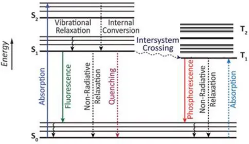
All these possible deactivation pathways of the fluorescent molecule on photo-excitation are best represented by a well known Jablonski diagram (Figure 1). In this diagram, the singlet electronic ground state is depicted by S0, singlet excited states by S1,S2….., triplet excited states
by T1, T2,……Accordingly, the absorption occurs very fast 10-15s so there is no displacement
of nuclei as stated by Franck-Condon principle.48
Figure 1 Jablonski diagram showing the radiative and non radiative processes in the electronic system of molecules during photoexcitation. 48
Fluorescence occurs during the transition of electron from the singlet excited state to the ground state of the opposite spin. The process is very fast and occurs in 10-8 s-1 since, the
17
transition is spin allowed. Fluorescence is independent of the excitation wavelength and is located at higher wavelengths than the absorption due to some loss of energy during vibration. The difference in the maximum of the absorption and emission is described as Stokes shift. Due to the different electronic distribution in the excitation state, the dipole moment of the fluorophore changes accordingly. Solvent effected excited state reactions and the complex formation can also alter the Stokes shift. Stokes shift can explain the behaviour of the excited states, higher the Stokes shift, better the detection of fluorescent species.
The fluorescence of a molecule is determined by quantum yield (ɸF ). ɸF of the fluorescence
can provide the essential information about the interactions of the excited state molecule with the surrounding medium. ɸF represents the fraction of excited molecules responsible for the
fluorescence, since all excited molecules do not necessarily deactivate through fluorescence. Because of the Stokes shift, ɸF cannot be equal to unity but close to unity if the non-radiative
decay is much smaller e.g. rhodamines
Mathematically, ɸF can be calculated using the following equation
Where ɸF is the fluorescence quantum yield, and are the rate constants of the radiative
and non-radiative deactivation from S1 to S0, is the lifetime of the excited state and τ is the
emissive rate.
The lifetime (τs) of the fluorophore is one of key characteristic of the fluorescence. It depends on the average time which the molecule spends in the excited state and is given by
Where τs is the life time of the excited state, krs and knrs are the rate constants of the radiative
and non-radiative transitions respectively.
The lifetime is generally independent of the excitation wavelength and lasts tens to picoseconds to hundreds of nanoseconds. However, the life time of the triplet excited state is larger than the singlet excited state. The temperature can affect both the quantum yield and the life time of a fluorophore. Accordingly, ɸ and τs decreases on increasing the temperature due to the thermal collisions and vibrations which favour the non-radiative deactivation.49
18 1.2.1.1. Fluorescence quenching
The quenching of fluorescence results in the decrease of the emission intensity. Quenching occurs through different mechanisms including collision, formation of non-fluorescent probes on interaction with quenchers, self quenching (excimer) etc. Collisional quenching occurs during the interaction of the excited state with the external molecule known as quencher. The decrease in the intensity due to quenching is given by a well known Stern-Volmer equation 49
Where F0 and F represent the fluorescence in absence and presence of the quencher
respectively, K is the Stern-Volmer constant, kq is the quenching rate constant, τ0 is the
lifetime of the non-quenched deactivation and [Q] is the concentration of the quencher. The Stern-Volmer constant K is given by the slope of the I0/I as a function of the quencher
concentration [Q]. The constant K defines the sensitivity of the fluorophore towards the quencher. The quencher can be in the form of different molecules like oxygen, halogens, amines etc.49
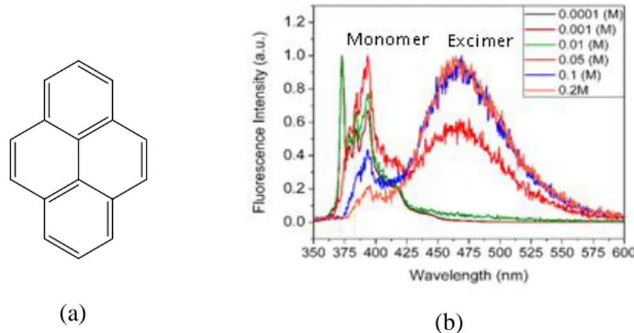
The formation of excimer (excited state dimer) at higher concentration changes the fluorescence band to the higher wavelength than the monomer. The excimer is formed between the excited molecule and the unexcited molecule of the same fluorophore and the process is very rapid. Furthermore, the emission spectra band can be differentiated from the excimer band since, the latter is without the vibronic peaks (Figure 2).50
(a)
(a)
(b)
Figure 2 (a) Structure of pyrene and (b) fluorescence of the pyrene showing increase in excimer intensity on
19 1.2.1.2. Phosphorescence
Phosphorescence occurs when the excited electron in the triplet excited state returns to the singlet state with same spin. Such transition is spin forbidden and hence takes due to spin-orbital coupling, making it a slower process (103-100 s-1).51 At room temperature, phosphorescence is absent in solutions since there are many deactivation processes that compete with the phosphorescence. Phosphorescence is bathochromically shifted than the fluorescence and the rate constant for such emission is higher than the latter. The phosphorescence can be enhanced by the incorporation of heavy atoms including bromine, iodine etc. since they favour the intersystem crossing.52
1.2.1.3. Non-Radiative pathways of deactivation
Many non-radiative processes including internal conversion, intersystem crossing can compete with the fluorescence of the molecule.48 Internal conversion occurs during the transition of an electron from the higher vibrational level of excited state to lower vibrational level of the S1 state of same spin multiplicity at the rate of 10-13 s to 10-11 s.
The other non-radiative pathway that competes with the fluorescence is the inter system crossing. Such transition occurs from the first excited state, S1 to the triplet state T1, having
isoenergetic vibrational energy levels. The process is faster (10-7-10-9 s) than fluorescence and internal conversion and is favoured by the spin-orbit coupling, since, it is spin forbidden. In addition to these processes, sometimes other undesirable processes similar to fluorescence results at higher time scale, described as delayed fluorescence.51 During this process the transition occurs from T1 –S1. This is possible only if the energies of these two states are
comparable or when the life time of triplet state is higher. This process is rare or completely absent in the aromatic hydrocarbons due to large energy difference between T1 and S1.
1.2.1.4. Types of fluorescent molecules
Fluorescent compounds can be organic (aromatic hydrocarbons, fluorescein, rhodamines, coumarins etc.) (Figure 4), inorganic luminescent compounds (uranyl ions, crystals of ZnS, CdS etc.) or organometallic complexes particularly based on platinum, ruthenium etc. The most common fluorophores are typically aromatic in nature including 1-4, bis(5-phenyloxazol-2-yl)benzene (POPOP), quinine sulphate, fluorescein, acridine orange,
20
rhodamine B, pyridine 1 etc. (Figure 3). The significant applications of these fluorophores have been intensively investigated and reported.53–56 For example pyridine 1 and rhodamine are function as laser dyes, solutions of quinine sulphate work as standard for quantum yield calculations.57,58 The other kinds of fluorophores that are intensively investigated belong to polynuclear aromatic hydrocarbons like anthracene, perylene etc. These fluorophores have potential ability for the application of sensors for oil pollution and other areas.
Figure 3 Structures and the fluorescence of some typical aromatic fluorescent molecules under the illumination
of UV light.49
1.3. Fluorescent Molecular Rotors
Fluorescence of some fluorophores depends on the structure and flexibility of their molecules. Among these molecules are well known special type of fluorophores whose fluorescence is highly dependent on their structure and flexibility and are known as Fluorescent molecular rotors (FMRs). Typically, FMRs undergo intramolecular twisting in the excited state.59 FMR typically consist of than electron donor moiety, and an electron acceptor moiety joined together by conjugated electron rich unit.59 Accordingly, the electrons are transferred from the donor to the acceptor through the conjugated system during photoexcitation. During the charge transfer from donor to acceptor moiety, the intramolecular twisting of the side groups occurs due to electrostatic forces described as twisted
21
intramolecular charge transfer (TICT) (Figure 4).60 The FMR thus assumes a non-planar configuration in the excited state from planar configuration in the ground state. The twisted ground state has higher energy and always has natural tendency to return to the less energetic planar ground state. The energy of TICT state is lower than the locally excited (LE) state and hence the energy barrier to change from LE to TICT needs to overcome. The energy barrier between the locally excited state (LE) and TICT is strongly influenced by the surrounding medium including viscosity and polarity. The deactivation process of excited molecules from TICT conformation results in the decrease of emission intensity or complete nonradiative transition depending on the energy gap between the twisted excited state (S1) and ground
state (S0 ), which in turn depends on the molecular structure and the surrounding medium.61,62
It must be noted that there are two types of deactivation processes in FMRs depending on the structure of the molecular rotor. Accordingly some FMRs exhibit dual emission related to LE and TICT conformations. For molecular rotors with emission from the twisted state with bathochromic shift, steric hindrance of TICT formation results in the emission from LE state.63 However, the molecular rotors with non radiative deactivation from twisted state, steric hindrance only increases the fluorescence without altering the shift.64
Polarity of the medium can also influence the deactivation process in some FMRs by favouring stabilization of TICT state.65 The formation of TICT actually results in the unbalanced increase of dipole moment during photoexcitation. Alternatively, the dipole moment of polar solvent molecules reorients with that of the FMR molecules and is described as solvent relaxation. Consequently, this results in the decrease in energy of the excited state confirmed by the red-shifted fluorescence.
The Jablonski diagram depicting the photophysics of FMRs is modified by altering the energy gap between the excited and ground states (Figure 5). The degree of the intramolecular rotation determines the ground and excited state energy levels. Notably, the ground state is associated with the planar conformation while as twisted conformation is preferred for the excited state.
22
Figure4 Representation of Twisted intramolecular charge transfer (TICT) in p-N,N–dimethylaminobenzonitrile
(DMABN)52
Figure 5 Jablonski diagram for FMRs showing TICT dynamics. (D and A represent donor and acceptor
moieties respectively)66
Most commonly known FMRs are based on nitriles such as 1,4 dimethylamino benzonitrile (DMABN), Julolidine derivatives such as 9-dicyanovinyl julolidine (DCVJ) and stilbenes such as p-(dimethylamino) stilbazolium (p-DASMPI, D) (Figure 6). The significant importance of these FMRs is indicated by their potential application in detecting microviscosity in biological systems 59. It is noted that DMABN allows emissive relaxation due to higher energy gap between the ground and first excited state. Furthermore, the molecule also emits from the LE state with red-shifted fluorescence. The relative intensity of the two emission bands is determined by the formation of TICT state. On the other hand the twisted state of DCVJ is specified by much smaller S1-S0 energy gap thereby favouring
nonradiative relaxation of the molecule in non-viscous solvents.62 Such types of FMRs do not display second emission band.
23 (a) (b) (c)
Figure 6 Typical structure of some FMRs (a) 1,4 dimethylamino benzonitrile (DMABN), (b) 9-dicyanovinyl
julolidine (DCVJ) (c) p-(dimethylamino) stilbazolium (p-DASMPD) The arrows represent the rotating moieties of the molecule.59
1.3.1. FMRs based on julolidine
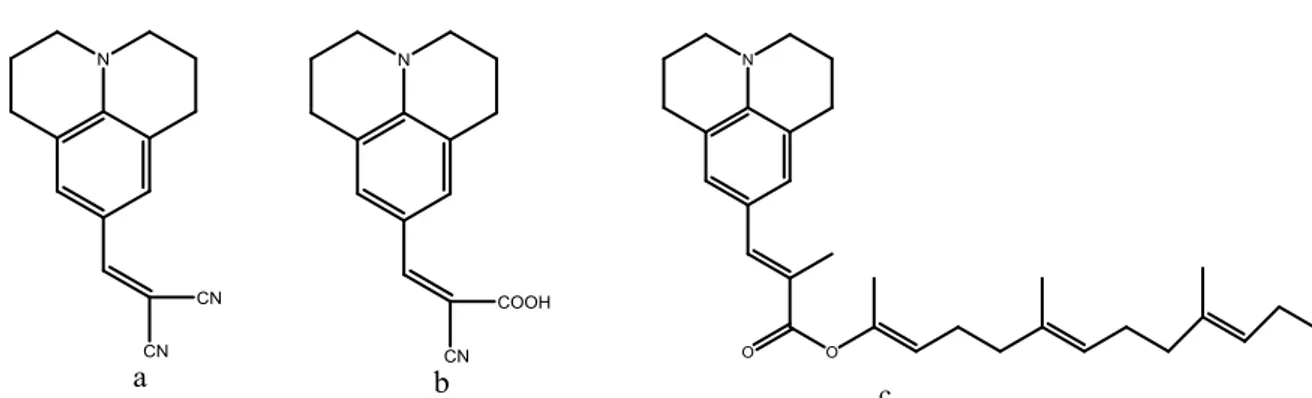
Julolidine derived FMRs are among the highly investigated FMRs reported to have significant biological applications for measuring the viscosity dependent changes.52,67,68 Some common Julolidine derived FMRs reported to display the microviscosity changes in the biological systems include [(2-cyano-2-hydroxy carbonyl) vinyl] julolidine (CCVJ), 9-(dicyanovinyl) julolidine (DCVJ), 2-carboxy-2-cyanovinyl julolidine farnesyl ester (FCVJ) etc. (Figure 8).69,70
Typically they belong to the group of benzylidene malonitriles and charge transfer usually takes place from the nitrogen atom to electron acceptor nitrile group through the benzylidene moiety (Figure 7). The presence of nitrogen atom within the fused ring system hinders the rotation of C-N bond and increases the energy gap between LE and TICT. It is noteworthy that on excitation, the C=C vinyl bond exhibits single bond character and is responsible for the nonradiative deactivation in julolidine based FMRs. The quantum mechanical calculations also supported the view that the excited state rotation across the C–C is not favoured energetically compared to the rotation in the ground state. Contrary, the rotation of C=C is hindered in the ground state and is favoured in the excited conformation. The rotation around the vinyl double bond could result in the isomerisation of the molecule and thereby compete with the deactivation process of the FMR.62
24
moiety with carboxylic group allowing addition of different hydrocarbon chains (R) was reported by Haidekker et al.52 Different water soluble julolidine derivatives were synthesized from non-soluble DCVJ with promising application in aqueous colloidal solutions and biofluids.71 On one hand, the incorporation of side chains enhance the solubility in polar and non polar solvents while the replacement of the functional groups can wider the application without interfering the viscosity sensitivity of the molecular rotor.69,72
Figure 7 General Structure of the julolidine based FMR showing rotor part and the variable group .The colours
represent different functions of FMR (green represent electron donor, blue conjugated part and red electron acceptor.
Figure 8 Structure of julolidine FMRs used to detect microviscosity in biological systems. (a) DCVJ, (b)
CCVJ, and (c) FCVJ70
1.3.2. Applications of FMRs
The effect of viscosity and polarity on the formation of TICT in FMRs has attracted the attention of researchers for the wide range of applications particularly in determining the local microviscosity. The effect of viscosity on DCVJ can be realised in the solution using the mixtures of solvents with much different viscosities. For example the mixture of ethylene glycol and glycerol when mixed in different proportions result in the solutions with wide range of viscosities. Accordingly, DCVJ experienced higher fluorescence in the mixtures with higher viscosity and vice versa (Figure 9).
25
The dynamics of FMRs in sterically restricted environment has been reported to be useful for the fluorescence imaging in biological systems. The research interest of studying viscosity changes in biological systems is very useful, for example, the changes in the cellular membrane microviscosity can directly affect the cellular functioning resulting in some diseases.70,72
The application of fluorescent based molecules for measuring the local viscosity is favoured by the higher spatial resolution time and the fast response. Fluorescence anisotropy and fluorescence recovery after photobleaching (FRAP) methods have been already used for the estimation of viscosity changes.73,74 However, their application is limited due to the requirement of the specific equipment and the lower resolution.
FMRs based on julolidine derivatives are reported to serve as smart tools for the detection of microviscosity changes in biological systems, thanks to their higher sensitivity, better resolution etc. The fluorescent properties of these molecular rotors is strongly enhanced by small changes in viscosity.66 Furthermore, the stability of FMRs against photo bleaching also support their application in measuring the precise viscosity changes.72 FMRs are considered as a better alternative to mechanical rheometer to detect the viscosity in biological systems, as the latter is time consuming and limited to bulk volumes.59 Besides, after using the mechanical viscometer, complex cleaning process becomes another limitation as proteins adhere to the walls of the instrument.69 On the other hand the amount of sample required for determination of viscosity by FMRs is very less (micro litre) and also allows the real time monitoring of the micro viscosity changes. Furthermore, the viscosity measurement by FMRs can meet the precision and accuracy to that of the mechanical viscometers.69
Figure 9 Emission spectra (solid lines) of DCVJ in different mixtures of ethylene glycol and glycerol. The
dashed lines indicate the excitation spectra.69
The quantum yield of the FMRs depends on the molecular structure of the molecule. For example, the viscosity sensitivity of CCVJ is higher than DCVJ in the same viscous
26
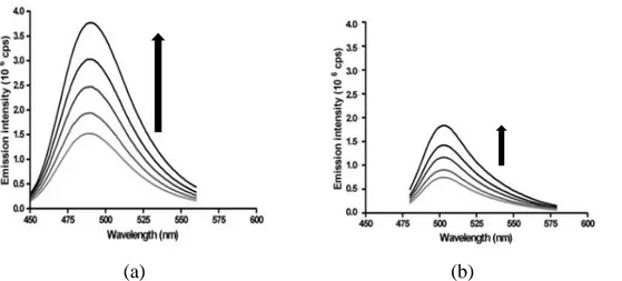
medium52 and thus the fluorescence of the former is higher than the latter (Figure 10). Accordingly the quantum yield of CCVJ is reportedly higher than DCVJ.
(a) (b)
Figure 10 Emission spectra of (a) CCVJ (b) DCVJ in mixture of ethylene glycol with different fractions.
Arrows represent the increase in fluorescence in similar viscous solvents.52
The relation between the viscosity and the quantum yield is given by the Forster –Hofmann equation69
Where C is the temperature dependent constant, the constant x depends on the dye, η is the viscosity and ɸ is the quantum yield.
The emission intensity and the quantum yield are directly and proportionally related as Iem α Iabɸ,
Where Iem and Iab represent the emission and absorption intensities respectively and ɸ is the
quantum yield.
The viscosity sensitivity of FMRs has also been explored for the determination of the molecular weight and tacticity of the polymers.75 Actually, the free volume of the polymer depends on the molecular weight and can therefore directly influence on the quantum yield of the FMRs. This suggests the possible application of FMR for the determination of the polymerization process. Fluorescent molecules can also work as real time monitoring of the polymer dynamics.76 The other applications of FMRs in polymers include determination of degradation, thermal transitions, crystallization, swelling etc.77
27
1.3.3. Effect of polarity on FMRs
The effect of polarity on the fluorescence of FMR is a complex issue and is still under investigation. It was believed primarily that FMR cannot be sensitive to both viscosity and polarity since the role of intramolecular charge transfer (ICT) is hardly evident in their excited state. Accordingly, if a FMR is sensitive to viscosity, polarity changes will not affect the fluorescence behaviour and vice versa.69,78 However, contrary to this, it was reported that by tuning the electron donating ability of the substituents in fluorophore, the effect of ICT can be induced. Zhaou et al. designed many new FMR, 2-(4-(diphenylamino) benzylidene) malonitrile, a derivative of triphenyl amine (TPA), displayed sensitivity to both viscosity and polarity thereby depicting the role of ICT (Figure 11).78 This behaviour is ascribed to the configurational transformation of TPA as well as the larger size of the rotor molecule. After photoexcitation, the solvent molecules reorient themselves around the FMR and interact by van der walls or hydrogen bonding depending on the solvent. Consequently, there is some energy transfer from the excited state of the molecule to the polar solvent molecules resulting in the red-shift of the emission spectra.68 Also, the formation of TICT is favoured in higher polar solvents and vice versa. Unlike many fluorescent probes, like coumarin derivatives, julolidine derived FMRs are less sensitive to the polarity changes (Figure 12). Notably, this is the result of less favourable intermolecular charge transfer in the julolidine based FMRs.
(a)
(b)
Figure11 (a) Structure of 2-(4(diphenylamino)benzylidene) malonitrile and (b) its emission spectra in solvents
28 (a) (b) (c) (d)
Figure 12 (a) Structure and (b) fluorecsence of coumarin 1 in different solvents, (c) structure and (d)
fluorescence of DCVJ in the similar solvents.68
1.3.4. Fluorescent molecules as vapochromic sensors
The spectroscopic change that occurs due to interaction of vapochromic material with VOC is termed as “vapochromism”. Vapochromic materials change colour on interaction with volatile organic compounds (VOCs), making it possible to detect their presence by naked eye.79 Considering the harmful effects of the VOCs, the researchers are actively involved in the development of vapochromic sensors for their easy and simple detection (Fig. 13).
29
Different classes of fluorescent materials have been developed as vapochromic sensors. These materials can either belong to organometallic complexes or organic dyes. Vapochromic organometallic compounds belong to platinum (II), palladium (II), gold (I), zn (II) etc. Among these organometallic complexes, vapochromism of platinum(II) compounds have been highly investigated.79,80 Lu et al. reported the vapoluminescent materials of [pt-
t
Bu2bpy)arylacetylide)2 complexes (Figure 14a) with different acetylide groups as 4-pyridyl,
3-pyridyl , 2-pyridyl, 4-ethynylpyridyl, 2-thienyl and pentafluoro. The solid state emission was reportedly dependent on the crystalline structure of the complexes. Films of each complex responded differently when exposed to similar solvents.81 On exposure to dichloromethane, fluorescence intensity increased drastically. In the crystal structure with acetylide as 4-pyridyl, it was noted that dichloromethane molecules interact with bis(acetylide) moiety through C-H….π(C≡C) interactions . On evaporation of the solvent, the intensity decreased gradually confirming the reversible vapochromic response of the fluorophore (Figure 14b).
(a) (b)
Figure 14 (a) Structure of [pt- tBu2bpy)aryl 4-pyridyl)2 and (b) fluorescence of the film of this complex on
exposure to saturated dichlomethane vapours (Inset b) shows the emission spectra of the film on the removal of the dichloromethane from the film.81
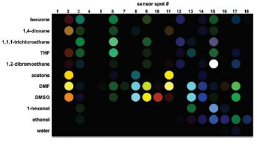
Wang and co-workers reported the reversible vapochromism of platinum (II) complex Pt (dbbpy) (C≡CC6H4bMes2)2 upon exposure to different VOCs.82 The system exhibited
complex fluorescence shifts based on interaction with solvents of different polarity. Solvents including dichloromethane chloroform, acetonitrile, THF, acetone induce a shift from yellow to green while benzene, 1,4-dioxane result in the red-shift emission (Figure 15).82
30
Figure15 Vapochromic behaviour of Pt (dbbpy) (C≡CC6H4bMes2)2 films on exposure to different solvents
(Left). Molecular structure of Pt (dbbpy) (C≡CC6H4bMes2)2. (Right)82
The vapochromic behaviour of many fluorophores has been investigated in different polymer matrices. An interesting vapochromic behaviour was reported on exposure of the PMMA films containing square-planar Pt(II) complexes of 4-dodecycloxy-2,6-bis(N-methylbenze imidizole-2'-yl) pyridine (1), to the vapours of acetonitrile (Figure 16a).83 Notably, the colour of the film changed from yellow to orange red before and after exposure respectively (Figure 16b (inset). The emission intensity of the dye/polymer system increased drastically on exposure to acetonitrile thus making it suitable sensor for the detection of the solvent (Fig 16 b). (a) (a) (b)
Figure 16 (a) Molecular structure of the [Pt(1)Cl](PF6) (b) Vapochromism of 10wt% [Pt(1)Cl](PF6) in
PMMA on exposure to acetonitrile for 900s under the UV lamp excitation at 377nm. (Inset b) Images of the dye/polymer films before exposure (yellow) and after exposure to CH3CN (orange red) after 900s.83
31
Recently the vapochromic behaviour of the Zn(II)-bisthienylethynylbipyridine complex (Figure 17a) in poly(methyl methacrylate) (PMMA) films was reported by Irina et al.84 The presence of thienylethylene moieties maintain the π electronic conjugation and the heteroatomic rings are supposed to hinder the intermolecular interactions based on π-π stacking. The complex on exposure to VOCs indicated sensitivity to both polarity and the viscosity (Figure 17b). The polarity sensitivity was addressed to the ICT character of the complex favouring the reorganization energy of transition on increasing the polarity. The decrease in viscosity inside PMMA matrix was attributed to the diffusion and swelling on exposure to dichloromethane favouring the better salvation of the Zn(II) complex. The solvation of the complex also decreases the energy gap of the different electronic states and thus speedup the electron transfer rate which in turn accelerated the relaxation to non emissive state. The simplicity and cost effectiveness of the method opens new ways to detect the VOCs by fluorescent molecules using polymers as supporting materials.
(a) (a)
(b)
Figure 17 (a) Structure of 6,6'-(Bis 5-methylthiophen-2-yl)ethynyl)-2,2'-bipyridine (b) Fluorescence of 0.5wt.%
of a:Zn/PMMA on exposure to dichloromethane indicating vapochromic behaviour of the dye.(Inset b) Change in the maximum emission wavelength as a function of exposure time depicting the bathochromic shift.84
1.3.5. FMRs as vapochromic sensors
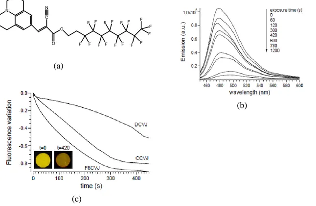
The better sensitivity of FMRs towards viscosity and polarity as explained before is explored for the application of vapochromism. The dynamic features of these moleculecular rotors render them potential candidates for the VOCs sensing ability. The vapochromic behaviour of few FMRs has been already investigated successfully. Martini et al. explored the vapochromic application of viscosity sensitivity julolidine derived FMRs including DCVJ, CCVJ and9-(2-(1H,1H,2H,2H-perfluorodecyloxycarbonyl)-2-cyanovinyl) julolidine (F8CVJ) dispersed in polystyrene (PS) films (Figure 18a).85 Different FMR/polystyrene films were
32
prepared by solution casting with 0.1wt. % of the fluorescent dyes in each film. The FMR/PS films on exposure to well polymer interacting solvents (chloroform and toluene) favoured the TICT of FMRs resulting in diminishing of intensity (Figure 18b). Eventually, the formation of TICT is supported by the relaxation of macromolecular chains due to solvent molecules, resulting in greater mobility with increase in free volume. Consequently, this leads to the decrease in viscosity inside the polymer matrix. It was noted that F8CVJ performed better than DCVJ and CCVJ and was attributed to the preferential molecule concentration in outer layer of polymer film (Figure 18c). This effect is caused by the selective segregation of fluorinated fluorophore thereby enabling F8CVJ to interact more easily with vapours. The solvents which were unable to interact with PS displayed no vapochromic response.
(a)
(c)
(b)
Figure 18 (a) Molecular structure of F8CVJ (b) Change in Fluorescence of 0.05%wt of F8CVJ/PS films on
exposure to chloroform (c) variation of fluorescence maximum intensity as a function of time of 0.05wt% DCVJ,CCV,F8CVJ in PS on exposure to chloroform, inset (c) Images of F8CV/PS films with 0.05wt% FMR before and after exposure to CHCl3 under UV lamp excitation.85
Recently, the vapochromic behaviour of jolulidine–containing styrene copolymer was reported by some workers in our group with significantly faster response.86 Accordingly, poly(styrene-co-hydroxyethylmethacrylate) copolymers were functionalized with cyanovinyl-julolidine to prepare (polystyrene-co-2-methylacryloxy) ethyl-2-cyano-3-julolidin-acrylate (P(STY-co-JCAEM) (Figure 19a) and their vapochromic behaviour was investigated.
33
Interestingly during exposure to VOCs, the fluorescence decrease was much faster (Figure19b) reasonably due to the homogeneous JCAEM moieties distribution favoured by covalent bonding between the FMR and the polymer.
Figure 19 (a) Structure of P(STY-co-JCAEM) and (b) Fluorescence of P(STY-co-JCAEM) film on exposure to
chloroform, indicating fast vapochromic response. 86
1.4. Aggregation induced emission (AIE) in fluorophores
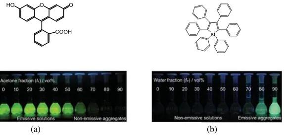
Aggregation of most of the fluorophores results in quenching of the fluorescence and is known as aggregation caused quenching (ACQ). When fluorophores aggregate together, there is the possibility of the intermolecular π-π interaction which results in quenching of fluorescence.87 For example, fluorescein is a typical ACQ fluorophore and is insoluble in many organic solvents but dissolved in water. Consequently, in organic solvents like acetone, the fluorophore aggregates and becomes non-emissive in contrary to highly emissive in water (Figure 20a). Accordingly, the planar polycyclic aromatic structure of the fluorescein favours the aggregate formation due to the π-π stacking resulting in excimer formation and thereby causing ACQ. The non-emissive deactivation of such fluorophores limits their application in real-world technology. For example, ACQ effect limits the application of fluorescent materials in the fabrication of optoelectronic devices like organic-light emitting diodes and other practical applications.87,88 However, the aggregation cannot always result in the fluorescence quenching. Some fluorophores become highly emissive on aggregation and such phenomenon is known as aggregation induced emission (AIE) and the molecules depicting such behaviour are termed as AIEgens. AIEgens are actually special type of FMRs and were first reported by Ben Zhong Tang and co-workers.88 They reported a series of silole
(a) (b)
34
derivatives which were non-fluorescent in dilute solutions and highly emissive in aggregate form. The AIE effect was first discovered in Hexaphenylsilole (HPS), a propeller and non-planar molecule. The phenyl rotors in HPS undergo intramolecular rotations in dilute solution resulting in the non-emissive deactivation transition on photoexcitation (Figure 20b). However, on aggregation in poorly soluble solvents, the π-π interaction is avoided due to the non-planar structure and propeller shape.89 On the other hand, the intramolecular rotation of the aryl groups is restricted and such process is known as restricted intramolecular rotations (RIR) (Figure 21a). It is this RIR phenomenon that is supposed to be responsible for the AIE in HPS and other such luminogens. This fact was further supported by measuring the fluorescence of HPS in viscous solvents at lower temperature and higher pressure.90–92 A large numbers of AIEgens have been synthesized and their potential application in different areas has been highly investigated. For example tetraphenylethylene (TPE) is one such highly investigated AIEgen with broad range of applications reported.87,93 TPE display typical structural features with four phenyl rings attached to the central ethylene rod through single bond makes. In dilute solution the phenyl rings freely rotate against the ethane rod serving as the non-radiative path for deactivation. Contrary, in the aggregated form, RIR of the phenyl rings favour the highly emissive behaviour of TPE. (Figure 21b).94
(a)
(b)
Figure 20 (a) Structure and fluorescence of fluorescein different water/acetone mixtures with variable fractions
and (b) structure and fluorescence of hexaphenylsilole (HPS) in water/THF mixtures of different fractions.87
35 (a)
(b)
Figure 21 Representation of the restricted intramolecular rotation (RIR) aggregation in (a) hexaphenylsilole
(HPS) 93 and (b) tetraphenylethylene (TPE).95
1.4.1. Application of AIEgens
The effect of concentration quenching restricts the application of fluorophores for desired purposes. On the other hand quantum dots are considered as better alternative to overcome such restrictions, however, the difficult synthesis, limited variety and toxicity makes them unsuitable for the desired applications.96,97AIEgens are reported to overcome all such limitations since there is no concentration quenching or toxicity effects related to these luminogens. The AIE effect is suitable to work where the ACQ effect fails. Soon after the discovery of AIE in 2001, interest for developing new AIEgens with fascinating applications has gone up too rapidly. AIEgens with large scale applications in biological imaging, photodynamic therapy, chemical detection, optoelectronic device fabrication etc. have been successfully developed and investigated (Figure 22).98–105
Certain luminogens like HPS are reported to display interesting features for sensing applications including viscochromism, piezochromism, and thermochromism.106 Viscochromism effect is due to enhancement of RIR in higher viscous solvents and hence increasing the fluorescence. Pressure sensitivity of HPS is assumed due to the compression, bringing molecules together resulting in hindrance of the rotation of the phenyl rings. However at much higher pressure the formation of excimer can decrease the emission. Temperature sensitivity of HPS recorded in THF indicated the potential application of
36
AIEgens for thermochromism. Since, cooling hinder the thermally allowed intramolecular rotations, the HPS solution in THF resulted in intensified emission on cooling.
Figure 22 Structure and real-world applications of some AIEgens.95
1.4.2. AIEgens as VOCs sensors
TPE derived AIEgens also demonstrate exhibit solvatochromic behaviour enabling their application for measuring polarity changes. Tang et al. reported the solvatochromic behaviour of the 1,3 indandione–modified TPE (IND-TPE) (Figure 23a,b).87 1,3-indadione acts as an electron acceptor and its attachment with TPE core results in a push-pull chromophore due to ICT phenomenon. On changing the solvent from toluene to acetonitrile, a bathochromic shift from 543 to 597 nm was recorded (Figure 23c). Such kind of application allows measuring the AIE and polarity changes without affecting the photophysical properties of AIEgen.
37 (a)
(c)
(b)
Figure 23 (a) Structure of 1,3 indandione modified –tetraphenylethylene (TPE), (b) Fluorescence of
IND-TPE in different solvents showing solvatochormic behaviour and (c) Images of IND-IND-TPE solutions in different solvents under the UV lamp illumination at 365nm.87
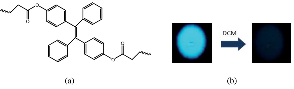
The potential applications of AIE as vapochromic sensor was recently extended to polymeric systems.107 The detection of VOCs using TPE/Polymer systems were investigated by Tang et al.108 Polyacrylates were prepared through radical polymerization of the TPE containing di-and tetracrylates (Figure 33a). The TPE/Polymer system on exposure to dichloromethane showed excellent reversible vapochromic response (Figure 34b).
(a) (b)
Figure 24 (a)TPE-attached to polyacrylates and (b) Images of the spots of the polymer on thin layer
38
1.5. Solvatochromic probes as sensors for the detection of
VOCs
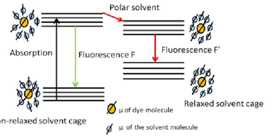
The change in colour of a chromogenic material on changing the polarity of the solvent is described as solvatochromism. The phenomenon was first termed by Hantz schlater109 however since then, the meaning of this term has broadened. Depending of the polarity index of the solvent, solvatochromism can be either positive or negative corresponding to bathochromic and hypsochromic shifts respectively.110 Solvatochromism occurs due to differential salvation of the ground and first excited state of the chromophore resulting in the stabilization of either of the two states. Accordingly when excited state is more stabilized than the ground state in higher polar medium, bathochromic shift occurs and vice versa.110 Since the absorption process is very fast than the time required for the displacement of nuclei (Franck Condon principle) and results in redistribution of electrons and consequently changes in dipole moment. Like FMRs, solvatochromic molecules also contain both donor and acceptor moieties connected by conjugated part. However, their flexibility is restricted even in the free environment. The ICT chromophores, also known as push-pull chromophore, are simply represented by an electron donor (D) linked to an electron acceptor (A) through π-conjugated linker having dipole character.111 This ensures that during photoexcitation, the charge is transferred from donor to acceptor forming a excited state with higher dipole moment (μ). Consequently, the excited state then relaxes through interaction with the solvent dipoles resulting in bathochromic shift in polar solvents as represented. Due to the ICT, the dipole moment increases in the excited state (μe) with respect to the dipole moment of the
ground state (μg) on photoexcitation.110,112–114 The polar solvent molecules are assumed to
form a cage around the solavtochromic dye molecule which then undergoes relaxation to the minimize energy of the excited state of solute molecules (Figure 25). Since the lowering of the energy is much larger in higher polar solvents than the lower polar solvents, bathochromic shift results in polar medium. When the lifetime of the solvent reorganisation around the chromophore is shorter than excited state lifetime, fluorescence results from the molecules in equilibrium with salvation shell (F' in figure 25). In case of the higher polar solvents the bathochromic shift is accompanied by non radiative emission due to higher decrease in energy of the chromophore. Higher viscous solvent may hinder the solvent reorganization112 thereby resulting in emission from Franck Condon state with a slightly
39 shifted emission spectra.
Figure 25 Representation of solvent cage around the salvatochromic dye with the orientation of the dipole
moment in non-polar (left) and polar solvent (right).51
Solvatochromism depends on the chemical and physical properties of the chromophore as well as the solvent that together describe the strength of intermolecular solute-solvent interactions. The exact environmental effects of a solvatochromic probe are still under investigation.
The sensitivity of chromophores to the polarity of the medium is explored for the development of novel sensors for the detection of solvents based on their polarity. The solavtochromic probes have been also used to monitor biophysical properties of biomembranes including polarity which play important role in organization and function of these membranes.115 Loew et al. use styryl-pyrinidium, charge transfer dyes, to detect transmembrane potential since they are vertically oriented in biomembranes.116 Solvatochromic probe has also proved as powerful tool to detect bimolecular interactions with better response than fluorescence resonance energy transfer (FRET) and fluorescence anisotropy.117
The typical polar sensitivity of different solvatochromic probes has been explored for chemical sensing applications. For example Prodan, Nile red, Dapoxyl derivatives etc. (Figure 26) display typical solvatochromic behaviour and have demonstrated the chemical sensing ability. With the time, the solvatochromic features of the chromophores have been enhanced by certain modification methods. Recently, Kucherek et al. developed fluorene analogues of prodan (7-diethylamino-9,9-dimethyl-9H-fluorene p-2-carbaldehyde, (FR0)) by