Università Politecnica delle Marche
Facoltà di ingegneria
Scuola di Dottorato di Ricerca in Scienze dell’Ingegneria
Curriculum in:
Ingegneria Civile, Ambientale, Edile e Architettura
XXX° ciclo
A mechanically derived vulnerability index method for
seismic risk assessment of existing RC school buildings
Candidato
Tutor
Acknowledgments
I wish to express my deep gratitude to my supervisor Prof. Stefano Lenci for the opportunity he gave me to take part to the Ph.D. course and for the support constantly provided during the period of my research work.
Particular thanks are due to Francesco Clementi, researcher at the Università Politecnica delle Marche, for the help provided to me in many situations.
I would like to thank the provinces of Ancona and Macerata for the documentation made available relatively the high school buildings.
A mamma,
papà,
Rosanna e
Maria Lucia
Abstract
The seismic vulnerability of RC school buildings is a very important issue in Italy, as shown from the recent earthquakes (Molise 2002, L’Aquila 2009 and Amatrice 2016) causing the collapse and heavy damage of several school buildings. Most of Italian schools were built between the 50s and the 90s and so were usually designed considering only vertical loads, without or with low seismic resistance criteria.
In this study a methodology for rapid risk assessment of RC school buildings is shown. It is based on the vulnerability index method, considering 15 vulnerability indicators to which assign scores on the base of expert judgment. The scores were determined through pushover analyses performed on several structural models representative of the main characteristics of the Pre and Post 1974 school building stocks. To this aim a set of about 40 high schools (for a total of 105 independent buildings) were analysed to determine typical and specific vulnerabilities, and a simulated design procedure was carried according to the Codes in force in the two reference periods.
Correlations between the global vulnerability index Iv and the capacity in terms of PGA, for both
slight damage and collapse, were determined to obtain trilinear damage curves such as in the 2nd
level GNDT method.
Numerical validation of the rapid method was made by comparing the trilinear damage curves obtained for the two prototype buildings, representative in average of the Pre and Post 1974 school buildings, with analytical curves provided by both pushover and incremental dynamic analyses. Also, experimental validation was carried out by comparing, for every high school building of the provinces of Ancona and Macerata, the damage occurred because of the Centre Italy 2016 seismic sequence with the damage estimated for the same intensity level through the proposed method. Both validation procedures have confirmed a good reliability of the proposed method for rapid and comparative evaluations.
Then two typologies of rapid damage scenarios were developed for both building stocks, in order to estimate physical, human and economic losses. The first typology considers uniform hazard on the whole territory and increasing intensity levels, instead the second one considers single events on the base of the fault system of the region (epicentres, magnitude and depth), thus the PGA values are calculated by means an attenuation law.
CONTENTS
Introduction 1
1. Seismic vulnerability of existing buildings 4
1.1. General aspects 4 1.2. Seismic response of RCMF structures 11
References chapter 1 26
2. Methods for seismic vulnerability assessment of buildings 30
2.1. Rapid methods 34
2.1.1. Macroseismic methods 35
2.2. Analytical methods 52
2.2.1. Simplified nonlinear procedures 53
References chapter 2 65
3. Seismic risk assessment 71
3.1. General aspects 71
3.2. Methods for risk assessment 77
3.3. Seismic hazard 84
3.3.1. Intensity measure parameters 95
3.4. Physical damage 96
3.4.1. Fragility curves 101
3.5. Human and economic losses 104
References chapter 3 110
4. The RC school building stock 119
4.1. The RC school building typology 119
4.2. Description of the building stock 127
References chapter 4 137
5. Proposal of a vulnerability index method for RC school buildings 139
5.1. General criteria and definition of the parameters 139
5.3. Parametric analyses 150
5.3.1. Structural modelling and pushover analyses 150
5.3.2. Analysis results 155
5.4. Proposed method for school buildings 165
5.4.1. Iv – PGA relationship 171
References chapter 5 181
6. Rapid seismic vulnerability assessment for the school building stock 185
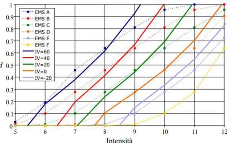
6.1. Assessment with macroseismic method 185
6.1.2. Macroseismic intensity – PGA relationship 189
6.2. Assessment with vulnerability index method 193
6.2.1. 2nd level GNDT method 194
6.2.2. Proposed method 197
6.2.3. Comparison between methods 204
6.2.4. Trilinear damage curves for the classes 215
References chapter 6 217
7. Numerical validation through nonlinear analyses 218
7.1. Assessment of the prototype buildings 219
7.1.1. Incremental dynamic analysis (IDA) 219
7.1.2. Pushover analysis 229
7.1.3. Comparison of the results 237
7.2. Assessment of case studies 240
References chapter 7 244
8. Experimental validation: the 2016 Centre Italy earthquake 248
8.1. The seismic sequence and the damage suffered to the building stock 248
8.2. Rapid damage estimation for the building stock 254
8.3. Analytical damage estimation for a case study 260
8.3.1. Non-linear dynamic analysis (NLDA) 263
8.3.2. Pushover analysis 267
References chapter 8 271
9. Rapid damage scenario for the building stock 274
9.1. Seismic hazard of the region 275
9.1.1. Determination of the seismic intensity level 280
9.3. Uniform hazard scenarios 289
9.4. For single event scenarios 297
References chapter 9 311
Conclusions 313
1
Introduction
The work illustrated in this Ph.D. thesis born from the needed to rapidly assess the seismic safety level of the widespread Italian school building heritage, in order to carry out risk mitigation interventions.
In fact, recent earthquakes (Molise 2002, L’Aquila 2009 and Amatrice 2016) highlighted the quite high vulnerability of this building typology. Further, recent studies and reports about school buildings provided a general unsafe condition.
This problem, in general, involves the whole Italian built heritage because the most part was built in absence or with low seismic resistance criteria during the period 50s – 90s, when Old Seismic Code were in force and the seismic classification of the territory didn’t consider the actual hazard. This mean that many reinforced concrete (RC) buildings were designed with low seismic detailing as the lack of stirrups in the column-beam joints, low quantitative of steel reinforcement in the columns leading to strong beam-weak column behaviour and many other structural irregularities (stiffness and resistance distributions).
Only after the 2003, a modern seismic Code was introduced, adopting the Capacity Design principles, and the seismic classification of the territory was improved leading to the Italy hazard map obtained by means a PSHA.
A depth description of these aspects is illustrated in chapter 1, where the seismic behaviour and main vulnerabilities of RC buildings are described.
In chapter 2 and 3 are shown the procedures to assess respectively the seismic vulnerability and risk. The latter involves also the seismic hazard and the exposure estimation.
In chapter 4 the school building topology is investigated referring to the RC high school building stock of the province of Ancona (105 RC independent structures). The main structural and morphological characteristics are detected, and the typical and specific vulnerabilities are shown distinguishing between PRE and POST 1974 classes.
The PRE 1974 class is representative of buildings designed according to the R.D. 2229 dated 1939, while the POST 1974 represents those designed according to law n. 1089 date 1971 and the relative successive Decrees.
The main differences between the two classes are in the:
• type of design adopted, considering only static load for the PRE 1974 buildings, while the seismic action is considered for most part of the POST 1974 buildings.
• Type of steel employed, smooth for the PRE 1974 and ribbed for the POST 1974 period. Then the practical aspects of the work (elaborations and results) can be summarized in two main parts:
2
1. The first part, in which a vulnerability index method for RC school buildings is developed (chapter 5) and validated by means both numerical (chapters 7) and experimental procedures (chapter 8). Further the evaluation of the building stock is made through the macroseismic method, referring to the EMS-98 scale, and the 2nd level GNDT and proposed methods (chapter
6).
2. The second part, in which rapid damage scenarios for the school building stock of the province of Ancona and Macerata were developed considering several intensity levels (chapter 9) and accounting for the exposure data as the scholar population and replacing cost of every school building.
The proposed vulnerability index method is mechanically-derived. In fact, many pushover analyses on 50 structural models with lumped plasticity, generated in a deterministic manner to represent the vulnerabilities detected for the PRE and POST 1974 classes and according to simulated design procedure, were carried out in order to compare the capacities of the models and so to determine the scores to assign to the vulnerability indicators. The capacity parameter assumed is the area comprised under the average equivalent bilinear curve of the 8 curves obtained for each model from the pushover analysis.
A total of 15 indicators are considered, against the 11 of the 2nd level GNDT method.
Also, relationships between the global vulnerability index (Iv) and peak ground acceleration (PGA) with respect the slight damage (PGAs) and the collapse (PGAc) are proposed in chapter 6, leading to the trilinear damage curves PGA – damage index (DI), then employed to develop rapid damage scenarios.
The numerical validation consists in the comparison of the vulnerability curves PGA – DI, obtained
for the two prototype buildings representing in average the PRE and POST 1974 classes, with the trilinear damage curves provided from the rapid methods (GNDT and the proposed one) for the same prototype buildings. To this aim both pushover and incremental dynamic analyses (IDAs) were developed, obtaining first the fragility curves (the probability of exceedance a certain damage state DSk given an intensity level) and then the vulnerability curves by introducing the seismic
hazard for the region of interest.
Further ten case studies are evaluated through pushover analyses and the capacities in terms of PGA compared with those coming from the rapid methods.
The experimental validation has been possible considering the damage occurred on the school
buildings under investigations after the Centre Italy 2016 seismic sequence, with strong earthquakes reaching the Mw = 6.5.
Thus, the estimated damage by means the rapid method is compared with those occurred for all buildings belonging to the stock and more in depth in a case study, for which the damage level has been estimated also by means pushover and NLDAs, employing the acceleration signal recorded in station close to the school.
3
Finally, rapid damage scenarios were developed for the entire high school building stock (province of Ancona and Macerata), assuming different hazard levels. In particular three different approach have been employed:
• Maximum historical macroseismic intensity recorded for every municipalities of interest. • Uniform hazard, assuming the PGA values relative to the same return period for the whole area
of interest. Five return periods are considered: 200, 475, 912, 1462 and 2475 years.
• Per event scenarios, in which three events were simulated by fixing hypocentres-magnitude pairs on the basis of the seismogenic sources present in the region. The epicentres were located in the municipalities with the highest exposure in order to estimate maximum expected losses and the attenuation law provided by (Sabetta e Pugliese 1987) was employed to calculate the PGA away from the epicentres.
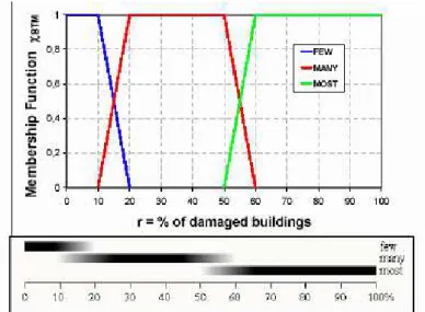
For each scenario the losses in terms of physical damage, referring to the 5 levels of the EMS-98 scale, casualties and repair cost were determined and compared to each other.
In this way the owners of the building stock have an overview of the risk levels due to different scenarios and so they can to establish which is the acceptable risk level and to implement mitigation interventions based on it.
4
Chapter
1
1. Seismic vulnerability of existing buildings
1.1. General aspects
The seismic vulnerability of a building is the propensity to suffer a certain damage level under an earthquake of a given intensity. Thus, the vulnerability assessment is a fundamental step in seismic risk analyses and in the damage scenario for earthquakes of a certain intensity level.
When an earthquake occurs, the physical damage of structural and non-structural elements, the casualties and injuries, the loss of contents and the indirect economic losses due from the business interruption, not depend only from the vulnerability of the buildings, but also from the level of
seismic hazard of the site (maximum expected intensity) and from the exposure (number of people
that live or work in the building, economic values of the construction and of its content, the type of activity performed within the building).
Vulnerability, hazard and exposure are the components of the seismic risk and they have to be assessed and merged together when a scenario risk analysis have to be developed.
Several methods can be used to assess the seismic vulnerability (please see chapter 2), so empirical, analytical or hybrid procedure can be performed. The use of a specific method often depends on the scale of the loss assessment; for a single building, analytical methods are suggested, while in the case of a large-scale with a great number of buildings simultaneously assessed, also empirical or hybrid methods are useful.
The vulnerability of existing structures is a very important issue in Italy, because of the very high number of ancient historical centres, mainly made of unreinforced masonry buildings (URM), and a lot of reinforced concrete structures (RC), built up mainly in the period between the 50’s and the 90’s. About the 40% of the RC buildings was designed according to the law n.64/1974, that introduced basic seismic provisions, so they have low earthquake resistant criteria if the building was built within a zone declared as seismic (not likely because most of the Italian territory was declared as seismic prone area only after 1983).
Thus, the most part of RC buildings ca be considered as PRE Code buildings, that is the lack of earthquake resistance criteria, because or they were designed previously the 1974 (the 60%) or they were designed after the 1974 (the 40%) but they weren’t within a seismically zone.
It worth noting that also the PRE 1974 buildings could have been built within a zone declared as seismically dangerous, thus equivalent horizontal loads were considered in design, but they only increased the stiffness and resistance of the structure, not the ductility for the lack of adequate details (quantity of longitudinal bars and stirrups in the members).
5
The “Casa Italia Report”, published from the Italian government on June 2017, has identified for each region (tab. 1.1) the number of both RC and masonry buildings with high vulnerability and localized in the cities with the highest seismic hazard (agmax > 0.25). The evaluation has been done
starting from data the 2011 ISTAT census.
Table 1.1. Number of buildings with the highest seismic risk in each region
(font: “Casa Italia Report”, 2017)
Region Masonry buildings
RC buildings built before the 1971
Total 494905 71694
Also, the seismic vulnerability of the Italian built heritage has been shown experimentally from several strong earthquakes occurred since the beginning of the 1900 to nowadays. They have shown the weakness of the Italian built up heritage, causing many casualties, physical damage (fig. 1.1) and economic losses (tab.1.2). The latter includes also indirect losses, tax reliefs and exemptions and in tab. II they have been actualized at the 2014 to be comparable each other (font: Centro Studi
6
Figure 1.1. Earthquakes:1908 Messina (upper-left), 1915 Avezzano (upper-right), 1976 Friuli
(lower-left), Irpinia 1980 (lower-right).
Table 1.2. Main destructive events in Italy from 1900 to nowadays
Major Earthquake
in Italy
Date Mw MCS Casualties Economic losses [Bln €]
Stretto di Messina 1908 7.2 XI-XII 120000 -
Avezzano 1915 7.0 XI 33000 - Vulture 1930 6.7 X 1404 - Belice 1968 6.1 X 370 9,2 Friuli 1976 6.4 X 989 18,5 Irpinia 1980 6.9 X-XI 2914 52,0 Umbria-Marche 1997 6.0 IX 11 13,5 Molise 2002 5.7 VIII-IX 30 1,4 L’Aquila 2009 6.3 IX-X 309 13,7
Emilia Romagna 2012 5.9 VIII 27 13,3
7
It is worth noting as the losses are directly linked with the magnitude of the events.
During these earthquakes, mainly URM buildings collapsed or suffered heavy damage. They were usually built with poor materials (fig.1.2), such as rounded stones and inconsistent mortar, and weak connections between walls, walls and floor/roof slabs, thus they exhibit brittle local mechanisms of collapse, such as disaggregation or rocking of the external walls, instead of a global and more ductile response of the whole structure.
Figure 1.2. Collapse of masonry walls made of poor materials (Grisciano (AP), 2016 Centre Italy
earthquake)
Also, RC buildings collapsed or suffered heavy damage during the strongest earthquakes. The main weakness exhibit by RCMF buildings are:
• column-beam joints, where the lack of stirrups and the strong beam-weak column effect have made them very vulnerable to seismic excitement, causing the rupture of the top of the columns (fig.1.3).
Figure 1.3. Rupture due to weak column-beam joint effect (Amatrice, 2016 Centre Italy
8
• soft storeys due to irregularity in the arrangement of masonry infills along the elevation of the building, causing the collapse of many columns at the same storey and the pan-cake effect (fig. 1.4).
a) b)
Figure 1.4. Collapse due to soft storey: (a) Norcia, 2016 Centre Italy earthquake; (b) L’Aquila,
2009 L’Aquila earthquake.
• short columns due to short walls within the frames, knee-beams of the stairs or irregularity in the vertical alignment of storeys, causing the rupture of the free part of the columns (fig. 1.5).
Figure 1.5. Rupture of short columns (Visso, 2016 Centre Italy earthquake)
Further, during the 2012 Emilia Romagna (Magliulo et al, 2014; Belleri et al, 2015) and 2016 Centre Italy earthquakes many industrial pre-cast buildings collapsed (fig.1.6) because of the lack of connections between columns and beams or/and beams and rooftops.
9
Figure 1.6. Partial collapse of a pre-cast RC industrial building (Norcia, 2016 Centre Italy
earthquake)
After the 2002 Molise earthquake, when a school building collapsed killing many children and their teacher. many things changed in Italy with regard to the seismic design of structures and the classification of the seismic prone areas.
A new hazard map for Italy was developed in 2004 and updated over time (Stucchi et al, 2011) by means a probabilistic seismic hazard analysis (PSHA), identifying a 5x5 Km grid with values of the hazard parameters PGA, F0 and Tc for each grid-point. Thus, for each point of the map the
probability to exceed a certain intensity level in a given reference period can be estimated (fig. 1.7).
Figure 1.7. Italy seismic map for a probability of exceedance of 10% in 50 years.
Then the O.P.C.M. n. 3519 dated 2006/04/28 assigned to each city one of the four seismic zones provided:
10 Zone A - high seismicity: ag,max > 0.25 g.
Zone B - medium seismicity: agmax ranged between 0.15g and 0.25 g.
Zone C - moderate seismicity: agmax ranged between 0.05g and 0.15 g.
Zone D - low seismicity; agmax < 0.05 g.
The performance based seismic design approach (PBSDA) (Priestely, 1997, Sullivan et al. 2003) was adopted in the last Italian seismic Code (Norme tecniche per le costruzioni – NTC 2008), adopting the same four performance levels (or limit states) of Eurocode 8 (fig.1.8). The Capacity Design was introduced too, providing the strong column-weak beam behaviour and that the brittle shear failure occurs later the ductile flexural failure in each structural member.
Figure 1.8. Performance levels in PBSDA
Further provisions for the seismic vulnerability assessment of existing buildings were introduced, regarding the knowledge level (KL) to reach and the confidence factor (CF) to use in order to take into account the epistemic uncertainties in constructive details and mechanical properties of materials. Nonlinear static and dynamic analysis procedures were also indicated as the main tools for the evaluation of the seismic response of structures.
11
1.2. Seismic response of RCMF structures
RC structures in which the load-bearing capacity is due by columns, beams and slabs, rigidly linked each other, are called moment frame structures (RCMF, fig. 1.9). They are widespread in Italy, while shear walls RC structures, also known as “dual system”, are very common in earthquake-prone areas but not in Italy.
Figure 1.9. Members of a RCMF structure
The Italian RCMF buildings in the most part was designed in absence of a modern seismic Codes, that require to apply the hierarchy of resistance, until to 2003. The lack of adequate constructive details in the structural members is the main reason of the low ductility offered from these types of structures (fig. 1.10 – b).
Figure 1.10. Ductile (a) and brittle (b)behaviour
Until about the ‘80s RCMF were usually conceived as composed by parallel plane frames, with high beams only in one direction, while in the other direction often only slabs made of RC joists and hollow bricks were arranged. Thus, these structures were able to bear only vertical loads and exhibited a not good response during earthquakes.
12
Subsequently the parallel frames were integrated with load-bearing elements also in the other direction, so a better resistant scheme against seismic action was formed.
However, in both cases the capacity design procedure wasn’t provided in the Codes, thus usually in the buildings we can find weak columns - strong beams ratios and the lack of adequate constructive details to guarantee ductility in the members.
Only recently, after the 2003, the capacity design procedure was introduced and the seismic behaviour of RCMF improved very much.
Thus, there are several subtypes of existing RCMF buildings: • Non-ductile RC frames with/without infill walls.
• Non-ductile RC frames with reinforced infill walls. • Ductile RC frames with/without infill walls.
The masonry infills play an important role in the seismic response of RC framed buildings as described in the final part of this chapter.
The expected seismic response of RCMF structures can be well associated with the age of the buildings, according to the aspects below exposed.
1. Regulations
Generally, in all over the world Code requirements related to design and detailing of RC frame buildings in seismic zones were significantly changed in the early 1970s. Earlier codes focused on the strength requirements—that is, on providing adequate strength in structural members to resist the lateral seismic forces. However, based on research evidence and lessons learned from earthquakes in the early 1970s, code requirements have become more focused on the proportioning and detailing of beams, columns, and joints with the objective to achieve a certain amount of ductility in addition to the required strength.
Ductility is one of the key features required for desirable seismic behaviour of building structures and it needed of adequate constructive details.
The principles and rules of seismic detailing of reinforced concrete structures have been emerging over time and are mainly reflected in seismic provisions of building codes.
In Italy several Codes that regulated the design of RC structures with different levels of earthquake resistance provisions, have succeeded over time. The main Codes are:
• Royal Decree n. 193 dated 18th April 1909 “Norme tecniche ed igieniche obbligatorie per le
riparazioni ricostruzioni e nuove costruzioni degli edifici pubblici e privati nei luoghi colpiti dal terremoto del 28 dicembre 1908 e da altri precedenti elencati nel R.D. 15 aprile 1909 e ne designa i Comuni.”
13
• Royal Decree n. 431 dated 13th March 1927 “Norme tecniche e igieniche di edilizia per le
località colpite da terremoti”.
• Royal Decree n. 2105 dated 22th November 1937 “Norme tecniche ed igieniche per le
riparazioni, ricostruzioni e nuove costruzioni degli edifici pubblici e privati nei comuni o frazioni di comune dichiarati zone sismiche.”
• Royal Decree n. 2229 dated 16th November 1939 “Norme per la esecuzione delle opere in
conglomerato cementizio semplice od armato”,
• Law n. 1684 dated 25th November 1962 “Provvedimenti per l'edilizia, con particolari
prescrizioni per le zone sismiche”.
• Law n. 1086 dated 5th November 1971“Norme per la disciplina delle opere di conglomerato
cementizio armato, normale e precompresso, ed a struttura metallica”.
• Law n. 64 dated 2th February 1974 "Provvedimenti per le costruzioni con particolari
prescrizioni per le zone sismiche".
• Ministerial Decree dated 3th March 1975 “Approvazione delle Norme tecniche per le
costruzioni in zone sismiche”.
• Ministerial Decree dated 12th February 1982 “Criteri generali per la verifica della sicurezza
delle costruzioni e dei carichi e sovraccarichi”.
• Ministerial Decree dated 19th June 1984 “Norme tecniche relative alle costruzioni sismiche”. • Ministerial Decree dated 24th Jenuary 1986 “Norme tecniche relative alle costruzioni
antisismiche”.
• Ministerial Decree n. 285 dated 20th November 1987 “Norme tecniche per la progettazione,
esecuzione e collaudo degli edifici in muratura e per il loro consolidamento”.
• Ministerial Decree dated 14th February 1992 “Norme tecniche per le opere in c.a. normale e
precompresso e per le strutture metalliche”.
• Ministerial Decree dated 9th Jenuary 1996 “Norme tecniche per il calcolo, l’esecuzione ed il
collaudo delle strutture in c.a. normale e precompresso e per le strutture metalliche”.
• Ministerial Decree dated 16th Jenuary 1996 “Norme tecniche per le costruzioni in zone
sismiche”.
• Ministerial Decree dated 16th Jenuary 1996 “Norme tecniche relative ai criteri generali di
verifica di sicurezza delle costruzioni e dei carichi e sovraccarichi”.
• Ordinance of the Council of Ministers n. 3274 dated 20th March 2003 “Primi elementi in
materia di criteri generali per la classificazione sismica del territorio nazionale e normative tecniche per le costruzioni in zona sismica”.
• Ordinance of the President of the Council of Ministers n.3431 dated 3th May 2005 “Ulteriori
14
materia di criteri generali per la classificazione sismica del territorio nazionale e di normative tecniche per le costruzioni in zona sismica»
• Ministerial Decree dated 14th January 2008 “Norme Tecniche per le Costruzioni”.
Also, technical manuals were employed by engineers, such as those known as “Santarella” and
“Pagano”.
These regulations essentially prescribed the minimum resistance of concrete and steel, the maximum admissible values of tension within the cross sections, sometimes the minimum geometrical dimensions of elements and the minimum quantitative of longitudinal rebars and stirrups, the minimum anchor length, the formulation to calculate the bending moment in the members and the values to adopt for dead and live loads.
The 1974 is an important year because, after many years, new provisions were provided for buildings in seismic prone areas.
In the PRE 1974 period the main used design code was the Royal Decree n. 2239 dated 1939. It provided extremely poor rules concerning both design and construction activities, particularly with regard to reinforcement details. No rules were given for design actions and structural details, whereas the concrete was classified by means of the average cubic resistance (Rcm) at 28 days of
ageing. Rcm had to be at least three times the resistance value adopted in the calculations and
contained in the range 120–180 kg/cm2.
Steel, generally in smooth bars, was characterized by nominal allowable strength values variable in 1400 – 2400 kg/cm2 range, according to the adopted type. Ribbed bars appeared for the first time
in 1957 and the most used were the “TOR” and the “Twisteel” types. These rebars reached the
yielding strength of 6000 kg/cm2 but they had to be used with concrete with cubic resistance of 225
- 250kg/cm2 at least.
Another important aspect regulated from the Codes is the seismic classification of the Italian territory. It started after the Messina earthquake and it was updated every time a new strong earthquake occurred, by adding the cities hit to the seismic map. Fig. 1.11 show the classification at the 1909, 1935, 1975, 1984, 2003, 2015.
15
a) b)
16
e) f)
Figure 1.11. Seismic classification of Italy: 1909 (a), 1935 (b), 1975 (c),
1984 (d), 2003 (e), 2015 (f)
It is wort noting as after 1984 the classification spread very much and involved the most part of the territory.
Thus, for the seismic areas the regulations determined the level of hazard to assume (seismic categories) and the entity of the seismic forces to apply at the storey as equivalent horizontal loads (% of the storey weight depending on the seismic category of the zone).
2. Mechanical properties of the materials
Further, the type of steel used for reinforcement and the mechanical properties of concrete depending on the reference period. In fact, the industrial production improved over time and so the quality of materials and the constructive techniques.
Until to ’70 usually smooth steel bars were used (tab. 1.3), anchored by bending their extremities according to a hook shape, while in the subsequent period ribbed steel bars (tab. 1.4) were largely used.
Table 1.3. Type of smooth steel bars
Aq 42 Aq 50 Aq 60 Feb 22K Feb 32K
Yield strength [N/mm2] > 230 > 270 310 220 315
Ultimate strength [N/mm2] 420 500 600 335 490
17
Table 1.4. Type of ribbed steel bars Feb 38K Feb 44K
Yield strength [N/mm2] 375 430
Ultimate strength [N/mm2] 450 540
Minimum elongation [%] 14 12
Thus, is possible to individuate 3 main reference periods for Italian RC structures:
• PRE 1974, in which most of buildings are designed only for vertical static loads (PRE Code buildings) and smooth bars were used as reinforcement.
• POST 1974, in which most of buildings in seismic area keep in account seismic loads and they have a low level of earthquake resistant design (Low Code buildings). Ribbed rebars were used as reinforcement.
• POST 2003, in which buildings are designed according to the Capacity Design procedure and they account for the expected intensity level provided from the last hazard map (High Code buildings).
The buildings belonging to each period differ for the quality of materials employed, for the values of live loads and for constructive details such as:
• Minimum cross section of members. • Quantity of longitudinal bars. • Quantity of stirrups.
• Anchor length.
The PRE and POST 1974 non-ductile RCMF buildings, although sometimes designed to resist to lateral forces, did not incorporate modern ductile seismic detailing provisions. As a result, the main seismic deficiencies include:
• Inadequate column detailing. The two main detailing problems include inadequate column lap splices for main flexural reinforcement and a lack of adequate transverse reinforcement (ties) within the column. As an example, column lap splices were typically placed just above the floor level in the zone of high stresses. In addition, the column lap splices were generally too short, often in the order of 30-bar diameters, or less, and were typically not confined with closely spaced column ties (as required by modern codes).
• Lack of strong column/weak beam design approach. A capacity design approach was not followed in the design of the beam flexural reinforcement, as the beams were generally designed for the code level forces. The effects of post-yield behaviour were not considered, thus
18
increasing the chances for undesirable shear failure in either the beams or columns. Shear failure is rather brittle and sudden, and should be avoided in reinforced concrete structures located in seismic zones.
• Inadequate anchorage of beam reinforcement. The top reinforcing bars in beams were often terminated in the column or just away from the column face, whereas the bottom bars were typically discontinued at the face of the supporting column or provided with only a short lap-splice cantered on the column.
• Excessive tie-spacing. Spacing of ties in beams and columns was excessively large by today’s standards. Column ties often consisted of a single hoop with 90-degree hooks spaced at 20 to 30 cm on the whole length of the column. Today’s ties generally require 135-degree hooks to ensure adequate confinement. Beam ties, often sized only for gravity shear loads, were spaced closely near the column face but were widely spaced or even discontinued in the mid-span region of the beam.
• Inadequate beam/column joint ties. The lack of ties in the beam/column joint created a weak zone and likely failure mechanism within the joint.
Further, the seismic performance of RC buildings could be poor because of the presence of some deficiencies that for several reasons affect the construction:
• Alteration of the member sizes during the construction phase from specifications in the design drawings
• Noncompliance of the detailing work with the design drawings.
• Inferior quality of building materials and improper concrete-mix design.
• Modifications in the structural system performed by adding/removing components without engineering input.
• Reduction in the amount of steel reinforcement as compared to the design specifications. • Poor construction practice.
The seismic response of RCMF structures designed according to Old Codes has been investigated from several authors employing different procedures:
• Empirical analysis of damaged buildings after earthquakes (Manfredi et al. 2010, Ricci et al.
2010, Manfredi et al. 2014).
• Numerical investigations through nonlinear analysis (Fardis 1997, Masi et al. 2003,
Magliulo et al. 2007, Makarios et al. 2012, Mohammad et al. 2016).
• Experimental investigations in laboratory on single RC members (columns, beams, beam-column joints) (Hakuto et al. 2000, Braga et al. 2000, Di Ludovico et al. 2014) and on
19
full/partial scale of plane or spatial frames (shake table or static tests) (Pinto et al. 1999,
Calvi et al. 2002, Albanesi et al. 2008).
These investigations highlighted several important aspects, summarized in the following part. RCMF buildings exhibit, under strong earthquakes, plastic deformations lumped on the extremity of beams and columns, also involving the beam-column joints on the base of the quantity of longitudinal bars and stirrups within structural elements converging in the joint. In fact, a lot of longitudinal bars and the low quantity of stirrups can determine the occurrence of a brittle shear collapse before the ductile flexural collapse.
The strong beams - weak columns effect (Park and Paulay, 1975) is due to the low quantity of longitudinal rebars in the columns.
The most favourable mechanisms of collapse forbid the brittle shear rupture of bam-column joints and of the other elements, while involving the plasticization of the largest number of members, such as the beams of the all levels and the columns at the ground floor (strong column-weak beam behaviour). The occurrence of this ductile mechanism requires to design the structure according to the Capacity Design principles (EC 8).
Generally, the Capacity Design principles and the regularity in plan and in elevation are not considered in the design of existing RC buildings. Thus, it is more likely the occurrence of a soft storey mechanism (fig. 1.12 – a), involving mainly the columns at the same floor, instead of ductile mechanism (fig. 1.12 - b).
Figure 1.12. Soft-storey (a) and ductile (b) mechanisms of collapse.
In many applications, architectural considerations result in a taller first story, which causes a soft-story formation due to drastic change in the stiffness between adjacent stories. The presence of a soft story results in a localized excessive drift that causes heavy damage or collapse of the story during a severe earthquake. Another typical case of soft story arises when the first floor is left open (that is, no infills) to serve a commercial function (stores) or as a parking garage, while upper floors are infilled with unreinforced masonry walls.
20
A relatively rare case results when the strength of the two adjacent stories is significantly different (weak story) leading to localized deformations similar to the soft-story mechanism. Thus, the collapse mechanism could involve only a floor (the weakest) with the formation of plastic hinge to the ends of the columns. This is a brittle collapse mechanism because of both the low number of dissipative elements involved and the limited ductility capacity of the columns subjected to high axial loads (rigid-brittle behaviour).
Other typical non- ductile failure mechanisms are:
• Shear failure and concrete crushing failure in concrete columns. Brittle shear mechanisms are caused by the low quantity of stirrups in columns, particularly in the end zones and in the column-beam joints (fig. 1.13).
These are the most undesirable nonductile modes of failure and they can lead to the loss of gravity load-bearing capacity in the columns and potentially a total building collapse.
Figure 1.13. Shear failure and concrete crushing failure in concrete columns
• Short-column effects. The short or captive column failure (fig. 1.14) occurs due to partial restraining of the columns that are, in turn, subjected to high shear stresses and fail in shear if unable to resist these stresses.
21
Another important aspect of the vulnerability of RC buildings is the medium compression stress in columns. In fact, it influences the ductile capacity of columns and so the behaviour factor of the whole structure. High levels of compression lead to higher rotational stiffness and lower ductility. Further the compression level in columns is strongly correlated with other aspects, such as the structural masses and the dimensions of columns, thus with the seismic forces and the resistance of the columns that directly influence the vulnerability.
In the SAVE project (Dolce et al. 2005-a), the correlation between the compression level in columns of the ground floor and the vulnerability was investigated analysing several buildings by means the VC method (Dolce et al. 2005-b) and the results are shown in fig. 1.15 (on the X axis the medium compressive stress in columns, on the Y axis the structural capacity in terms of PGA).
Figure 1.15. Correlation between medium compression in columns and collapse capacity
It worth noting as the maximum medium values founded in each building assume values higher than 4 MPa, meaning that the local values in columns could be very high with respect the compressive resistance of the concrete used in the ’60 and ’70, usually lower than 20 MPa
Further, the capacity assumes high values for medium compressive stresses lower than 1 MPa, while the capacity decreases for higher values of the stress in columns.
Structural irregularities
The simplicity, symmetry and regularity in terms of both resistance and stiffness distributions are important factors governing seismic response of RC structures.
In fact, frame structures that have performed remarkably well during earthquakes have had regularity and symmetry about two orthogonal axes in plan and regularity in elevation. If a building
22
is symmetric about orthogonal axes in plan, then it does not twist during the action of earthquake and the seismic demand doesn’t increase on columns.
Further if the building has rigid floor diaphragms, then all columns are subjected to the same inter-storey drifts.
Whereas, those that have not performed well during earthquakes had symmetric and non-regular plans and/or vertical irnon-regularities in the form of weak and/or soft stories, buildings undergone major structural alterations-addition of floors, removal of load resisting members, and structures constructed on weak, unstable, or different foundation soil systems.
Shape irregularity (fig. 1.16), which often results in structural irregularity, determines the concentration of stresses and so of the damage in specific parts or storeys of a building, and may even cause collapse.
Figure 1.16. Unfavourable and favourable planar shapes (After Penelis and Kappos 1997)
Typically, stiffness and strength distributions of Old Code buildings are not symmetric in both principal directions in plan because structures were calculated without taking into account the three-dimensional effects (only plane effects). Further stiffness and strength usually are not regular even along the height of the building (fig. 1.17).
23
The presence of columns having a constant quantitative of longitudinal bars along the height, determines a structural irregularity in terms of storey resistances, being the ratio between the maximum resistant shear and the external shear forces significantly variable between storeys. Especially for those building designed for gravity loads only, frames are usually present in one direction, generally the longer one (longitudinal), identifying a strong direction, whilst in the orthogonal direction the frames are present on the external sides only in order to withstand the weight of external walls.
Due to this characteristic, the transverse direction can be considered the weak direction.
Further the gravity load design procedure determines modest dimensions of the columns, low quantitative of steel reinforcement and an irregular stiffness distribution in elevation.
These lead to a lower lateral stiffness and in a consistent difference between the stiffness of the two main directions, being the transverse direction more deformable then the longitudinal one. Thus, two similar buildings designed according to different Codes but with the same masses, have different fundamental vibration period and this condition should to be valid also when the buildings reach the non-linear range.
In fact, in Old Code buildings the modest dimensions of the cross sections, the low percentage of steel reinforcement, the different mechanical characteristics of the materials determine a lower resistance and a higher deformability in the post elastic range.
The stairs, usually arranged along the transverse direction, have a stiffening effect that decrease with the height of the building. For low rise buildings (2 or floors) the fundamental vibration period for the transverse direction can be lower than those for the longitudinal direction.
Further, the stairs, which are usually placed in an eccentric position, often emphasize the irregular stiffness distribution provided by position in plan of the infill panels. These features may result in global torsional effects and brittle collapse.
The longitudinal direction, having parallel plane frames, is characterized from an increasing stiffness with the surface of the plan, because of increase also the number of both spans and parallel frames. The same is for the transverse direction, even if the stiffness increase less than the other direction because only the number of the spans in the perimetrical frames contributes to the increment.
Then the seismic behaviour of RCMF structures can be strongly affected by the presence of
masonry infill walls especially in those cases in which the external walls are made with “strong”
infill panels. Their influence was assessed from several authors (Panagiotakos et al. 1995, Dolsek
et al. 2008, Asteris 2012, Sattar et al. 2016) and they can lead to either an increase or a decrease in
seismic resources.
If the infill walls are arranged uniformly both in plant and elevation, and the building is not too tall, they increase the lateral stiffness and resistance of the whole structure and can both reduce the inter-storey drift demand and rise the overall resistance to horizontal actions.
24
Instead, an uneven distribution may have negative effects because of they cause irregularity of stiffness and strength, fostering the occurrence of unexpected behaviours and possibly increasing the seismic demand against sensitive zones where concentrations of stress and large ductility demands might prematurely cause collapse due to soft storey mechanism (Dolsek et al. 2001,
Verderame et al. 2011).
Further, the sudden reduction of storey stiffness due to the damage of the infills during an earthquake can lead to the formation of an unexpected soft storey mechanism, which, due to the interaction with the joint damage, can occur not necessarily at the first floor and independently by the regular or irregular distribution of the infills along the elevation.
The infills can generate also dangerous local effects on the RC frame as:
• The plasticization of the extremities of columns for the presence of a considerable tension stresses due to infill (fig. 1.18).
• The local and brittle rupture of columns for the presence of irregular openings in the walls.
Figure 1.18. Local stresses on columns due to infill
Further, masonry infills could suffer heavy damage detaching from the frame (fig. 1.19) or rocking out of the plane (Furtado et al. 2015 a-b) and so becoming themselves dangerous for people.
25
Figure 1.19. Out of plane (left) and in-plane failure (right) of masonry infills
Given the high stiffness of the masonry infills, it is important to consider them also in structural modelling, because the elastic period of the building modelled without infills is very different to the one obtained experimentally by means in situ measurement of environmental vibrations. However, these vibrations have a very limited amplitude and so the building could be stiffer than when an earthquake occurs causing damage on the building. For these reasons the cracked stiffness of both concrete and masonry could be adopted when numerical simulations are performed.
26
References chapter 1
• Presidenza del Consiglio dei Ministri, Struttura di Missione Casa Italia. Rapporto sulla Promozione della sicurezza dai Rischi naturali del Patrimonio abitativo, june 2017.
• Belleri A., Brunesi E., Nascimbene R., Pagani M., and Riva P., “Seismic Performance of Precast Industrial Facilities Following Major Earthquakes in the Italian Territory,” J. Perform. Constr. Facil., vol. 29, no. 5, p. 4014135, Oct. 2015.
• Magliulo G., Ercolino M., Petrone C., Coppola O., and Manfredi G., “The Emilia Earthquake: Seismic Performance of Precast Reinforced Concrete Buildings,” Earthq. Spectra, vol. 30, no. 2, pp. 891–912, May 2014.
• Stucchi et al., Seismic Hazard Assessment (2003–2009) for the Italian Building Code, Bulletin of the Seismological Society of America, Vol. 101, No. 4, pp. 1885–1911, August 2011
• Priestley, M. J. N. (1997). Displacement-Based seismic assessment of reinforced concrete buildings. Journal of Earthquake Engineering, 1, 157-192.
• Sullivan T.J. The limitations and performances of different displacement based design
methods.Journal of Earthquake Engineering 7(sup001):201-241. 2003.
• Ministro dei Lavori Pubblici e dei Trasporti, “DM 14/01/2008 – NTC - Norme tecniche per le costruzioni (in Italian),” Suppl. Ordin. Gazz. Uff. n. 29, 2008.
• “Ordinanza del Presidente del Consiglio dei Ministri (OPCM). General criteria for the seismic classification of the national territory and technical standards for constructing in seismic zones. Ordinance no. 3274, G.U. n. 72 del 8–5-2003 (in Italian).” 2003.
• Santarella, L. (1968), "Il cemento armato – Le applicazioni alle costruzioni civili ed industriali", II volume, Edizione Hoepli.
• Pagano, M. (1968) Teoria degli edifici – Edifici in cemento armato, Edizione Liguori, Napoli (in Italian).
27
• Regio Decreto 16/11/1939 n. 2229, "Norme per la esecuzione delle opere in conglomerato cementizio semplice ed armato".
• Legge 5/11/1971 n. 1086, "Norme per la disciplina delle opere in conglomerato cementizio armato, normale e precompresso ed a struttura metallica".
• Manfredi G. et al. Preliminary analysis of a soft-storey mechanism after the 2009 L’Aquila earthquake. Earthquake Engng Struct. Dyn. (2010).
• Ricci P., De Luca F., Verderame G.M. 6th April 2009 L’Aquila earthquake, Italy — Reinforced concrete building performance. Bulletin of Earthquake Engineering 2010.
• Manfredi G. et al. 2012 Emilia earthquake, Italy: reinforced concrete buildings response. Bulletin of Earthquake Engineering October 2014, Volume 12, Issue 5, pp 2275–2298.
• Fardis M.N. Experimental and numerical investigations on the seismic response of RC infilled frames and recommendations for code provisions. Report ECOEST-PREC8 No 6. Prenormative research in support of Eurocode 8, 1997.
• Masi A. (2003). Seismic vulnerability assessment of gravity load designed R/C frames, Bulletin of Earthquake Engineering, Vol. 1, N. 3, pp. 371-395.
• Magliulo G. et al. Seismic response of three-dimensional r/c multi-storey frame building under uni- and bi-directional input ground motion. Earthquake Engng Struct. Dyn. 2007; 36:1641– 1657.
• Makarios et al. Numerical Investigation of Seismic Behavior of Spatial Asymmetric Multi- Storey Reinforced Concrete Buildings with Masonry Infill Walls. The Open Construction and Building Technology Journal, 2012, 6, (Suppl 1-M8) 113-125.
• Mohammad et al. Seismic performance of older R/C frame structures accounting for infills-induced shear failure of columns. Engineering Structures, 122 (2016), 1-13.
• Hakuto, S, Park, R and Tanaka, H, Seismic Load Tests on Interior and Exterior Beam- Column Joints with Substandard Reinforcing Details, ACI Structural Journal, 97(1), 2000, 11-25
28
• Braga et al. R/C Existing Structures with Smooth Reinforcing Bars: Experimental Behaviour of Beam-Column Joints Subject to Cyclic Lateral Loads. The Open Construction and Building Technology Journal 3(1):52-67. May 2009.
• Di Ludovico M. et al. Cyclic Behavior of Nonconforming Full-Scale RC Columns. Journal of Structural Engineering Volume 140 Issue 5 - May 2014.
• Pinto A, Verzeletti G, Molina J, Varum H, Pinho R, Coelho E (1999) Pseudo-dynamic tests on non-seismic resisting RC frames (bare and selective retrofit frames). Joint Research Centre, Ispra.
• Calvi G.M., Magenes G., Pampanin S., Experimental Test on a Three Storey Reinforced Concrete Frame Designed for Gravity Only, 12th European Conference on Earthquake Engineering, paper n.727, London 2002.
• Albanesi T., Biondi S., Candigliota E., Le Maoult, A. and Nuti, C. (2008), “Seismic full-scale test son a 3D infilled RC frame”, Proceedings of 14th WCEE, CD-ROM, Beijing, China. • Park P., Paulay T., 1975. Reinforced Concrete Structures, Wiley. CEN (Comité Européen de
Normalisation), “Eurocode 8: Design of structures for earthquake resistance – Part 1: General rules, seismic actions and rules for buildings (EN 1998-1)” 2004.
• Dolce M., Martinelli A. Inventario e vulnerabilità degli edifici pubblici e strategici dell’Italia centro-meridionale, Vol. II - Analisi di vulnerabilità e rischio sismico, INGV/GNDT, L’Aquila, 2005.
• Dolce M., Moroni C., 2005. La valutazione della vulnerabilità e del rischio sismico degli edifici pubblici mediante le procedure VC e VM. Progetto SAVE, Atti di Dipartimento N. 4/2005
• Penelis G.G., Kappos A.J., Earthquake Resistant concrete structures, E&F Spon, London, 1997.
• Panagiotakos T.B. and Fardis M.N., (1996), “Seismic response of infilled RC frames structures”, 11th World Conference on Earthquake Engineering, paper 225.
29
• Dolsek M. and Fajfar P., (2008), “The effect of masonry infills on the seismic response of a four storey reinforced concrete frame - A deterministic assessment”, Engineering Structures, 30(11), 1991-2001.
• Asteris P., & Cotsovos D. (2012). Numerical investigation of the effect of infill walls on the structural response of RC frames. The Open Construction and Building Technology Journal, 6 (Suppl 1-M11), 164-181.
• Sattar S., Liel A.B. (2016) Seismic Performance of Nonductile Reinforced Concrete Frames with Masonry Infill Walls—II: Collapse Assessment. Earthquake Spectra: May 2016, Vol. 32, No. 2, pp. 819-842.
• Dolšek M., Fajfar P., (2001). “Soft storey effects in uniformly infilled reinforced concrete frames”, Journal of Earthquake Engineering, 5(1), 1-12.
• Verderame G.M., De Luca F., Ricci P. and Manfredi G., (2011), “Preliminary analysis of soft-storey mechanism after the 2009 L'Aquila earthquake”, Earthquake Engineering and Structural Dynamics, 40, 925-944.
• Furtado et al. 2015. Influence of the in Plane and Out-of-Plane Masonry Infill Walls’ Procedia Engineering. Interaction in the Structural Response of RC Buildings. Volume 114, 2015, 722-729.
• Furtado et al. 2015. Experimental Characterization of the In-plane and Out-of-Plane Behaviour of Infill Masonry Walls. Volume 114, 2015, 862-869.
30
Chapter
2
2. Methods for seismic vulnerability assessment of buildings
The seismic vulnerability of a building is the susceptibility to suffer damage due an earthquake of a certain intensity. From this definition born the need to establish a correlation able to provide the expected damage level for each intensity level, identifying appropriate damage and intensity measure parameters.
Several possibilities exist to choose the parameters and a lot of the methods, different in purposes and procedures, are available to explicit this relationship. Further, the latter can be obtained from both a deterministic or probabilistic approach.
The criteria to classify the methods for vulnerability assessment are shown in tab. 2.1.
Table 2.1. Seismic vulnerability assessment methods
Metodology classification Types of techniques Description ON THE BASE OF THE TYPE OF RESULT
Direct
Indirect
Conventional
They provide the result as a forecast of the estimated damage.
They first determine a vulnerability index (V) and then they use a relationship intensity-damage that is function also of V.
They are heuristic. According to several criteria they allow to assign an index V, they don’t associate a forecast of the damage and they are useful to compare building located in area with different seismic hazard level.
ON THE VASE OF THE TYPE OF MEASURE
Quantitative
Qualitative
They provide the result (damage) in a numerical form (probabilistic or deterministic).
They sue descriptions in terms of qualitative levels (low, medium, high).
ON THE BASE OF THE TYPE OF ELABORATION
Statistical
Modelling
They research the result by means the statistical elaboration of the observed data, in particular those of damage and vulnerability observed after earthquakes. They research the result by means the study of the seismic response.
31 Expertise
Hybrid
They are based on the judgment of experts. They combine more techniques.
ON THE BASE OF THE WAY OF CONCEPTION OF THE STRUCTURAL SYSTEM Typological Semeiotics Mechanistic
They differentiate the seismic behaviour of buildings by assuming typological classes in function of the quality of materials, of the constructive techniques etc. They need of a modest effort and thus they are suitable to be used for large scale assessment.
They consider the buildings as organisms in which the vulnerability (V) can be described through the observation of some behavioral symptoms, that are translated into parameters affecting with different weights the vulnerability. They need of a certain expertise in the data detecting, that can use also for other purposes.
They need to model the seismic response of the buildings as realistic as possible. They are useful to assess a single building or few buildings of the same typology. They can support the other techniques in order both to transfer on single buildings the results for typological classes and to validate the attribution of the vulnerability levels through the behaviour factors.
One of the more complete criteria considers several techniques: direct, indirect and conventional
(Corsanego and Petrini 1994). Direct techniques are subdivided in typological and mechanical,
while the indirect ones are an evolution of the conventional methods. Hybrid techniques merge elements come from two or more techniques above cited.
In direct methods, the correlation is directly found, while in the indirect ones a vulnerability index is first calculated and then the correlation is found.
Direct methods provide an absolute vulnerability, that are vulnerability functions representing the mean damage on the seismic intensity, or probability conditional distributions of the occurrence of a certain damage level given the seismic intensity. The latter represent Damage Probability Matrices – DPMs (fig. 2.1 – a) (Whitman et al. 1974), if a discrete intensity measure is used, or fragility curves (fig. 2.1 – b), if the seismic parameter is continuous.
Fragility curves are cumulative probability functions that can obtained through analytical or empirical procedure.
32
Figure2.1. (left) DPM for damage levels of EMS-98 scale; (right) fragility curves for damage
states
Indirect methods provide a relative vulnerability, that is vulnerability indices obtained empirically or experimentally. After that a relation between indices and damage expected for the intensity levels can be found.
Direct typological methods usually are based on real experiment of strong earthquakes, whose data
on damage are processed through statistical regressions in order to obtain DPMs for a limited number of building categories. Therefore, they are empirical methods and their application requires a census of the main qualitative parameters that allow to classify the buildings according to defaults types, to each of them can be associated a BTM (Building Typology Matrix).
The BTMs, like the DPMs, directly provides the conditional probability (P) to reach a certain damage level (D) once individuated the typological class (T) and for a given intensity level (I):
P [d | T, I]
In Italy, the first empirical DMPs were developed in the 1980 after the Irpinia earthquake (Braga
et al. 1982).
As the available data are often limited and do not concern all the building typologies and all the intensities that it would be necessary to represent in a model, the probabilistic processing of the observed data, at the root of observational methods, is supported or completely replaced by other approaches such as expert judgement (ATC-13 1987), neural network system (Dong et al. 1988) or Fuzzy Set Theory (Sanchez-Silva et al. 2001).
33
Recently, methods based on the EMS-98 macroseismic scale (Grunthal et al. 1998) are widely used for rapid vulnerability assessment on large scales (i.e. urban, regional or national scale).
Direct typological methods provide a good robustness in statistical terms, but on the other side they can’t provide plausible results for the single building.
Direct mechanical techniques are based on numerical analyses with different complexity,
performed on a single building or on a category of buildings.
The application of mechanical techniques requires a cataloguing of constructions, which includes their mechanical characteristics, and identifying the structural type of each construction. The results of the evaluations are then processed by means of statistical procedures whose result consists in the determination of the level of damage expected for a single construction or for a single category. Between the analytical methods, those based on the Capacity Spectrum procedure (Freeman 1998,
Fajfar 1996) are widely used in risk assessment framework such as the HAZUS (FEMA 1999) and
Risk UE (Milutinovic et al. 2003) methods.
Indirect conventional techniques are based on virtual experiments of experts (expert judgment)
with statistical processing of the data. The result is a conventional score (vulnerability index) attributed to a construction or a category by assessing the factors which govern the seismic response. The application of these techniques requires a field survey, sometime performed in a rapid or simplified way, of typological, structural, geometric, constructive characteristics. Some of these methods are the Rapid Visual Screen - RVS method provided by (ATC-21 1988) and the 2nd level
GNDT method provided in the first form by (Benedetti and Petrini 1989).
The hybrid techniques combine the previous techniques in order to obtain the methods more
complete and reliable. In fact, it can happen that there is a lack of data relative to the damage observed for certain levels of macroseismic intensity then it is possible to integrate the empirical data with those from non-linear analysis of representative structural models (Kappos et al. 2016). In the same way, data from expert judgment may be supported by more detailed numerical evaluations as in RE.S.I.STO method (Savoia et al. 2013).
Some papers (Calvi et al. 2006, Lumantarna et al. 2014) provide a more depth description of the several methods available for seismic vulnerability assessment of existing RC buildings.
Generally, the choice of the methods depends on the number of buildings to analyse. When a single or few buildings have to be assessed, it should be carried out mechanical models, that take into account the non-linear behaviour of structural elements (i.e. lumped inelastic hinges or spread plasticity models) and numerical analyses (i.e. non-linear static or dynamic analysis). While in the case the assessment of a large amount of buildings is request, numerical models could be too expansive to develop, thus it is preferable to adopt more rapid methods such as the macroseismic ones or those base on the expert judgment.
34
It is particularly interesting to apply the different methods of estimation of seismic vulnerability in order to grasp similarities and weaknesses of each method, taking as reference the detailed analysis performed on nonlinear models that are more reliable.
The development of methods for seismic vulnerability assessment that have a precise validity, providing a reliable estimate on single building rather than an estimate in statistical sense, requires careful verification of the reliability of the results.
This is because the application of these methods was born usually from the need to compare the conditions of risk for different buildings in different sites, thus they can be ordered in a ranking of risk to perform the mitigation policies through the intervention on individual buildings with special features, rather than sets of buildings with common characteristics.
Assessments, therefore, must be reliable not merely in conservative sense, as it is usually required for the methods of analysis for the design and verification of structural safety, but estimating the most likely value of the earthquake resistance and of the action that can determine the limit conditions for the structure
In the following part of the chapter is illustrated a brief description of the several methods available in the literature and in the practice.
2.1. Rapid methods
The use of rapid methods become important when many buildings have to be assessed and the available resources are limited. These methods usually assign a vulnerability class (macroseismic methods) to the buildings on the base of the knowledge of few structural characteristics such as the type of the vertical structure, type of floor slabs etc.
The vulnerability index method is more expansive because accounts for more details, but it is at the same time a rapid method for large scale vulnerability assessment.
Thus, rapid methods allow to compare the vulnerability levels between the buildings belonging to the stock and so to develop a ranking in order to prioritize the risk mitigation interventions. Although the results for the individual building cannot be considered reliable in the strict sense, because they are not obtained from sophisticated analyses that take adequately into account the structural characteristics and materials used (but are much more expensive in terms of time and costs because they require carrying out in situ investigations), for a comparative evaluation can be considered more than enough. In fact, the uncertainties inherent the adopted model are the same for all the buildings, then in a certain sense they cancel and what remains are the differences between buildings.
This is even more valid if a collection of buildings belonging to the same type is analyzed, as in the case of RC school buildings, whose characteristics are common and well defined.