Coherent PON System with High-Sensitivity
Polarization-Independent Receiver and no ADC/DSP
F. Bottoni(1), M. Rannello (1), M. Artiglia(1), M. Presi(1) and E. Ciaramella(1) (1)
Scuola Superiore Sant’Anna, V. G. Moruzzi, 1 – 56124 – Pisa (ITALY) [email protected]
Abstract A 1.25 Gb/s ASK PON system with -51dBm sensitivity (at BER=2∙10-3) is enabled by a polarization-independent coherent receiver that needs no DSP (nor ADC). The system just uses common DFBs and commercial electronic devices and has 52 dB dynamic range.
Introduction
Coherent WDM-PON access networks are promising candidates to achieve seamless upgrade of existing fibre plants, which are based on high-loss power splitters1. Coherent systems can provide for increased power budget and much higher channel density, but these targets must be achieved with low-cost implementation of the receiver2, i.e. without expensive photonic and/or electronic components (e.g. external cavity lasers, ADC's and complex DSP).
We recently proposed a WDM-PON coherent system based on simple and effective ASK phase diversity-receiver3, where a 3x3 symmetric coupler allows coherent detection based on a common DFB as local oscillator (LO), with no special frequency control. We later introduced the extension to polarization-independent receiver (PI-RX), which exploits the 3rd input of the coupler and requires intradyne operation4. These demonstrations however, used offline processing in a Real Time Oscilloscope (RTO) to demodulate the signal. Here we demonstrate for the first time a real-time implementation of the PI-RX, and thus test it in a complete and realistic system experiment. Namely, the PI-RX is realized with commercial devices, without any specific Digital Signal Processing (DSP), thus not requiring expensive ADC's: we rather use commercial high-frequency multipliers, amplifiers and
combiners. Despite the very simple
implementation, we still obtain <-50 dBm sensitivity (at FEC level), which can sustain a
very high loss of the Optical Distribution Network (ODN). This can make it a promising candidate for future PON solutions.
Experimental Results
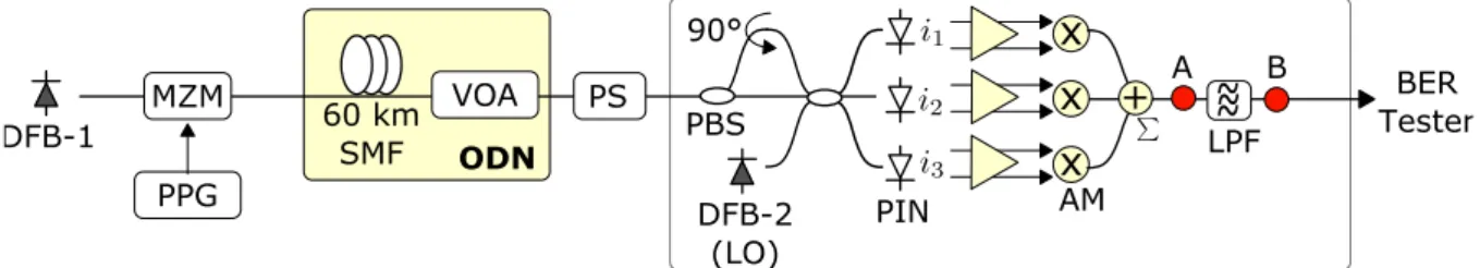
Our experimental setup is shown in fig. 1. Here, for simplicity, the transmitter was made of common DFB (=1540.8 nm, 10 MHz linewidth and -145 dB/Hz RIN) externally modulated by a Mach-Zehnder modulator (MZM), driven at 1.25 Gb/s by a PRBS sequence (231-1 bits long). Since we are focusing on the receiver performance, we use external modulation at the transmitter in order to isolate signal-related impairments: we already demonstrated, although with offline processing, that the RX can work with directly modulated laser (DML) with similar performance5. The ODN is emulated by a 60 km single-mode fibre (SMF, 13 dB loss) a variable optical attenuator (VOA) and a Polarization Scrambler (PS), which simulates the random variations of the signal State of Polarization (SoP).
A key block in our setup is the real-time PI-RX, whose schematics is reported on the right of Fig. 1. At the RX input, the X and Y-polarization components of the signal are separated by a PBS; one of them is rotated by 90° and then they both enter with parallel SoP into a symmetrical 3x3 fused-fibre power coupler4. The LO (-3 dBm) is injected at the 3rd input port of the coupler, with same SoP as the above two. The LO is a common DFB with same specs as the DFB in the TX, whose wavelength is tuned
Fig. 1: Experimental Setup: DFB: Distributed FeedBack Lasers; MZM: Mach-Zehnder Modulator; SMF: Single Mode Fiber; VOA:
Variable Optical Attenuator; ODN: Optical Distribution Network; PS: Polarization Scrambler; PBS: Polarization Beam Splitter; AM: Analogue Multipliers; LPF: low-pass Bessel filter (933 MHz BW); BER: Bit Error Rate Tester. Red dots: measuring points A and B.
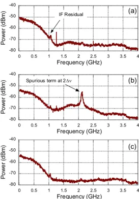
(by thermal control) to work in intradyne regime with 850 MHz (: frequency difference between signal and LO). This is a condition needed to achieve polarization independence (as theoretically demonstrated4). The above can be varied in a 200 MHz range without impairing the overall performance. At the three outputs, each signal is detected by a PIN+TIA photodiode (2 GHz bandwidth), with differential outputs. Once properly amplified by low-noise (5dB noise figure) RF amplifiers, these feed three analogue multipliers (Analog Devices ADL-5391), with 2 GHz operating bandwidth (starting from DC). Since we feed the multipliers with the differential current pairs, the squaring operation is effectively obtained on each photocurrent. The squared signals are finally summed by an electrical power combiner () to yield the recovered signal intensity. The sum signal is then passed through a standard low-pass filter (LPF, 4th order Bessel, with 933 MHz BW), which is present in any NRZ receiver. We report in Fig. 2 the electrical spectra of the recovered signal before and after the LPF. Trace (a) shows the spectrum obtained when the SoP of the input signal is aligned to the LO, which is the typical NRZ spectrum: here we also see a residual tone at frequency (in-band with the signal). This tone is due to a non-ideal behavior of the receiver components (e.g. not exact 120° phase shift within the 3x3 coupler,
slightly different PIN responsivities, non-ideal frequency-response of the multipliers etc.). However, this spurious tone has very low amplitude thus it does not affect significantly the receiver performance. Trace (b) shows the spectrum taken at point A in Fig. 1 when the input signal has a SoP rotated by 45° in respect to the LO, which is the worst-case condition for the RX: as expected4, here a spurious tone at 2 (which has maximum amplitude for this SoP) is observed. This tone has significant amplitude and might be able to impair the system. However, being at high frequency, it is effectively suppressed by the LPF, and a clear signal is indeed obtained at point B in Fig. 1. The corresponding spectrum is in Fig. 2-c. As a side effect, for this input SoP, the clock line (at 1.25 GHz) is strongly reduced, likely due to a kind of jitter which was numerically predicted4: however, this is not a problem for the clock and data recovery circuit.
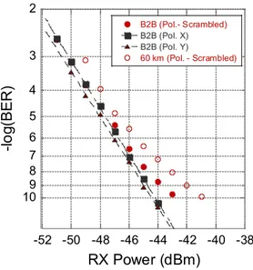
Fig. 3 shows the eye diagrams taken after the LPF Bessel filter, when the signal SoP is exactly aligned to that of the LO and when the SoP of the signal is completely scrambled. By comparing these two eye diagrams, minor differences are observed, namely in case b) the eye diagram shows thicker traces. This has however a very limited impact on the system performance, as we see in Fig. 4, which reports the real-time bit error ratio (BER) values measured by a BER tester.
We then characterize the receiver as a function of the signal input power. In Fig. 4 we report the BER measurements of the RX. First, we show the back-to-back (B2B) measurement of the PI-RX performance when the signal SoP is parallel to the first (black squares) or second (black triangles) axis of the PBS. In both cases, the receiver performs very well. We see that the two polarizations show a slightly different performance, likely due to a slightly different insertion loss of the PBS at its two outputs. We then stress the PI-RX by turning on the polarization scrambler (PS) just in front of it. The scrambler randomly changes (at 6 kHz) the signal SoP so that it uniformly covers the -80 -70 -60 -50 -40 0 0.5 1 1.5 2 2.5 3 3.5 4 P o w e r (d B m ) Frequency (GHz) -80 -70 -60 -50 -40 0 0.5 1 1.5 2 2.5 3 3.5 4 P o w e r (d B m ) Frequency (GHz) -80 -70 -60 -50 -40 0 0.5 1 1.5 2 2.5 3 3.5 4 P o w e r (d B m ) Frequency (GHz) (c) (b) (a) Spurious term at 2 IF Residual
Fig. 2: Electrical signal spectra; a): taken at point A (after
the adder ) when the polarization of input signal and LO are aligned; b): same as above, but with 45°angle; c): final spectrum at point B (after the LPF), with 45° angle.
(a) (b)
Fig. 3: Eye diagrams in B2B (taken at point B) for signal
SoP aligned to LO (a) and polarization-scrambled (b). Timescale: 200 ps/div.
Poincarè sphere. In this case the BER curve (red dots) shows no penalty at FEC level, whilst a penalty arises at 10-9 BER where, nevertheless, we still see the remarkable sensitivity of -44 dBm. In any case, the sensitivity of -51 dBm at 10-3 BER (FEC level) corresponds to an improvement of about 10 dB in respect to the specs of commercially available direct-detection receivers. We note that these curves match those taken with offline processing within the experimental error (±0.5 dB), down to around BER10-6 (lowest BER value that we can reliably estimate by offline processing). After transmission (red circles), a limited penalty is observed (2 dB at BER 10-9), which, we believe, can be reduced by further optimization of the components.
Finally, in order to prove to suitability of the solution in a real environment we perform measurements of the dynamic range of the system. Since in a real PON the ODN loss can vary largely among the different ONU's and the OLT receivers, it is critical that the RX can work across a wide range of different received power levels. We thus measured the BER values as function of the input power, thus simulating a variable ODN loss. Results are reported in Fig. 5 and they show that (at FEC level) around 52 dB dynamic range is achieved. This value is by far higher than the expected variations in practical environments (between 15 and 23 dB in current standardized PON systems6).
Conclusions
We have presented the first implementation of a 1.25 Gb/s ASK coherent PON system that takes advantage of a polarization independent receiver based on simple analogue processing without the need of DSP (nor ADC). We obtain a very good sensitivity (around -51 dBm at FEC level) despite the limited complexity (the PI-RX uses a DFB as LO and no ADC's). The PI-RX has no apparent error floor down to BER=10-10. No significant penalty is obtained with respect to offline processing. The measured dynamic range of the receiver is found to be around 52 dB at BER=10-3 (35 dB at BER=10-9), largely exceeding expected needs. We finally note that the receiver scheme can be further scaled to higher bit rates (e.g. 2.5 and 10 Gb/s), which we previously demonstrated by offline processing only.
Acknowledgements
This work has been partially supported by the FP7 European project COCONUT G.A. 318515 and by the Italian Project ROAD-NGN. Authors wish to thank A. Rafel (BT) for fruitful discussions.
References
[1] H. Rohde et al., “Coherent optical access networks,” Proc. Opt. Fiber Comm. Conf., OFC 2011, paper OTuB1 [2] J. Prat, et al., "Towards ultra-dense wavelength-to-the-user: The approach of the COCONUT project," Proc. Intern. Conf. on Transp. Opt. Networks, (2013)
[3] M.Presi, et al. "All DFB-Based Coherent UDWDM PON With 6.25 GHz Spacing and a >40 dB Power Budget," Photon. Techn. Lett., .26, .2, pp.107-110, .2014 [4] E. Ciaramella “Polarization-Independent Receivers for
low-cost Coherent OOK systems”, Photon. Techn. Lett.,26, 6, pp.548-551, 2014
[5] M. Presi et al., “Low Cost 6.25 GHz UDWDM PON based on Directly Modulated DFBs”, Proc. OFC, paper Th3I.1, Los Angeles (2015)
[6] ITU-T recommendations G.984.2 (GPON), G.987.2 (XGPON) 2 3 4 5 6 7 8 9 10 -52 -50 -48 -46 -44 -42 -40 -38 B2B (Pol.- Scrambled) B2B (Pol. X) B2B (Pol. Y) 60 km (Pol. - Scrambled) -l o g (BE R ) RX Power (dBm)
Fig. 4: Receiver Performance for different operating
conditions and input signal SoP.
2 3 4 5 6 7 8 9 10 -60 -50 -40 -30 -20 -10 0 10 -l o g (B E R ) RX Power (dBm) 52 dB Overload
Fig. 5: Measurement of the dynamic range of the PI-RX
(B2B condition).