ISSN:
2067-3809
ACTA TECHNICA
CORVINIENSIS
– Bulletin
of Engineering
Tome XI [2018]
Fascicule 1
[January – March]
Editura Politehnica
2018
Edited by:
UNIVERSITY POLITEHNICA TIMISOARA
with kindly supported by:
THE GENERAL ASSOCIATION OF ROMANIAN ENGINEERS (AGIR)
– branch of HUNEDOARA
Editor / Technical preparation / Cover design:
Assoc. Prof. Eng. KISS Imre, PhD.
UNIVERSITY POLITEHNICA TIMISOARA,
FACULTY OF ENGINEERING HUNEDOARA
Commenced publication year:
ASSOCIATE EDITORS and
REGIONAL COLLABORATORS
MANAGER & CHAIRMANROMANIA Imre KISS, University Politehnica TIMISOARA, Faculty of Engineering HUNEDOARA, Department of Engineering & Management, General Association of Romanian Engineers (AGIR) – branch HUNEDOARA
EDITORS from:
ROMANIA Vasile ALEXA, University Politehnica TIMIŞOARA – HUNEDOARA Sorin Aurel RAŢIU, University Politehnica TIMIŞOARA – HUNEDOARA Vasile George CIOATĂ, University Politehnica TIMIŞOARA – HUNEDOARA Simona DZIŢAC, University of Oradea – ORADEA
Valentin VLĂDUŢ, Institute of Research-Development for Machines & Installations – BUCUREŞTI Dan Ludovic LEMLE, University Politehnica TIMIŞOARA – HUNEDOARA
Dragoș UȚU, University Politehnica TIMIŞOARA – TIMIŞOARA Emanoil LINUL, University Politehnica TIMIŞOARA – TIMIŞOARA Virgil STOICA, University Politehnica TIMIŞOARA – TIMIŞOARA Cristian POP, University Politehnica TIMIŞOARA – TIMIŞOARA Sorin Ștefan BIRIȘ, University Politehnica BUCURESTI – BUCURESTI
Mihai G. MATACHE, Institute of Research-Development for Machines & Installations – BUCUREŞTI Adrian DĂNILĂ, “Transilvania” University of BRASOV – BRASOV
Dan GLĂVAN, University “Aurel Vlaicu” ARAD – ARAD
Valentina POMAZAN, University “Ovidius” CONSTANŢA – CONSTANŢA
Bogdan LUNGU, “Horia Hulubei” National Institute of Phisics & Nuclear Engineering – MĂGURELE REGIONAL EDITORS from:
SLOVAKIA Juraj ŠPALEK, University of ŽILINA – ŽILINA
Peter KOŠTÁL, Slovak University of Technology in BRATISLAVA – TRNAVA Otakav BOKŮVKA, University of ŽILINA – ŽILINA
Tibor KRENICKÝ, Technical University of KOŠICE – PREŠOV Beata HRICOVÁ, Technical University of KOŠICE – KOŠICE
Peter KRIŽAN, Slovak University of Technology in BRATISLAVA – BRATISLAVA HUNGARY Tamás HARTVÁNYI, Széchenyi István University in GYŐR – GYŐR
Arpád FERENCZ, Pallasz Athéné University – KECSKEMÉT József SÁROSI, University of SZEGED – SZEGED
Attila BARCZI, Szent István University – GÖDÖLLÓ György KOVÁCS, University of MISKOLC – MISKOLC
Zsolt Csaba JOHANYÁK, Pallasz Athéné University – KECSKEMÉT Gergely DEZSŐ, College of NYÍREGYHÁZA – NYÍREGYHÁZA Krisztián LAMÁR, Óbuda University BUDAPEST – BUDAPEST Loránt KOVÁCS, Pallasz Athéné University – KECSKEMÉT Valeria NAGY, University of SZEGED – SZEGED
Sándor BESZÉDES, University of SZEGED – SZEGED SERBIA Zoran ANIŠIC, University of NOVI SAD – NOVI SAD
Milan RACKOV, University of NOVI SAD – NOVI SAD Igor FÜRSTNER, SUBOTICA Tech – SUBOTICA
Eleonora DESNICA, University of NOVI SAD – ZRENJANIN Blaža STOJANOVIĆ, University of KRAGUJEVAC – KRAGUJEVAC Aleksander MILTENOVIC, University of NIŠ – NIŠ
Milan BANIC, University of NIŠ – NIŠ
Slobodan STEFANOVIĆ, Graduate School of Applied Professional Studies – VRANJE Sinisa BIKIĆ, University of NOVI SAD – NOVI SAD
Masa BUKUROV, University of NOVI SAD – NOVI SAD László GOGOLÁK, SUBOTICA Tech – SUBOTICA
Ana LANGOVIC MILICEVIC, University of KRAGUJEVAC – VRNJAČKA BANJA Imre NEMEDI, SUBOTICA Tech – SUBOTICA
Živko PAVLOVIĆ, University of NOVI SAD – NOVI SAD
4 | F a s c i c u l e 1
BULGARIA Krasimir Ivanov TUJAROV, “Angel Kanchev” University of ROUSSE – ROUSSE Ognyan ALIPIEV, “Angel Kanchev” University of ROUSSE – ROUSSE
Ivanka ZHELEVA, “Angel Kanchev” University of ROUSSE – ROUSSE Atanas ATANASOV, “Angel Kanchev” University of ROUSSE – ROUSSE CROATIA Gordana BARIC, University of ZAGREB – ZAGREB
Goran DUKIC, University of ZAGREB – ZAGREB BOSNIA &
HERZEGOVINA Tihomir LATINOVIC, University in BANJA LUKA – BANJA LUKA Sabahudin JASAREVIC, University of ZENICA – ZENICA Šefket GOLETIĆ, University of ZENICA – ZENICA
POLAND Jarosław ZUBRZYCKI, LUBLIN University of Technology – LUBLIN Maciej BIELECKI, Technical University of LODZ – LODZ
Bożena GAJDZIK, The Silesian University of Technology – KATOWICE TURKEY Önder KABAŞ, Akdeniz University – KONYAAALTI/Antalya
CHINA Yiwen JIANG, Military Economic Academy – WUHAN
The Editor and editorial board members do not receive any remuneration. These positions are voluntary. The members of the Editorial Board may serve as scientific reviewers. We are very pleased to inform that our journal ACTA TECHNICA CORVINIENSIS – Bulletin of Engineering is going to complete its ten years of publication successfully. In a very short period it has acquired global presence and scholars from all over the world have taken it with great enthusiasm. We are extremely grateful and heartily acknowledge the kind of support and encouragement from you.
ACTA TECHNICA CORVINIENSIS – Bulletin of Engineering
seeking qualified researchers as members of the editorial team. Like our other journals, ACTA TECHNICA CORVINIENSIS – Bulletin of Engineering will serve as a great resource for researchers and students across the globe. We ask you to support this initiative by joining our editorial team. If you are interested in serving as a member of the editorial team, kindly send us your resume to
ISSN: 2067-3809
copyright © University POLITEHNICA Timisoara, Faculty of Engineering Hunedoara, 5, Revolutiei, 331128, Hunedoara, ROMANIA
INTERNATIONAL SCIENTIFIC COMMITTEE MEMBERS
and SCIENTIFIC REVIEWERS
MANAGER & CHAIRMAN
ROMANIA Imre KISS, University Politehnica TIMISOARA, Faculty of Engineering HUNEDOARA, Department of Engineering & Management, General Association of Romanian Engineers (AGIR) – branch HUNEDOARA
INTERNATIONAL SCIENTIFIC COMMITTEE MEMBERS & SCIENTIFIC REVIEWERS from: ROMANIA Viorel–Aurel ȘERBAN, University Politehnica TIMIŞOARA – TIMIŞOARA
Teodor HEPUŢ, University Politehnica TIMIŞOARA – HUNEDOARA Caius PĂNOIU, University Politehnica TIMIŞOARA – HUNEDOARA Mircea BEJAN, Tehnical University of CLUJ-NAPOCA – CLUJ-NAPOCA Liviu MIHON, University Politehnica TIMIŞOARA – TIMIŞOARA Ilare BORDEAȘU, University Politehnica TIMIŞOARA – TIMIŞOARA Corneliu CRĂCIUNESCU, University Politehnica TIMIŞOARA – TIMIŞOARA Liviu MARȘAVIA, University Politehnica TIMIŞOARA – TIMIŞOARA Nicolae HERIȘANU, University Politehnica TIMIŞOARA – TIMIŞOARA Dumitru TUCU, University Politehnica TIMIŞOARA – TIMIŞOARA Valer DOLGA, University Politehnica TIMIŞOARA – TIMIŞOARA
Ioan VIDA-SIMITI, Technical University of CLUJ-NAPOCA – CLUJ-NAPOCA Csaba GYENGE, Technical University of CLUJ-NAPOCA – CLUJ-NAPOCA Sava IANICI, “Eftimie Murgu” University of REŞIŢA – REŞIŢA
Ioan SZÁVA, “Transilvania” University of BRASOV – BRASOV
Liviu NISTOR, Technical University of CLUJ-NAPOCA – CLUJ-NAPOCA Sorin VLASE, “Transilvania” University of BRASOV – BRASOV
Horatiu TEODORESCU DRĂGHICESCU, “Transilvania” University of BRASOV – BRASOV Maria Luminița SCUTARU,“Transilvania” University of BRASOV – BRASOV
Iulian RIPOŞAN, University Politehnica BUCUREŞTI – BUCUREŞTI Ioan DZITAC, Agora University of ORADEA – ORADEA
Daniel STAN, University Politehnica TIMIŞOARA – TIMIŞOARA Adrian STUPARU, University Politehnica TIMIŞOARA – TIMIŞOARA Corina GRUESCU, University Politehnica TIMIŞOARA – TIMIŞOARA Carmen ALIC, University Politehnica TIMIŞOARA – HUNEDOARA SLOVAKIA Štefan NIZNIK, Technical University of KOŠICE – KOŠICE
Karol VELIŠEK, Slovak University of Technology BRATISLAVA – TRNAVA Juraj ŠPALEK, University of ŽILINA – ŽILINA
Ervin LUMNITZER, Technical University of KOŠICE – KOŠICE Miroslav BADIDA, Technical University of KOŠICE – KOŠICE Milan DADO, University of ŽILINA – ŽILINA
Ladislav GULAN, Slovak University of Technology – BRATISLAVA
Ľubomir ŠOOŠ, Slovak University of Technology in BRATISLAVA – BRATISLAVA Miroslav VEREŠ, Slovak University of Technology in BRATISLAVA – BRATISLAVA Milan SAGA, University of ŽILINA – ŽILINA
Imrich KISS, Institute of Economic & Environmental Security – KOŠICE Michal CEHLÁR, Technical University KOSICE – KOSICE
Pavel NEČAS, Armed Forces Academy of General Milan Rastislav Stefanik – LIPTOVSKÝ MIKULÁŠ Vladimir MODRAK, Technical University of KOSICE – PRESOV
Michal HAVRILA, Technical University of KOSICE – PRESOV
CROATIA Drazan KOZAK, Josip Juraj Strossmayer University of OSIJEK – SLAVONKI BROD Predrag COSIC, University of ZAGREB – ZAGREB
Milan KLJAJIN, Josip Juraj Strossmayer University of OSIJEK – SLAVONKI BROD Miroslav CAR, University of ZAGREB – ZAGREB
Antun STOIĆ, Josip Juraj Strossmayer University of OSIJEK – SLAVONKI BROD Ivo ALFIREVIĆ, University of ZAGREB – ZAGREB
6 | F a s c i c u l e 1
HUNGARY Imre DEKÁNY, University of SZEGED – SZEGED Béla ILLÉS, University of MISKOLC – MISKOLC
Imre RUDAS, Óbuda University of BUDAPEST – BUDAPEST Tamás KISS, University of SZEGED – SZEGED
Cecilia HODÚR, University of SZEGED – SZEGED
Arpád FERENCZ, Pallasz Athéné University – KECSKEMÉT Imre TIMÁR, University of Pannonia – VESZPRÉM Kristóf KOVÁCS, University of Pannonia – VESZPRÉM Károly JÁRMAI, University of MISKOLC – MISKOLC Gyula MESTER, University of SZEGED – SZEGED
Ádám DÖBRÖCZÖNI, University of MISKOLC – MISKOLC György SZEIDL, University of MISKOLC – MISKOLC
István PÁCZELT, University of Miskolc – MISKOLC – BUDAPEST
István JÓRI, BUDAPEST University of Technology & Economics – BUDAPEST Miklós TISZA, University of MISKOLC – MISKOLC
Attila BARCZI, Szent István University – GÖDÖLLÓ István BIRÓ, University of SZEGED – SZEGED Gyula VARGA, University of MISKOLC – MISKOLC József GÁL, University of SZEGED – SZEGED Ferenc FARKAS, University of SZEGED – SZEGED Géza HUSI, University of DEBRECEN– DEBRECEN
Ferenc SZIGETI, College of NYÍREGYHÁZA – NYÍREGYHÁZA Zoltán KOVÁCS, College of NYÍREGYHÁZA – NYÍREGYHÁZA
BULGARIA Kliment Blagoev HADJOV, University of Chemical Technology and Metallurgy – SOFIA Nikolay MIHAILOV, “Anghel Kanchev” University of ROUSSE – ROUSSE
Krassimir GEORGIEV, Institute of Mechanics, Bulgarian Academy of Sciences – SOFIA Stefan STEFANOV, University of Food Technologies – PLOVDIV
SERBIA Sinisa KUZMANOVIC, University of NOVI SAD – NOVI SAD Zoran ANIŠIC, University of NOVI SAD – NOVI SAD
Mirjana VOJINOVIĆ MILORADOV, University of NOVI SAD – NOVI SAD Miroslav PLANČAK, University of NOVI SAD – NOVI SAD
Milosav GEORGIJEVIC, University of NOVI SAD – NOVI SAD Vojislav MILTENOVIC, University of NIŠ – NIŠ
Aleksandar RODIĆ, “Mihajlo Pupin” Institute – BELGRADE Milan PAVLOVIC, University of NOVI SAD – ZRENJANIN
Radomir SLAVKOVIĆ, University of KRAGUJEVAC, Technical Faculty – CACAK Zvonimir JUGOVIĆ, University of KRAGUJEVAC, Technical Faculty – CACAK
Branimir JUGOVIĆ, Institute of Technical Science of Serbian Academy of Science & Arts – BELGRAD Miomir JOVANOVIC, University of NIŠ – NIŠ
Vidosav MAJSTOROVIC, University of BELGRADE – BELGRAD
Predrag DAŠIĆ, Production Engineering and Computer Science – TRSTENIK
Lidija MANČIĆ, Institute of Technical Sciences of Serbian Academy of Sciences & Arts – BELGRAD Vlastimir NIKOLIĆ, University of NIŠ – NIŠ
Nenad PAVLOVIĆ, University of NIŠ – NIŠ
ITALY Alessandro GASPARETTO, University of UDINE – UDINE Alessandro RUGGIERO, University of SALERNO– SALERNO Adolfo SENATORE, University of SALERNO– SALERNO Enrico LORENZINI, University of BOLOGNA – BOLOGNA BOSNIA &
HERZEGOVINA Tihomir LATINOVIC, University of BANJA LUKA – BANJA LUKASafet BRDAREVIĆ, University of ZENICA – ZENICA Ranko ANTUNOVIC, University of EAST SARAJEVO – East SARAJEVO Isak KARABEGOVIĆ, University of BIHAĆ – BIHAĆ
MACEDONIA Valentina GECEVSKA, University “St. Cyril and Methodius” SKOPJE – SKOPJE Zoran PANDILOV, University “St. Cyril and Methodius” SKOPJE – SKOPJE Robert MINOVSKI, University “St. Cyril and Methodius” SKOPJE – SKOPJE PORTUGAL João Paulo DAVIM, University of AVEIRO – AVEIRO
Paulo BÁRTOLO, Polytechnique Institute – LEIRIA
José MENDES MACHADO, University of MINHO – GUIMARÃES SLOVENIA Janez GRUM, University of LJUBLJANA – LJUBLJANA
POLAND Leszek DOBRZANSKI, Silesian University of Technology – GLIWICE Stanisław LEGUTKO, Polytechnic University – POZNAN
Andrzej WYCISLIK, Silesian University of Technology – KATOWICE Antoni ŚWIĆ, University of Technology – LUBLIN
Marian Marek JANCZAREK, University of Technology – LUBLIN Michał WIECZOROWSKI, POZNAN University of Technology – POZNAN Jarosław ZUBRZYCKI, LUBLIN University of Technology – LUBLIN
Aleksander SŁADKOWSKI, Silesian University of Technology – KATOWICE
Tadeusz SAWIK, Akademia Górniczo–Hutnicza University of Science & Technology – CRACOW AUSTRIA Branko KATALINIC, VIENNA University of Technology – VIENNA
FRANCE Bernard GRUZZA, Universite Blaise Pascal – CLERMONT-FERRAND Abdelhamid BOUCHAIR, Universite Blaise Pascal – CLERMONT-FERRAND Khalil EL KHAMLICHI DRISSI, Universite Blaise Pascal – CLERMONT-FERRAND Mohamed GUEDDA, Université de Picardie Jules Verne – AMIENS
Ahmed RACHID, Université de Picardie Jules Verne – AMIENS Yves DELMAS, University of REIMS – REIMS
Jean GRENIER GODARD, L’ecole Superieure des Technologies et des Affaires – BELFORT Jean–Jacques WAGNER, Universite de Franche-Comte – BELFORT
ARGENTINA Gregorio PERICHINSKY, University of BUENOS AIRES – BUENOS AIRES Atilio GALLITELLI, Institute of Technology – BUENOS AIRES
Carlos F. MOSQUERA, University of BUENOS AIRES – BUENOS AIRES
Elizabeth Myriam JIMENEZ REY, University of BUENOS AIRES – BUENOS AIRES Arturo Carlos SERVETTO, University of BUENOS AIRES – BUENOS AIRES
SPAIN Patricio FRANCO, Universidad Politecnica of CARTAGENA – CARTAGENA Luis Norberto LOPEZ De LACALLE, University of Basque Country – BILBAO Aitzol Lamikiz MENTXAKA, University of Basque Country – BILBAO Carolina Senabre BLANES, Universidad Miguel Hernández – ELCHE
CUBA Norge I. COELLO MACHADO, Universidad Central “Marta Abreu” LAS VILLAS – SANTA CLARA José Roberto Marty DELGADO, Universidad Central “Marta Abreu” LAS VILLAS – SANTA CLARA INDIA Sugata SANYAL, Tata Consultancy Services – MUMBAI
Siby ABRAHAM, University of MUMBAI – MUMBAI
Anjan KUMAR KUNDU, University of CALCUTTA – KOLKATA TURKEY Ali Naci CELIK, Abant Izzet Baysal University – BOLU
Önder KABAŞ, Akdeniz University –KONYAAALTI/Antalya CZECH
REPUBLIC Ivo SCHINDLER, Technical University of OSTRAVA – OSTRAVA Jan VIMMR, University of West Bohemia – PILSEN Vladimir ZEMAN, University of West Bohemia – PILSEN
ISRAEL Abraham TAL, University TEL-AVIV, Space & Remote Sensing Division – TEL-AVIV Amnon EINAV, University TEL-AVIV, Space & Remote Sensing Division – TEL-AVIV LITHUANIA Egidijus ŠARAUSKIS, Aleksandras Stulginskis University – KAUNAS
Zita KRIAUČIŪNIENĖ, Experimental Station of Aleksandras Stulginskis University – KAUNAS FINLAND Antti Samuli KORHONEN, University of Technology – HELSINKI
Pentti KARJALAINEN, University of OULU – OULU
NORWAY Trygve THOMESSEN, Norwegian University of Science and Technology – TRONDHEIM Gábor SZIEBIG, Narvik University College – NARVIK
Terje Kristofer LIEN, Norwegian University of Science and Technology – TRONDHEIM Bjoern SOLVANG, Narvik University College – NARVIK
UKRAINE Sergiy G. DZHURA, Donetsk National Technical University – DONETSK
Alexander N. MIKHAILOV, DONETSK National Technical University – DONETSK Heorhiy SULYM, Ivan Franko National University of LVIV – LVIV
Yevhen CHAPLYA, Ukrainian National Academy of Sciences – LVIV SWEEDEN Ingvar L. SVENSSON, JÖNKÖPING University – JÖNKÖPING
8 | F a s c i c u l e 1
BRAZIL Alexandro Mendes ABRÃO, Universidade Federal de MINAS GERAIS – BELO HORIZONTE Márcio Bacci da SILVA, Universidade Federal de UBERLÂNDIA – UBERLÂNDIA
Sergio Tonini BUTTON, Universidade Estadual de CAMPINAS – CAMPINAS
Leonardo Roberto da SILVA,Centro Federal de Educação Tecnológica – BELO HORIZONTE Juan Campos RUBIO, Universidade Federal de MINAS GERAIS – BELO HORIZONTE USA David HUI, University of NEW ORLEANS – NEW ORLEANS
CHINA Wenjing LI, Military Economic Academy – WUHAN Zhonghou GUO, Military Economic Academy – WUHAN
The Scientific Committee members and Reviewers do not receive any remuneration. These positions are voluntary.
We are extremely grateful and heartily acknowledge the kind of support and encouragement from all contributors and all collaborators!
ACTA TECHNICA CORVINIENSIS – Bulletin of Engineering is dedicated to publishing material of the highest engineering interest, and to this end we have assembled a distinguished Editorial Board and Scientific Committee of academics, professors and researchers.
ACTA TECHNICA CORVINIENSIS – Bulletin of Engineering
publishes invited review papers covering the full spectrum of engineering. The reviews, both experimental and theoretical, provide general background information as well as a critical assessment on topics in a state of flux. We are primarily interested in those contributions which bring new insights, and papers will be selected on the basis of the importance of the new knowledge they provide.
ACTA TECHNICA CORVINIENSIS – Bulletin of Engineering
encourages the submission of comments on papers published particularly in our journal. The journal publishes articles focused on topics of current interest within the scope of the journal and coordinated by invited guest editors. Interested authors are invited to contact one of the Editors for further details.
ACTA TECHNICA CORVINIENSIS – Bulletin of Engineering
accept for publication unpublished manuscripts on the understanding that the same manuscript is not under simultaneous consideration of other journals. Publication of a part of the data as the abstract of conference proceedings is exempted.
Manuscripts submitted (original articles, technical notes, brief communications and case studies) will be subject to peer review by the members of the Editorial Board or by qualified outside reviewers. Only papers of high scientific quality will be accepted for publication. Manuscripts are accepted for review only when they report unpublished work that is not being considered for publication elsewhere. The evaluated paper may be recommended for:
Acceptance without any changes – in that case the authors will be asked to send the paper electronically in the required .doc format according to authors’ instructions; Acceptance with minor changes – if the authors follow the
conditions imposed by referees the paper will be sent in the required .doc format;
Acceptance with major changes – if the authors follow completely the conditions imposed by referees the paper will be sent in the required .doc format;
Rejection – in that case the reasons for rejection will be transmitted to authors along with some suggestions for future improvements (if that will be considered necessary). The manuscript accepted for publication will be published in the next issue of ACTA TECHNICA CORVINIENSIS – Bulletin of Engineering after the acceptance date.
All rights are reserved by ACTA TECHNICA CORVINIENSIS – Bulletin of Engineering. The publication, reproduction or dissemination of the published paper is permitted only be written consent of one of the Managing Editors.
All the authors and the corresponding author in particular take the responsibility to ensure that the text of the article does not contain portions copied from any other published material which amounts to plagiarism. We also request the authors to familiarize themselves with the good publication ethics principles before finalizing their manuscripts.
ISSN: 2067-3809
copyright © University POLITEHNICA Timisoara, Faculty of Engineering Hunedoara, 5, Revolutiei, 331128, Hunedoara, ROMANIA
TABLE of CONTENTS
1. Sasa PAVLOVIC, Evangelos BELLOS,
Velimir STEFANOVIC, Christos TZIVANIDIS – SERBIA / GREECE
EXPERIMENTAL AND NUMERICAL INVESTIGATION OF A SOLAR DISH COLLECTOR WITH SPIRAL ABSORBER 11 2. Stojana VESKOVIĆ BUKUDUR,Aleš NAGODE, Blaž KARPE,
Janez KOVAČ, Stjepan KOŽUH, Milan BIZJAK – SLOVENIA / CROATIA
PACK ALUMINIZATION PROCESS OF HEAT RESISTANT FeCrAl AND NiCr ALLOYS 15 3. Slobodanka BOLJANOVIĆ, Stevan MAKSIMOVIĆ,
Strain POSAVLJAK – SERBIA / BOSNIA & HERZEGOVINA
CRACK PROPAGATION ANALYSIS OF CYCLICALLY LOADED STRUCTURAL COMPONENTS 19 4. Jelena N. JANEVSKI, Mladen M. STOJILJKOVIĆ,
Branislav V. STOJANOVIĆ, Stefan D. JOVANOVIĆ – SERBIA
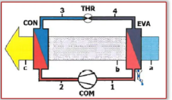
ADVANTAGES OF DRYING OF VEGETABLES USING THE INTEGRATED HEAT PUMP TECHNOLOGY 23 5. Jukka HEMILÄ, Päivi JARING – FINLAND
ACCELERATING IDEA TO MARKET PROCESS IN MANUFACTURING INDUSTRIES 27 6. Robert BERNERSTÄTTER – AUSTRIA
DATA MATURITY FOR SMART FACTORY APPLICATIONS – AN ASSESSMENT MODEL 31 7. Jasna TOLMAČ, Slavica PRVULOVIĆ, Dragiša TOLMAČ, Marija NEDIĆ – SERBIA
OIL PRODUCTS AND PUMPING STATIONS 37 8. Saliu Ojo SEIDU,Henry Kayode TALABI, A.S. AKANDE – NIGERIA
EFFECTS OF INOCULATION ON VARYING WALL THICKNESSES IN GRAY CAST IRON RECYCLING 41 9. Dragana DIMITRIJEVIĆ, Predrag ŽIVKOVIĆ, Janja BRANKOVIĆ,
Mirko DOBRNJAC, Žana STEVANOVIĆ – SERBIA / BOSNIA & HERZEGOVINA
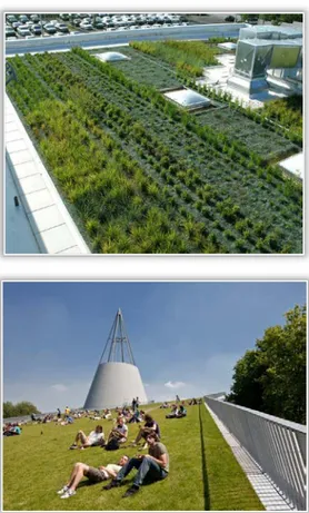
AIR POLLUTION REMOVAL AND CONTROL BY GREEN LIVING ROOF SYSTEMS 47 10. Petar DJEKIĆ, Biljana MILUTINOVIĆ, Mladen TOMIĆ – SERBIA
APPLICATION OF POLYURETHANE WASTE IN VIRGIN RUBBER BLENDS 51 11. Elvin OKUGIĆ, Milan JURKOVIĆ – BOSNIA & HERZEGOVINA
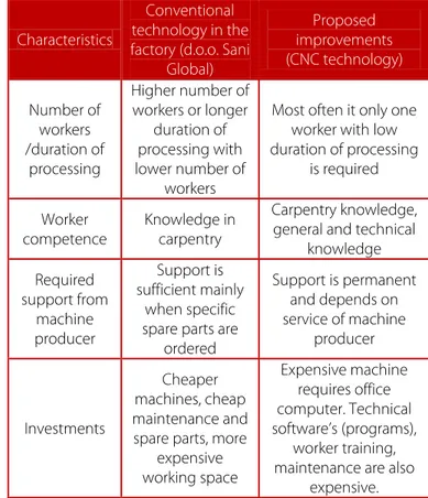
THE ANALYSIS OF TECHNOLOGICAL PROCESS IN MANUFACTURING FACILITY "SANI GLOBAL" AND PROPOSED MEASURES TO IMPROVE THE PROCESS 55 12. Ivana TERZIĆ, Vanja ŠUŠTERŠIČ, Katarina ĐONOVIĆ – SERBIA
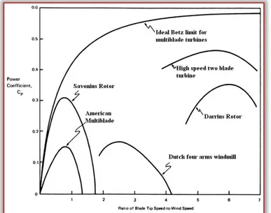
COMPARATIVE ANALYSIS OF GEOTHERMAL HEAT PUMPS 59 13. Mukrimin Sevket GUNEY, Faruk GUNER, Atılgan ALTİNKOK, Birkut GULER – TURKEY
HYDROKINETIC TECHNOLOGIES AND APPLICATION 63 14. Snežana DRAGIĆEVIĆ, Elisabetta GHIRARDELLI, Roberto RANZI – SERBIA / ITALY
HYDROMETEOROLOGICAL MONITORING IN WEST MORAVA RIVER BASIN (SERBIA) 67 15. W.A. AYOOLA, M.A. BODUDE, H. ONOVO, A. OYETUNJI – NIGERIA
EFFECTS OF ZINC POWDER ADDITION TO VILLA GLOSS AND SILKA LUX MARINE ENAMEL PAINTS ON CORROSION RESISTANCE OF MILD STEEL 71
10 | F a s c i c u l e 1
16. Slavica PRVULOVIC, Predrag MOSORINSKI, Dragisa TOLMAC, Ivan PALINKAS – SERBIA
CHIP SHAPE AS MACHINABILITY PARAMETER IN THERMOPLASTIC TURNING 77 17. Uroš ŽUPERL, Franc ČUŠ – SLOVENIA
TEACHING-LEARNING BASED ALGORITHM COMBINED WITH CUTTING FORCE 81 18. Stefan SCHMIDT,Benjamin S. G. SCHMIDT – GERMANY / NETHERLANDS
MAINTAINABILITY, RELIABILITY AND SERVICEABILITY – INDUSTRIAL EXAMPLES AUTOMOTIVE INDUSTRY 87 19. J.I. ORISALEYE, S.O. ISMAIL, M. OGBONNAYA, A.A. OGUNDARE – NIGERIA / UNITED KINGDOM
DEVELOPMENT AND PERFORMANCE EVALUATION OF A SOLAR WATER STILL 91 20. Vasil VLASEV – BULGARIA
DETERMINING THE MAXIMUM CUTTING FORCE IN BAND SAW MACHINES WITH REGARD TO THE INFLUENCE OF THE RUN–OUT OF THE BAND SAW BLADE 97 21. Milan RACKOV, Siniša KUZMANOVIĆ, Maja ČAVIĆ, Ivan KNEŽEVIĆ – SERBIA
INFLUENCE OF OPERATING AND AMBIENT TEMPERATURE ON LOAD CAPACITY OF UNIVERSAL WORM GEAR
REDUCER 101
22. Najla FATHALLA, Abdelnaser OMRAN – LIBYA / MALAYSIA
HOUSING POLICIES AND STRATEGIES IN LIBYA: BRIEF AN OVERVIEW 105 23. Izudin DELIĆ, AmeI MEŠIĆ – BOSNIA & HERZEGOVINA
CFD ANALYSIS OF FLUID STREAMING IN ROTARY DRYER 109 24. Mohamed Najeh LAKHOUA, J. BEN SALEM, Lilia EL AMRAOUI – TUNISIA
THE NEED FOR SYSTEM ANALYSIS BASED ON TWO STRUCTURED ANALYSIS METHODS SADT AND SA/RT 113 25. Goran VUJNOVIĆ, Jasmina PERIŠIĆ, Marina MILOVANOVIĆ, Ljiljana RADOVANOVIĆ – SERBIA
USING SCADA APPLICATIONS IN WATER SUPPLY SYSTEM 119
*** MANUSCRIPT PREPARATION – GENERAL GUIDELINES 125
The ACTA TECHNICA CORVINIENSIS – Bulletin of Engineering, Tome XI [2018], Fascicule 1 [January – March], includes scientific papers presented in the sections of:
» The 13th International Conference on Accomplishments in Mechanical and Industrial Engineering – DEMI 2017, organized by University of Banja Luka, Faculty of Mechanical Engineering, in Banja Luka, BOSNIA & HERZEGOVINA, 26 - 27 May 2017. The current identification number of the papers are the #1–4, #9–12, #21 and #23, according to the present contents list.
» The 9th International Conference “Management of
Technology – Step to Sustainable Production” – MOTSP 2017, organized by Faculty of Mechanical Engineering and Naval Architecture of the University of Zagreb, CROATIA and University North, Varaždin, CROATIA, in Dubrovnik, CROATIA, 5 – 7 April 2017. The current identification number of the papers are the #5–6 and #17–18, according to the present contents list.
» The 7th International Conference Industrial Engineering and Environmental Protection 2017 – IIZS 2017, organized by University of Novi Sad, Technical Faculty "Mihajlo Pupin", in Zrenjanin, SERBIA, 12 – 13 October 2017.
The current identification number of the papers are the #7, #13–14, #16 and #25, according to the present contents list.
Also, the ACTA TECHNICA CORVINIENSIS – Bulletin of Engineering, Tome XI [2018], Fascicule 1 [January – March] includes original papers submitted to the Editorial Board, directly by authors or by the regional collaborators of the Journal.
ISSN: 2067-3809
copyright © University POLITEHNICA Timisoara, Faculty of Engineering Hunedoara, 5, Revolutiei, 331128, Hunedoara, ROMANIA
1.
Sasa PAVLOVIC,
2.Evangelos BELLOS,
3.Velimir STEFANOVIC,
4.Christos TZIVANIDIS
EXPERIMENTAL AND NUMERICAL INVESTIGATION OF A SOLAR DISH
COLLECTOR WITH SPIRAL ABSORBER
1,3. Department of Energetics and Process technique, Faculty of Mechanical Engineering, University in Niš, SERBIA 2,4. Department of Thermal Engineering, National Technical University of Athens, Zografou, Athens, GREECE
Abstract: The objective of this work is to investigate experimentally and numerically a solar dish collector and to examine the impact of possible improvements in its performance. The examined solar dish collector has a spiral absorber and it is lightweight, fact that makes the system to have low cost and to be sustainable. The experimental results are compared with the results of a developed numerical model written in EES (Engineering Equation Solver) and validation between the results is observed. The validated numerical model is used for further investigation of the solar collector for operation with Therminol VP1. In the first part of the investigation, the impact of flow rate on the thermal and the exergetic performance is examined, and finally 200 l/h was found as the best solution. The next part is the optical investigation of the collector and greater optical efficiencies are tested. It is found that optical performance of 75% leads to maximum exergetic efficiency of 22.49%, three times greater than 7.49% which corresponds to the present situation of 35% optical efficiency. In the last part of this study, the selective absorber is compared to the non-selective of the real system and it is found that the use of the first is vital for achieving high operating temperature levels. The results of this study can be used as guidelines for the future improvement of the present facility.
Keywords: Solar dish collector, thermal analysis, exergy analysis, parametric analysis INTRODUCTION
Solar energy utilization is vital for facing the present environmental problems and the fossil fuel depletion [1-3]. The use of concentrating collectors is one of the most promising ways for producing, heating, cooling, electricity and other useful products with a clean and cheap way [4-6]. Solar dish concentrators gain more and more attention the last years and a lot of research has been focused on them. Reddy et al. [7] investigated a modified cavity receiver of a solar dish collector with a numerical model for the natural convection heat losses of the receiver. This configuration includes a tube wound in a hemispherical geometry which is covered with insulation to reduce the thermal losses. Daabo et al. [8] examined three receiver geometries: cylindrical, conical and spherical.
In every case, a helical tube was used in order to utilize the solar energy. According to their results, the conical shape is the best choice among the examined cases. Przenzak et al. [9] examined a solar dish collector with a two optical elements and a curved radiation absorber. This system was designed for operation in high temperature levels and there was a special design for achieving this goal. More specifically, a parametric analysis has been applied in order the optimum receiver location and the most suitable mass flow rate to be determined.
In this study, the spiral absorber is examined in a lightweight receiver which is manufactured by 11 reflecting petals. The basic idea is to create a low cost solar collector which can operate in medium high temperature levels, ideal for polygeneration systems. In literature, there are also preliminary studies about the design of this system [10-12]. In
this study, his system is examined experimentally and also a thermal model is developed in order to examine the collector parametrically. The objective of this paper is to show how this configuration can be improved in the future in order to be commercialized.
METHODS
⧉ The examined setup
In this section, the examined experimental set up is described. The solar dish collector is given in figure 1. The first innovation of this design is the spiral absorber which leads to a relative uniform heat flux distribution. The next innovations are the low cost and the lightweight structure of this collector. The main characteristics of the collector are given in the flow chart of figure 2 and in Refs [10-12].
Figure 1. The examined solar dish collector ⧉ The numerical model
The developed numerical model is based on the energy balance on the spiral receiver and it is developed in EES (Engineering Equation Solver) by F-Chart [13]. This model has
12 | F a s c i c u l e 1
been also used and validated in other literature studies [14-15] and it is presented in figure 2 with the suitable modifications. Also it is essential to state that some useful references have been used for the utilized equations [15-19].
Figure 2. The flow chart of the developed numerical model ⧉ Followed methodology
The first part of this study (subsection 3.1) is the validation of the developed thermal model. Experimental results are used in order this model to be tested. For these tests, water has been used as working fluid with volumetric flow rate of 200 l/h. The experiments have performed the time period of August-September 2016, in the solar laboratory of the Faculty of Mechanical Engineering in the University of Nis (latitude 43o19’ and longitude 21o54’). Moreover, it is essentially to state that for the real experimental setup, the optical efficiency has been estimated to 35%, after experimental tests. The reason for this low value is the low quality reflectance and manufacturing errors in the paraboloid shape of the concentrator. In the parametric studies, different parameters of the examined solar collector are investigated. In all these studies (subsections 3.2, 3.3 and 3.4) the working fluid is Therminol VP1 [20] because this is the best candidate for operation in higher temperature levels. In section 3.2, the flow rate is investigated, in section 3.3 the optical efficiency and in section 3.4 the receiver emittance. The emittance of the real collector is about 0.9 because the absorber is non-selective, while the case of selective absorber with emittance equal to 0.1 is examined numerically.
3. RESULTS
⧉ Model validation
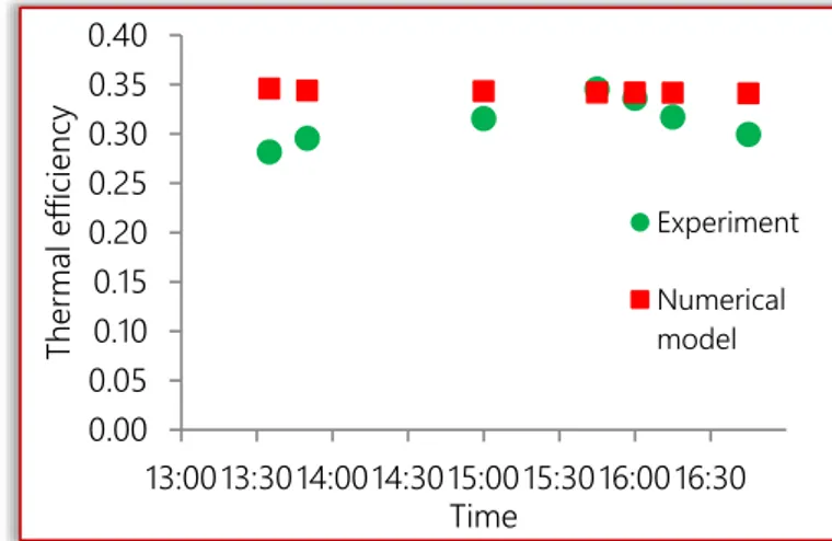
In this subsection, the experimental results are used for validation of the developed model. Figure 1 illustrates the thermal efficiency and it is obvious that the experimental and the numerical results are close to each other, with mean deviation close to 5%. Thus, the developed numerical model is validated. Also it is essential to state that the thermal efficiency of the real collector operating with water (in low temperature levels) is close to 34%; low value which has to be increased for making this collector a competitive technology.
Figure 3. Thermal efficiency comparison between experimental and numerical results
⧉ Flow rate investigation
In this subsection, thermal oil is used and six different flow rates are examined. Figure 4 show that higher flow rate leads to higher thermal efficiency. After 200 l/h, all the curves tend to one, so this flow rate is selected as the optimum one. Figure 5 depicts the exergetic performance of the collector for the same examined cases. In low temperature levels, the lower mass flow rate is the best candidate, while in higher temperature levels, higher mass flow rates have to be used. Generally, the maximum exergetic efficiency is observed in the region between 145 oC to 165 oC and it is about 0.075; a low value which is explained by the low optical efficiency.
Figure 4. Thermal efficiency for various flow rates
Figure 5. Exergetic efficiency for various flow rates 0.00 0.05 0.10 0.15 0.20 0.25 0.30 0.35 0.40 13:0013:3014:0014:3015:0015:3016:0016:30 Ther m al ef fic ienc y Time Experiment Numerical model -0.05 0.05 0.15 0.25 0.35 30 60 90 120 150 180 210 240 270 300 Ther m al ef fic ienc y
Inlet temperature (oC)
V=350 l/h V=300 l/h V=250 l/h V=200 l/h V=150 l/h V=100 l/h 0.00 0.02 0.04 0.06 0.08 30 60 90 120 150 180 210 240 270 300 Ex er get ic ef fic ienc y
Inlet temperature (oC)
V=350 l/h V=300 l/h
V=250 l/h V=200 l/h
⧉ Optical efficiency investigation
The optical efficiency of the present collector is about 35%. This low value can be increased by using higher quality reflector and improving the shape of the reflector. In this section, the thermal and the exergetic efficiency are examined parametrically with the optical efficiency for thermal oil flow rate equal to 200 l/h. Figure 6 exhibits the thermal efficiency and it is obvious that all the curves seem to be parallel. The interesting result is that higher optical leads to higher thermal efficiency and to higher stagnation temperature. This temperature is the one which leads to zero thermal performance. This results is important for the determining the temperature operating range of the collector in every case.
Figure 6. Thermal efficiency for various optical efficiencies Figure 7 depicts the exergetic efficiency for the similar cases. Higher optical efficiency leads to higher exergetic performance. Moreover, higher optical efficiency leads to the exergetic efficiency to be maximized in greater temperature level. This is an interesting result which indicates that the exergetic performance of the collector is associated with the optical performance of it. For 75% optical efficiency, the maximum exergetic efficiency is 22.49% and it is observed at 210oC inlet temperature. For the optical efficiencies of 65%, 55%, 45% and 35%, the respective maximum exergetic performances are 18.41%, 14.52%, 10.85% and 7.46%, while the respective inlet temperature levels for exergetic maximization are 200oC, 190oC, 175oC and 155oC.
Figure 7. Exergetic efficiency for various optical efficiencies
⧉ Emittance investigation
In the last subsection, the impact of emittance on the collector performance is investigated by using 35% optical efficiency and 200 l/h thermal oil flow rate.
Figure 8. Thermal and exergetic efficiencies for the examined absorbers
Figure 8 show the thermal and the exergetic efficiencies for the non-selective absorber case (emittance equal to 0.9 – real case) and for selective absorber case (emittance 0.1). It is obvious that the performance with selective absorber is higher and the collector can operate in higher temperature levels. It is important to state that the non-selective case presents maximum exergetic efficiency for 155 oC and the selective for 265 oC with 7.49% and 11.17% respectively. 4. CONCLUSIONS
In this paper, a solar dish collector with spiral absorber is examined experimentally and numerically. The developed numerical model is validated with the experimental results for operating with water. Moreover, the developed numerical model with EES is utilized for examining the solar collector in various operating conditions, by changing the inlet temperature levels and the mass flow rates. Moreover, the impacts of the optical efficiency and of the absorber emittance are examined. The most important conclusions are summarized below:
» The present collector has low efficiency (about 34%) and it can operate up to 300 oC.
» The minimum suitable flow rate for thermal oil is 200 l/h for efficient operation.
» Higher optical efficiency makes the system to operate with higher thermal and exergetic efficiency, as well as to increase the maximum temperature close to 400oC. » The maximum exergetic efficiency of the present system
(optical efficiency equal to 35%) is about 7.49% and it is observed for 155oC, while for optical efficiency equal to 75%, the maximum exergetic efficiency is 22.49% for 210oC.
» The influence of the absorber emittance on the results is critical and it can make the collector to perform better and to operate in higher temperatures.
0.0 0.5 1.0 0 50 100 150 200 250 300 350 400 450 Ther m al ef fic ienc y
Inlet temperature (oC)
ηopt = 35% ηopt = 45% ηopt = 55% ηopt = 65% ηopt = 75% 0.00 0.10 0.20 0.30 0 50 100 150 200 250 300 350 400 450 Ex er get ic ef fic ienc y
Inlet temperature (oC)
ηopt = 35% ηopt = 45% ηopt = 55% ηopt = 65% ηopt = 75% 0.00 0.05 0.10 0.15 0.00 0.10 0.20 0.30 0.40 30 60 90 120 150 180 210 240 270 300 Ex er get ic ef fic ienc y Ther m al ef fic ienc y
Inlet temperature (oC)
Thermal efficiency (selective) Thermal efficiency (non selective) Exergetic efficiency (selective) Exergetic efficiency (non selective)
14 | F a s c i c u l e 1
Nomenclature
A Area, m2 μ Dynamic viscosity, Pa s
C Concentration ratio, - ρ Density, kg/m3
cp Specific heat capacity,
kJ/kg K σ Stefan–Boltzmann constant
D Diameter, mm Subscripts and superscripts
E Exergy flow, W a aperture
fr Friction factor, - abs absorbed
Gb Solar beam radiation, W/m2 air ambient air
h Convection coefficient,
W/m2K am ambient
k Thermal conductivity,
W/mK ex exergetic
L Tube length, mm fm mean fluid
m Mass flow rate, kg/s in inlet
Nu Mean Nusselt number, - loss losses
Pr Prandtl number, - opt optical
Q Heat flux, W out outlet
Re Reynolds number, - r receiver
T Temperature, K ri inner receiver
u Working fluid velocity, m/s ri,max inner receiver max
V Volumetric flow rate, m3/s ri,min inner receiver min
Vair Ambient air velocity, m/s ro outer receiver
Greek symbols s solar
ε Emittance, - sun sun
ΔP Pressure drop, kPa th thermal
η Efficiency, - u useful
Note
This paper is based on the paper presented at 13th International Conference on Accomplishments in Mechanical and Industrial Engineering – DEMI 2017, organized by University of Banja Luka, Faculty of Mechanical Engineering, in Banja Luka, BOSNIA & HERZEGOVINA, 26 - 27 May 2017.
References
[1] Bellos, E., Tzivanidis, C., Moschos, K., Antonopoulos, K.A. (2016). Energetic and financial evaluation of solar assisted heat pump space heating systems. Energy Conversion and Management, vol. 120, p. 306-319
[2] Bellos, E., Tzivanidis, C., K., Antonopoulos, K.A. (2016). Exergetic and energetic comparison of LiCl-H2O and LiBr-H2O working pairs in a solar absorption cooling system. Energy Conversion and Management, vol. 123, p.453-461
[3] Bellos, E., Korres, D., Tzivanidis, C., K., Antonopoulos, K.A. (2016). Design, simulation and optimization of a compound parabolic collector. Sustainable Energy Technologies and Assessments, vol. 16, p. 53-63
[4] Bellos, E., Tzivanidis, C., K., Antonopoulos, K.A. (2016). Parametric investigation and optimization of an innovative trigeneration system. Energy Conversion and Management, vol. 127, p. 515-525
[5] Bellos, E., Tzivanidis, C., K., Symeou, C., Antonopoulos, K.A. (2017). Energetic, exergetic and financial evaluation of a solar driven absorption chiller – A dynamic approach. Energy Conversion and Management, vol. 137, p. 34-48
[6] Bellos, E., Mathioulakis, E., Tzivanidis, C., Belessiotis, V., Antonopoulos, K.A. (2016). Experimental and numerical investigation of a linear Fresnel solar collector with flat plate receiver. Energy Conversion and Management, vol. 130, p. 44-59
[7] Reddy, K.S., Vikram, T.S., Veershetty, G. (2015). Combined heat loss analysis of solar parabolic dish – modified cavity receiver for superheated steam generation. Solar Energy, vol. 121, p. 78-93
[8] Daabo, A.M., Mahmoud, S., Al-Dadah, R.K. (2016). The effect of receiver geometry on the optical performance of a small-scale solar cavity receiver for parabolic dish applications. Energy, vol. 114, p. 513-525
[9] Przenzak, E., Szubel, M., Filipowicz, M. (2016). The numerical model of the high temperature receiver for concentrated solar radiation. Energy Conversion and Management, vol. 125, p. 97-106
[10] Pavlovic, S.R., Vasiljevic, D.M., Stefanovic, V.P., Stamenkovic, Z.M., Bellos, E.A., Optical analysis and performance evaluation of a solar parabolic dish concentrator. Thermal Science, vol. 20, no. S5, p. 1237-1249
[11] Pavlović, S.R., Bellos, E., Stefanović, V.P., Tzivanidis, C., Stamenković, Z.M. (2016). Design, simulation and optimization of a solar dish collector spiral-coil thermal absorber. Thermal science, vol. 20, no. 4, p. 1387-1397
[12] Pavlovic, S.R., Stefanovic, V., Bellos, E. (2016). Design and Simulation of a Solar Dish Concentrator with Spiral-Coil Smooth Thermal Absorber, In Proceedings of “8th International Symposium on Renewable Energy Exploitation of Energy Sources”, p. 88-95, 31th March – 2nd April Subotica, Serbia [13] F-Chart Software, Engineering Equation Solver (EES); 2015.
(http://www.fchart.com/ees)
[14] Bellos, E., Tzivanidis, C., Antonopoulos, K.A. (2016). A detailed working fluid investigation for solar parabolic trough collectors. Applied Thermal Engineering, vol. 114, p. 374-386 [15] Bellos, E., Tzivanidis, C., Antonopoulos, K.A, Daniil, I. (2016). The
use of gas working fluids in parabolic trough collectors – An energetic and exergetic analysis. Applied Thermal Engineering, vol. 109, p. 1-14
[16] Duffie, J.A., Beckman, W.A. (2006). Solar Engineering of Thermal Processes, 3rd edition, Wiley, Hoboken, NJ, USA
[17] Leinhard IV, J., Leinhard V, J. (2012). A Heat Transfer Textbook, 4th edition, Phlogiston Press, USA
[18] Djordevic, M.L., Stefanovic, V.P., Mancic, M.V. (2016). Pressure drop and stability of flow in Archimedean spiral tube with transverse corrugations. Thermal Science, vol. 20, no. 2, p. 579-591
[19] Bellos, E., Tzivanidis, C., Antonopoulos, K.A., Gkinis, G. (2016). Thermal enhancement of solar parabolic trough collectors by using nanofluids and converging-diverging absorber tube. Renewable Energy, vol. 94, p. 213-222
[20] http://www.therminol.com/pages/bulletins/therminol_VP1
ISSN: 2067-3809
copyright © University POLITEHNICA Timisoara, Faculty of Engineering Hunedoara, 5, Revolutiei, 331128, Hunedoara, ROMANIA
1.Stojana VESKOVIĆ BUKUDUR, 2.Aleš NAGODE, 3.Blaž KARPE, 4.Janez KOVAČ, 5.Stjepan KOŽUH, 6.Milan BIZJAK
PACK ALUMINIZATION PROCESS OF HEAT RESISTANT FeCrAl AND NiCr ALLOYS
1.Hidria AET d.o.o., Poljubinj 89a, 5220 Tolmin, SLOVENIA
2,3,6.University of Ljubljana, Faculty of Natural Sciences and Engineering, Ljubljana, Aškerčeva 12, 1000 Ljubljana, SLOVENIA 4.Institute Josef Stefan, Jamova c. 39, 1000, Ljubljana, SLOVENIA
5.University of Zagreb, Faculty of Metallurgy, Sisak, Aleja n. h. 3, 44103 Sisak, CROATIA
Abstract: Pack aluminization process is one of the possible production methods to improve oxidation resistance at high temperatures of various types of metallic materials. It is a chemo-thermal process where products are embedded in the powder mixture, consisting of Al powder, halide activator NH4Cl, and inert diluent Al2O3 powder, and annealed at high temperature. This exposure to high temperature causes the Al diffusion into the base material and formation of the aluminide surface layer. During the component service at elevated temperatures, the oxidation resistance is obtained due to the constant formation of an aluminium oxide film that forms on the aluminide surface layer and acts as an oxygen impermeable barrier. In the present study, FeCrAl and the NiCr heat resistant alloys in the form of 1mm thick sheet were aluminized at various process parameters. The effect of time, temperature, concentration of aluminium and halide activator in the powder mixture as well as the influence of furnace atmosphere on coating formation mechanism, mass gain and the thickness of the aluminide diffusion layer was evaluated by scanning electron microscopy, X-ray photoelectron spectroscopy and micro hardness analytic techniques. Isothermal exposure tests at 1200 °C for 24h in air were conducted and compared with untreated samples for high temperature oxidation resistance estimation.
Keywords: Aluminizing, heat resistant alloys, FeCrAl, NiCr, high temperature oxidation INTRODUCTION
Aluminizing is a widely used process to protect materials, particularly metals and alloys against high temperature oxidation and hot corrosion attack. In this process the metal to be coated is placed in a powder pack consisting essentially of the coating element source such as pure aluminium or aluminium alloy (Cr-Al), an activator such as halide salts AlF3, NaCl, NH4Cl and NH4F and an inert filler material, usually alumina [1]. The process is carried out at atmospheric pressure in flowing hydrogen or in an inert atmosphere at a temperature between 700 °C and 1150 °C. The aluminizing process can be divided into three steps: (a) gaseous diffusion, (b) surface reaction and (c) solid diffusion. At the coating temperature halide activator reacts with the metal elements in the powder pack and form a series of metal halide vapour species with characteristic partial pressure distribution that is determined by their thermodynamic stability in a particular powder pack. The coating is formed via reduction reaction of metal halide vapours at the substrate surface and subsequent solid state diffusion between metal elements and substrate [2,3].
The thermodynamics and kinetics of the aluminizing process are defined by the pack components and operating conditions like temperature, time and atmosphere [4]. Two critical issues for the application of aluminide coating have been identified: (i) loss of Al from the coating into the substrate which limits coating lifetime, (ii) the difference in thermal expansion coefficient (CTE) between aluminide
coating and the substrate, which can cause mechanical damage (cracks) to the coating [5].
EXPERIMENTAL PROCEDURE
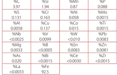
The substrate alloys used in this study were a commercial ferritic alloy Fe-Cr-Al (Kanthal AF) and a commercial austenitic alloy Ni-Cr (Nicrothal 80); the composition is listed in Table 1.
Table 1. Chemical composition of the coated alloys in wt.%. Alloy Ni Cr Fe Mn Si Al Ti Kanthal
AF 0.4 21.0 Bal. 0.2 0.2 5.5 1.0 Nicrothal
80 Bal. 20.0 1.0 0.5 1.3 - - Flat coupons (20 x 10 x 0.7 mm) were ultrasonically cleaned in an alcohol, dried and immediately embedded in a powder pack, which consist of the deposition element (Al), an activator (NH4Cl) and an inert filler (Al2O3), and semi-sealed in alumina crucible. The crucible is heat treated in a tube furnace under an Ar-5%H2 atmosphere. Process parameters of the aluminizing process are process time, process temperature and the powder pack. The coating time was varied from 0.5 to 2.5 hours and the process temperature from 670°C to 750°C. The heating rate was 10°C/min and the cooling rate from the process temperature to 200 °C was 5 °C/min. The Al to NH4Cl mass ratio in the powder mixture was 3 (21 wt.% Al, 7 wt.% NH4Cl, 72 wt.% Al2O3) for all aluminizing experiments. Coated specimens were cleaned with a brush and then put into ultrasonic bath and cleaned in an alcohol.
Cross sections of samples for microstructure observations were prepared by standard metallographic preparation by
16 | F a s c i c u l e 1
grinding and polishing. Optical microscope AXIO CSM 700 and scanning electron microscope Jeol JSM 5610 with energy dispersive X-ray spectroscopy (EDS) were used for the microstructure observations.
The phase constitution of the as deposited coatings was examined by X-ray diffraction (XRD), using Cu Kα radiation. The oxidation resistance of the samples was investigated under isothermal conditions by thermobalance Netzsch STA 429 at 1200 °C, 24 h in a laboratory air atmosphere. Samples were heated at a rate of 20 K/min, followed by cooling at the rate 20 K/min.
RESULTS AND DISCUSSION
⧉ Coating thickness as a function of time and temperature
Aluminium was successfully deposited onto Fe-Cr-Al an Ni-Cr alloy in the form of 0.7 mm sheet through the halide activated aluminizing process at different coating temperature and time. The coatings show some irregularities and a small pore size but are free of cracks. The number of irregularities in coatings increases with coating temperature. After aluminising, coating thickness measurements were performed at various sites.
Figure 1 shows the SEM cross sections of aluminide coatings on Fe-Cr-Al and Ni-Cr alloy deposited at 670 °C for 1.5h and Figure 2 aluminide coatings on both alloys deposited at 730 °C for 1.5 h. The aluminide coating is thicker in the case of Fe-Cr-Al alloy because of a higher diffusion rate of Al in Fe-Fe-Cr-Al alloy, especially at higher temperature.
(A)
(B) Figure 1. SEM image of FeCrAl (A) and NiCr alloy (B) aluminized
at 670°C, 1.5 h
(C)
(D) Figure 2. SEM image of FeCrAl (C) and NiCr alloy (D) aluminized
at 730°C, 1.5 h
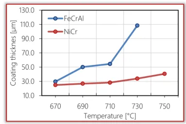
Figure 3. The average aluminide coating thickness as a function of aluminizing temperature at a constant annealing time 1.5 h
Figure 4 . The average aluminide coating thickness as a function of time at a constant temperature 690 °C
A
B CD
10.0 30.0 50.0 70.0 90.0 110.0 130.0 670 690 710 730 750 Co at in g th ickn es [µ m ] Temperature [°C] FeCrAl NiCr 15.0 35.0 55.0 75.0 0.5 1 1.5 2 2.5 3 Co at in g th ickn es s [µ m ] Time [h] FeCrAl NiCrFigure 3 shows the average coating thickness as a function of coating temperature at constant time. The data points for each coating temperature demonstrate that as the coating temperature is increased, the coating thickness increased. With an increase in aluminizing temperature from 670 °C to 730 °C at constant coating time 1.5 h, the coating thickness is increased threefold for Fe-Cr-Al alloy and thirty percent for Ni-Cr alloy. Figure 4 shows the average coating thickness as a function of coating time at constant temperature 690 °C. The thickness of the coating increase with time from 0.5 to 3 h for both alloys. Increase in thickness was much higher for Fe-Cr-Al alloy.
⧉ Scanning Electron Microscopy (SEM/EDS)
Chemical analysis of coating and substrate subsurface were performed by energy dispersive spectroscopy (SEM-EDS). Figure 5 shows the representative sample subjected to the coating temperature of 730 °C for 1.5h for the Fe-Cr-Al alloy and Figure 6 for the Ni-Cr alloy. Coating thickness ranged from 100 to 120 µm for Fe-Cr-Al alloy and 30 to 45 µm for Ni-Cr alloy.
Figure 5. SEM-EDX analysis of Fe-Cr-Al coated at 730 °C for 1.5 h
Figure 6. SEM-EDX analysis of NiCr coated at 730 °C for 1.5 h The coating on Fe-Cr-Al alloy is a dual phase mixture with dark and light areas. EDS analysis show that the dark phase is rich in aluminium and contain iron and a small amount of chromium. The light phase contains a smaller percentage of aluminium and iron, and a larger percentage of chromium. It
is evident that Fe-Cr-Al alloy forms a number of different phases. The formation of these phases depends on the diffusion of aluminium through the coating in direction to the substrate. The aluminium content increased in the direction to coating surface and the content of chromium and iron decreased.
On the other hand, aluminized layer on Ni-Cr alloy consists of two layers: the darker top layer (Area I), rich on aluminium, chromium and nickel and lighter subsurface layer (Area II), which contains smaller percentage of aluminium and a higher percentage of nickel and chromium. The average coating thickness is 35 µm, thickness of top layer is 15 µm followed by a sub layer of about 20 µm.
⧉ X-ray diffraction
X-ray diffraction (XRD) was used for phase identification of coatings. From these study it was established that for the coating time 1,5h at 730°C, the surface of the coated Fe-Cr-Al alloys consists mainly from α- Al8Fe5, β- Al5Fe2, γ- AlFe3 (see Figure 7a). According to the phase diagram Fe-Cr the iron forms a number of different intermetallic compounds such as: FeAl3, Fe2Al5, FeAl2, FeAl, Fe3Al, as well α-Al and α-Fe. Based on
the intensity of the scattered X-rays the largest content has Al5Fe2 phase.
Figure 7. XRD patterns of the aluminizing coating on Fe-Cr-Al substrate a) and NiCr substrate b)
Aluminized coating of Ni-Cr alloy comprises the following phases: α- Al3Ni2, β- Al, γ- Ni, δ- Cr, ε- Al3Ni (see Figure 7 b), with the largest proportion of the Al3Ni2 phase. From the results of XRD and SEM analysis, it can be concluded, that the upper layer (I) is comprised mainly of Al3Ni phase, and the layer (II) of Al3Ni2 phase, with continuously increased proportion of other phases according to the Al-Ni phase diagram. This finding is in a good agreement with [6]. They found out that Al3N2 is the major phase because of a very high diffusivity of Al3Ni2.
SUBSTRATE COATING
Principal elements in EDS analysis (wt.%)
hase O Al Cr Fe Co area 49.68 4.03 45.41 0.89 area 0.40 40.34 22.97 35.59 0.69 trate 3.82 21.22 73.84 SUBSTRATE COATING
Principal elements in EDS analysis (wt.%)
Phase Al Si Cr Mn Fe Ni Area I 48.97 0.26 10.76 0.13 0.34 39.54 Area II 37.55 0.50 11.50 0.10 0.37 49.98 Substrate 0.12 1.25 20.43 0.17 0.50 77.54 a) b)
18 | F a s c i c u l e 1
⧉ Oxidation test
The effectiveness of the aluminizing process was evaluated by the oxidation testing of the commercial Fe-Cr-Al 0.7 mm thick sheet in comparison with aluminized Fe-Cr-Al samples under isothermal conditions (thermo-balance Netzsch STA 429) at constant temperature of 1200 °C/24 h in a laboratory air atmosphere. Samples were heated and cooled at the same rate of 20 K/min. The results are presented by the relative mass gain versus time (Figure 8). According to the measurements, the initial oxidation rate of as received commercial Cr-Al sheets is higher than for aluminized Fe-Cr-Al samples (first 24 h). Because of short time of isothermal temperature exposure, further longer tests would be needed to determine whether or not the increased Al alloy content prolong the life time of the Kanthal AF sheet at 1200 °C [7].
Figure 8. Relative mass gain as a function of oxidation time in air at 1200°C (heating rate 20 K/min)
CONCLUSIONS
Within the work it was successfully prepared homogeneous aluminized layer on ferritic Kanthal AF (Fe-Cr-Al) and on austenitic Nicrothal 80 (Ni-Cr) with sufficient aluminium reservoir, which should enable the formation of protective alumina scale in oxidizing conditions.
The effect of Al activity in powder pack on the coating kinetics and structure was studied at several coating temperatures in the range from 650 to 750 °C for 0.5 to 2.5 hours. Samples in the form of sheet were uniformly aluminized at various times and temperatures. The dependence of coating thickness from temperature and time at constant powder pack was evaluated.
The coating is free of cracks with some imperfections like pores or porous area. According to SEM/EDS analyses of Fe-Cr-Al alloy aluminium content decreased from the coating surface to the substrate material, the content of chromium and iron increases. Aluminized layer on Fe-Cr-Al alloy contains intermetallic phases Al8Fe5, Al5Fe2 and AlFe3.
Analyses of the aluminized layer on Nicrothal 80 (Ni-Cr) alloy showed that aluminized layer consists of two layers. The upper layer, with higher percent of aluminium and the lower layer, with smaller percentage of aluminium and a higher percentage of nickel and chromium. The upper layer is
comprised mainly of Al3Ni phase, and the lower layer of Al3Ni2 phase, with continuously increased proportion of other phases in direction of the substrate alloy. The thickness of the layers increases with aluminizing time and temperature. Coating thickness is increased faster in Fe-Cr-Al alloy because of significantly higher diffusion rate of aluminium in KANTHAL AF alloy than in Nicrothal 80 alloy [8].
Note
This paper is based on the paper presented at 13th International Conference on Accomplishments in Mechanical and Industrial Engineering – DEMI 2017, organized by University of Banja Luka, Faculty of Mechanical Engineering, in Banja Luka, BOSNIA & HERZEGOVINA, 26 - 27 May 2017.
References
[1] Mévrel, C., Duret, R., Pichoir, P. (1986). Pack cementation processes. Material Science and Technology, Vol. 2, Issue 3, pp. 201-206.
[2] Gupta, B. K., Sarkhel, A. K., Seigle, L. L. (1976). On the kinetics of pack cementation. Thin solid films, Vol. 39, pp. 313-320. [3] Xiang, Z. D.J. S. Burnell-Gray, S., Datta, P. K. (2001). Aluminide
coating formation on nickel-base super alloys by pack cementation process. Surface & Coatings technology, Vol. 36, Issue 23, pp. 5673–5682.
[4] Zhang, Y. (2008). Formation of aluminide coatings on the Fe-based alloys by chemical vapour deposition. Surface & Coatings technology, Vol. 202, pp. 3830-3849.
[5] Kung, S. C., Rapp R. A. (1987). Fundamental study of aluminization of iron by pack cementation at 900°C. Surface and coatings technology, Vol. 32, pp. 41-56.
[6] Seigle, L. L. (1982) Kinetics of formation and microstructure of aluminide coatings on Ni-Cr alloys, Thin Solid Films, Vol. 95, 1982, pp. 47-56.
[7] Bennett, M.J., Nicholls, J.R., Simms, N.J., Naumenko, D., Quadakkers, W.J., Kochubey, V., Fordham, R., Bachorczyk, R., Goossens, D., Hattendorf, H., Smith, A.B., Britton, D. (2005). Lifetime extension of FeCrAlRE alloys in air: Potential roles of an enhanced Al-reservoir and surface pre-treatment. Materials and Corrosion, Vol. 56, Issue 12, pp. 854–866. [8] Goward, G. W., Boone, D. H. (1971). Mechanisms of
Formation of diffusion Aluminide Coatings on Nickel-Base Superalloys. Oxidation of Metals, Vol. 3, No. 5, pp. 475-495.
ISSN: 2067-3809
copyright © University POLITEHNICA Timisoara, Faculty of Engineering Hunedoara, 5, Revolutiei, 331128, Hunedoara, ROMANIA
1.
Slobodanka BOLJANOVIĆ,
2.Stevan MAKSIMOVIĆ,
3.Strain POSAVLJAK
CRACK PROPAGATION ANALYSIS OF CYCLICALLY LOADED STRUCTURAL
COMPONENTS
1.Mathematical Institute of SASA, Kneza Mihaila 36, Belgrade, SERBIA 2.VTI, Ratka Resanovića 1, Belgrade, SERBIA
3.Faculty of Mechanical Engineering, Banja Luka, BOSNIA & HERZEGOVINA
Abstract: The present paper proposes a computational model for the failure analysis of finite plate with quarter-elliptical corner crack located at a hole. Such a theoretical investigation takes into account the stress intensity factor calculation and fatigue life estimation. Fracture mechanics based analytical approach is employed to analyze the stress-intensity behaviour, whereas the stress-ratio dependence crack growth model is applied for assessing fatigue life to failure. The crack growth estimations show a good correlation with experimental data.
Keywords: fatigue, quarter-elliptical crack, stress-intensity behaviour, residual life calculation INTRODUCTION
The integrity of engineering structures may be often threatened by fatigue crack-like flaws, i.e. damages during service operations. Therefore, significantly important aspect is to estimate the failure strength of components by taking into account reliable fracture mechanics based computational models.
Under cyclic loading, the crack propagation behaviour can be theoretically examined either as through-the-thickness crack situations or surface problems (quarter-elliptical corner crack, semi-elliptical crack and embedded-elliptical crack) through the stress analysis and residual life assessment by means of analytical methods and numerical approaches. Thus, Elber [1] suggested the crack closure concept, whereas Walker [2] and later Kujawski [3] proposed the two-parameter driving force model for the fatigue life estimations. Glinka et al. [4] found that the damage accumulation ahead of the crack tip can be employed to describe the crack growth rate. Furthermore, different fracture mechanics based numerical models such as: the finite element alternating method [5], the boundery integral equation method [6], the finite element method with singularity elements [7, 8] can be applied to assess the stress-intensity behaviour under fatigue conditions.
In the present paper, a mathematical model is developed for fatigue failure analysis of quarter-elliptical corner crack emanating from a hole. The proposed model considers the stress-intensity analysis and fatigue life estimation for depth and surface crack length directions. Relevant experimental crack growth data are employed to verify the predictive capability of failure assessments.
RESIDUAL LIFE ESTIMATION UNDER CYCLIC LOADING The complex interaction of applied load and environment can often endanger the service life of engineering structures due to appearance of fatigue failure. In order to ensure safe exploitation, the reliable computational models for the fatigue analysis have to be developed by taking into account appropriate fracture mechanics principles. Thus, the
propagation of quarter-elliptical corner crack emanating from a hole is herein theoretically examined through the crack growth law proposed by Walker [2[ in depth and surface crack directions, as follows:
( )
(
)
(
)
2 m IA A R 1 b , a K C dN da A − ∆ = and(
( )
)
(
)
2 m IB B R 1 b , a K C dN db B − ∆ = (1a-b)where a, b and ∆KIA, ∆KIB are the crack length and the stress intensity factor in depth and surface crack directions, respectively, R is the stress ratio and CA, CB, mA, mB denote material constants experimentally obtained.
In the residual strength assessment, the final number of loading cycles is computed by integrating the relationship related to the crack growth rate for depth and surface crack direction, respectively i.e.
(
)
( )
(
)
∫
∆− = f 0 A a a A IA m 2 b , a K C da R 1 N and(
)
( )
(
)
∫
∆− = f 0 B b b B IB m 2 b , a K C db R 1 N (2a-b)where a0, b0 and af, bf are initial and final crack lengths in depth and surface direction, respectively.
Since the relationships for the crack growth rate and the stress intensity factor are the complex-valued functions, the numerical integration based on the Euler's algorithm is taken into account. Thus, according to the software program here examined, the fatigue life to failure is estimated by applying Eqs. (2a)-(2b) step-by-step for appropriate crack growth increments.
STRESS-INTENSITY ANALYSIS OF QUATER-ELLIPTICAL CORNER CRACK
From the fracture mechanics theoretical point of view, the crack propagation under cyclic loading may be examined if the geometry of structural component together with
20 | F a s c i c u l e 1
parameters related to material and external loading are involved through the stress intensity factor. In the present study, the stress-intensity behaviour of the quarter-elliptical corner crack emanating from a hole (Fig. 1) is analyzed by taking into account the following relationship [9]:
φ π π ∆ = ∆ g w 2 D cos 1 f M Q a S KI e 1 (3)
where ∆KI is the stress intensity factor range, ∆S denotes applied stress/load, D and w are diameter and width of the plate, respectively. Further, Q, Me, f1 and gφ represent fracture
mechanics based functions related to crack configuration and loading, expressed in the following way [9]:
≤ + = 1.0 b a , b a 47 . 1 1 Q 1.64 (4) 1 w p 1 1 e f t a M a b Q M M − + = (5) ≤ ≤ − = 1.0 b a 02 . 0 , b a 1 . 0 2 . 1 M1 (6) 2 b a 8 2 p + = (7) 4 3 2 1
0
.
707
0
.
18
6
.
55
10
.
54
6
.
85
f
=
−
λ
+
λ
−
λ
+
λ
(8)(
φ)
+ = λ 85 . 0 cos D b 2 1 1 (9) − + π = b w b D 2 cos 1 fw1 (10)(
− φ)
+ + = φ 1 sin t a 35 . 0 1 . 0 1 g 2 (11) where t is the thickness of the plate and φ denotes parametric angle of ellipse.Figure 1. Geometry of the plate with quarter-elliptical corner crack emanating from a hole (a - depth direction, b – surface
direction). NUMERICAL APPLICATIONS
In the present Section, the failure behaviour of quarter-elliptical corner crack emanating from a hole is theoretically examined through the proposed computational model. Such fatigue crack growth investigation takes into account the stress intensity factor calculation and the residual life estimation.
⧉ The crack growth estimation under cyclic loading The fatigue strength of the plate with quarter-elliptical crack emanating from a hole (Fig. 1) is tackled through the residual life calculation.
(a)
(b)
(c)
(d) Figure 2. The fatigue failure analysis of the plate:
(a) ∆KA-a, (b) da/dN-a, (c) a-N, (d) b-N.
0 5 10 15 20 25 30 35 0 2 4 6 8 10 12 14 a [m] (x10-3) ∆K A [ M Pa m 0. 5 ] Calculated curve 1,00E-08 1,00E-07 1,00E-06 0 2 4 6 8 10 12 14 a [m] (x10-3) da/ dN [ m /cy cl es ] Calculated curve 0 2 4 6 8 10 12 0 10 20 30 40 50 60 N [cycles] (x103) a [m ] (x10 -3 ) Calculated curve Experiment 0 2 4 6 8 10 0 10 20 30 40 50 60 N [cycles] (x103) b [ m] ( x10 -3) Calculated curve Experiment
The crack growth process is here analyzed under cyclic axial loading wirh constant amplitude (Smax = 155.69 MPa, R = 0.05). The plate (w = 73.66 mm, t = 12.7 mm, D = 12.7 mm, a0 = b0 = 0.9398 mm) is made of Ti-6Al-4V Alloy and the following material parameters are assumed: CA=1.12 10-10, CB= 1.03 10-10 and mA=mB= 2.3.
The fatigue behaviour of quarter-elliptical corner crack is examined by employing Eqs. (3)-(11) for the stress intensity factor evaluation, then the residual life is assessed through Eqs. (2a)-(2b). The calculations related to the stress intensity factor and the crack growth rate are presented in Figs. 2a and b, respectively. Further, the number of loading cycles to failure, as a function of crack length for depth and surface direction, are shown in Figs. 2c and d, respectively.
Then, to assess the predictive capability of developed computational model for the fatigue analysis of quarter-elliptical corner crack located at a hole, the residual life calculations are compared with experimental observations, as shown in Fig. 2. Hence, such comparisons indicate that proposed model here examined enables the reliable fatigue strength estimation for both depth and surface crack length directions.
⧉ The effect of thickness and widthon the fatigue failure behaviour
The crack growth analysis, presented in this Section, examines the effect of thickness and width of the plate on the fatigue life to failure. In such investigation, the plate with quarter-elliptical crack, made of Ti-6Al-4V Alloy, has the following geometry and loading parameters for two cases tackled here: (a) a0=1.5 mm, b0= 2.5 mm, D = 15 mm, w = 65 mm, Pmax= 130000 N, R = 0.1, t = (12, 15, 18) mm and (b) a0=1.0 mm, b0=3.0 mm, D = 10 mm, t = 10 mm, Pmax= 100000 N, R = 0.1, w = (50, 65, 80) mm. Under cyclic axial loading with constant amplitude the failure behaviour is theoretically considered by assuming the same material parameters as those mentioned above.
In the residual life assessment, the stress intensity factor is calculated through Eqs. (3)-(11), whereas the number of loading cycles is estimated by applying Eqs. (2a)-(2b) for both depth and surface crack directions. The effects of thickness and width are shown (as numbers of loading cycles to failure against crack length) in Figs. 4a and b, respectively. It should be noted that calculated curves 1a, 2a, 3a and corresponding 1b, 2b and 3b (see Fig. 3) represent the fatigue estimations for the depth and surface crack length direction, respectively. The comparisons presented in Fig. 3 show that thickness and width have significant impact on the fatigue strength of the plate with quarter-elliptical corner crack. Thus, the developed computational model enables a quick identification of the most influent parameters, in order to reach an optimal design solution, as well as totimely predict fatigue failure caused by initial quarter-elliptical corner crack during mandatory inspections and controls.
(a)
(b) Figure 3. Crack length against number of loadng cycles to failure: (a) the effect of thickness of the plate (w = 65 mm, 1 – t = 12 mm, 2 – t = 15 mm, 3 – t = 18 mm), (b) the effect of width
(t =10 mm, 1 – w = 50 mm, 2 – w = 65 mm, 3 – w = 80 mm). CONCLUSIONS
In the present paper, the fatigue failure behaviour of a quarter-elliptical corner crack emanatig from a hole is theoretically examined. Such a fracture mechanics based investigation takes into account the stress analysis and the residual life estimation. Under cyclic loading, in order to describe the stress-intensity behaviour analytical approach is employed. Further, the fatigue life to failure is assessed by means of the stress-dependance crack growth law. A good correlation between the crack growth calculations and available experimental data verifies that proposed computational model can be employed for reliable strength analysis of the quarter-elliptical corner crack located at a hole. Acknowledgement
The authors are grateful to the Mathematical Institute of the Serbian Academy of Sciences and Arts and the Ministry of Science and Technological Development, Serbia for funding this research project under Grand No. OI 174001.
0 2 4 6 8 10 0 10 20 30 40 50 N [cycles] (x103) a, b [m ] (x10 -3 ) Calculated curve 1a Calculated curve 2a Calculated curbe 3a Calculated curve 1b Calculated curve 2b Calculated curve 3b 0 2 4 6 8 10 12 0 10 20 30 40 50 60 N [cycles] (x103) a , b [m ] (x10 -3 ) Calculated curve 1a Calculated curve 2a Calculated curve 3a Calculated curve 1b Calculated curve 2b Calculated curve 3b
![Table 2 Experimental conditions and setup for all heat pump drying tests Moisture content on dry basis [%] Elapsed time [min] Test 1 Test 2](https://thumb-eu.123doks.com/thumbv2/123dokorg/5543414.65470/25.893.53.438.509.1080/table-experimental-conditions-drying-tests-moisture-content-elapsed.webp)
![Figure 4 - Which big data analysis is currently performed and which is planned in the near future [4]](https://thumb-eu.123doks.com/thumbv2/123dokorg/5543414.65470/32.893.468.831.830.1127/figure-data-analysis-currently-performed-planned-near-future.webp)
![Table 1. Peer-reviewed journal articles written in English on the effects of green roofs on air pollution [12]](https://thumb-eu.123doks.com/thumbv2/123dokorg/5543414.65470/49.893.452.839.513.984/table-reviewed-journal-articles-written-english-effects-pollution.webp)