Flexible Barrier Materials for
Improving the Durability of
Photovoltaic Devices
Gabriella Rossi
Unione Europea UNIVERSITÀ DEGLI STUDI DI SALERNO
FONDO SOCIALE EUROPEO
Programma Operativo Nazionale 2000/2006
“Ricerca Scientifica, Sviluppo Tecnologico, Alta Formazione” Regioni dell’Obiettivo 1 – Misura III.4
“Formazione superiore ed universitaria”
Department of Industrial Engineering
Ph.D. Course in Chemical Engineering
(XII Cycle-New Series)
Flexible Barrier Materials for Improving the
Durability of Photovoltaic Devices
Supervisors
Ph.D. student
Prof. Loredana Incarnato Gabriella Rossi
Prof. Paola Scarfato
Scientific Referees
Prof. Paolo Ciambelli
Prof. Heinrich-Christoph Neitzert
Ph.D. Course Coordinator
Prof. Paolo Ciambelli
Acknowledgements
I would like to thank my scientific supervisors Prof.
Loredana Incarnato and Prof. Paola Scarfato for their
guide and support. I am grateful to Loredana for her trust in
me. She pushed me into learning and doing my best always
understanding my needs as a mother of two little children. I
am very thankful for the strong support received by Paola in
these years and particularly for her supervision in the
elaboration of this document.
I am also grateful to Prof. Paolo Ciambelli and Prof.
Heinrich-Christoph Neitzert for their precious advices, and
to Elvira, Lucia, Mariella, Emilia and Letizia for their
support and friendship.
A special thank you also to Antonio Iacchetti, Mario
Caironi, Marco Carvelli and all the nice people known at
IIT@PoliMi for the fruitful cooperation experience.
At last i wish to express my gratitude to my husband and
his parents Susy and Pino for their important support, and
also to my mother and my sister for their understanding and
love.
Publications
G. Rossi, C. Altavilla, P. Scarfato, P. Ciambelli and L. Incarnato,
“Deposition of transparent and flexible nanolayer barrier on standard coating materials for photovoltaic devices”, Surface and Coatings
Technology, Volume 239, 25 January 2014, Pages 200–205.
G. Rossi, P. Scarfato and L. Incarnato, “Active Barrier Films of PET for
Solar Cell Application: Processing and Characterization“, 7th International
Conference on Times of Polymers Composites, Ischia, Italy, 24-26 June 2014 (accepted).
G. Rossi, C. Altavilla, P. Scarfato, P. Ciambelli and L. Incarnato “Nanolayers of alkylsilanes and fluoroalkylsilanes for improving the oxygen
barrier properties of coating materials for solar cells”, Proceedings of
NANOTECH ITALY 2013, ISBN 978-88-6140-152-5, Venice 27-29 November 2013
G. Rossi, E. Avallone, M. R. Galdi, P. Scarfato and L. Incarnato, “Active
barrier coating for solar cells”, European Conference on Smart &
Functional Coatings, Turin, 26-27 September 2013
G. Rossi, C. Altavilla, , P. Scarfato, P. Ciambelli and L. Incarnato, “Flexible
and transparent multibarrier coating for solar cells”, European Conference
on Smart & Functional Coatings, Turin, 26-27 September 2013
G. Rossi, C. Altavilla, P. Scarfato, P. Ciambelli and L. Incarnato,
cells” Fuelling the Future: Advances in Science and Technologies for
Energy Generation, Transmission and Storage (December 2012). Editor: A. Mendez-Vilas. Publisher: BrownWalker Press, pp. 271-275. ISBN-13: 978-1-61233-558-2.
G. Rossi, C. Altavilla, P. Scarfato, P. Ciambelli and L. Incarnato“Materiali
flessibili trasparenti ed idrofobici ottenuti tramite chemisorbimento di film nano-strutturati su PET silicizzato” Atti del XI Convegno AIMAT, Gaeta,
16-19 September 2012, pp 455-458. ISBN 978-88-97930-037.
G. Rossi, C. Altavilla, P. Scarfato, P. Ciambelli and L. Incarnato, “Transparent and hydrophobic nanocoating materials for photovoltaic
cells”, Book of Abstracts of The Energy & Materials Research Conference
L
IST OF
C
ONTENTS
Abstract ... IX Chapter I
Durability issues for photovoltaic devices ... 1
I.1 Introduction ... 1
I.2 Durability of photovoltaic devices ... 2
I.3 Degradation of encapsulant and coating materials ... 8
Chapter II Barrier materials for enhancing the durability of solar cells ... 13
II.1 Introduction ... 13
II.2 Coating Materials with gas barrier properties ... 13
II.3 Coating materials with liquid barrier properties ... 17
II.4 Coating Materials with active barrier properties ... 18
II.5 Aim of the study and structure of the PhD work ... 19
Chapter III Passive Multi-barrier layers ... 23
III.1 Introduction ... 23
III.2 Experimental Details ... 24
III.2.1 Materials ... 24
III.2.2 Deposition experiments for the preparation of nanocoated samples ... 25
III.2.3 Characterization of the nanocoated samples ... 26
III.2.4 Accelerate Ageing Tests... 28
III.2.4.1 Acid and alkaline rains. ... 28
III.2.4.2 Damp heat accelerate ageing test ... 29
III.2.4.3 UV exposure accelerate ageing test ... 29
III.3 Results and Discussion ... 29
III.3.1 Nanocoated PET-SiOx ... 29
III.3.1.1 ATR-FTIR Characterization... 31
III.3.1.2 Liquid barrier properties characterization ... 32
III.3.1.3 Chemical Mechanism Hypothesis ... 35
III.3.1.4 Optical Properties Characterization ... 37
III.3.1.6 Effect of solvent on the hydrophobic properties ... 40
III.3.1.7 Oxygen Barrier Properties and thermal characterization ... 41
III.3.1.8 Synoptic Analysis of data ... 44
III.3.2 Nanocoated ETFESiOx ... 46
III.3.2.1 Hydrophobic properties characterization ... 46
III.3.2.2 Optical Properties Characterization ... 48
III.3.2.3 Oxygen barrier properties characterization ... 48
III.3.3 Accelerate Ageing Tests ... 49
III.3.3.1 Dipping in basic and acid solutions ... 50
III.3.3.2 Damp Heat Accelerate Ageing ... 52
III.3.3.3 UV exposure accelerate ageing test ... 54
III.3.4 Conclusions ... 55
Chapter IV Active Barrier Layers ... 57
IV.1Introduction ... 57
IV.2 Experimental details ... 57
IV.2.2 Processing ... 58
IV.2.3 Sample Characterization ... 59
IV.2.4 Accelerate ageing tests ... 60
IV.2.5 Active-passive barrier layer lamination ... 60
IV.3 Results and Discussion ... 61
IV.3.1Thermal Characterization ... 61
IV.3.2 Optical Properties ... 63
IV.3.3 Oxygen Absorption Properties ... 66
IV.3.4 Active-Passive Barrier Bilayer ... 71
IV. 4 Conclusions ... 72
Chapter V Multilayer Layer Coatings and Solar Cells Encapsulation –Preliminary Data ... 73
V.1 Introduction ... 73
V.2 Experimental details ... 73
V.3 Results of Multilayer Characterization ... 74
V.3.1 Oxygen Barrier Properties ... 74
V.3.2 Optical Properties ... 76
V.4 Application of the Multilayer Coatings to Organic Solar Cells ... 77
V.4.1 Organic Solar Cells production process at lab scale ... 78
V.4.2 Encapsulation of organic solar cells ... 78
V.4.3 Characterization of the encapsulated PV devices ... 79
CONCLUSIONS ... 83
REFERENCES ... 85
L
IST OF
F
IGURES
Figure I.1 Comparison of modules efficiency in years 2010, 2003 and 1990. ... 3 Figure I.2 Moisture induced corrosion that caused bonds between the grid lines and the cell to fail. ... 6 Figure I.3 Efficiency versus time for three encapsulated min-modules and one uncoated CIGSS circuit. ... 8 Fig. I.4 Schematic cross-section of an encapsulated PV cell and relevant reactions/processes that may reduce the cell performance and/or service lifetime. ... 10 Figure II.1 Water vapor transmission rate (WVTR) versus oxygen
transmission rate (OTR) for commercial polymers, encapsulations required for food packaging and for organic electronics purposes. ... 14 Figure II.2 Schematic representation of a multilayer structure hypothesis . 21 Figure III.1 Schematic exemplification of a SAM ... 24 Figure III.2 Chemical structure of the octadecyltrimethoxysilane (OTS). . 24 Figure III.3 Chemical structure of the 1H,1H,2H,2H
perfluorodecyltrichlorosilane (FAS). ... 25 Figure III.4 Schematic view of the reactor designed and used during the PhD study for the SAM deposition on the organic-inorganic substrates. .... 26 Figure III.5 Illustration of silane chemistry a.) A schematic general
representation of a trichlorosilane (or trimethoxysilane) b.) Hydrogen chloride (or methanol) is produced when chlorosilanes (or methoxysilanes) react with water resulting in a silicon-OH bond. c.) Highly reactive hydroxyl group bonds can react with a –OH on a solid oxide surface or another
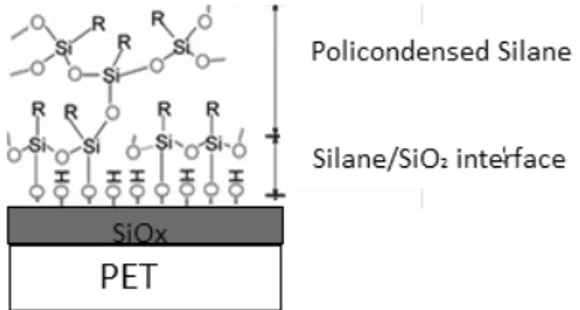
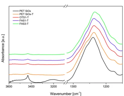
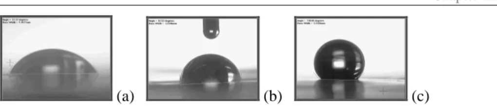
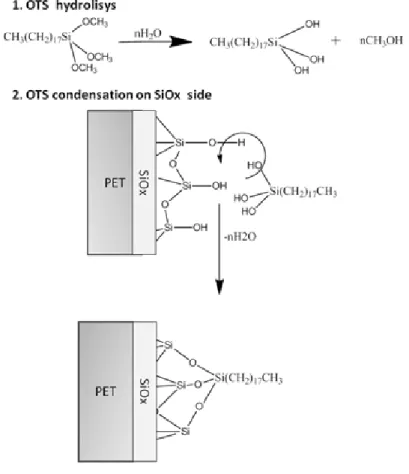
hydroxylated silane. ... 30 Figure III.6 Schematic view of the policondensation product of silanes on a PET-SiOx substrate ... 31 Figure III.7 ATR-FTIR spectra of PET-SiOx (uncoated and only dipped in toluene without reagent), OTS coated and FAS coated samples... 32 Figure III.8 Pictures of water CA measurements on uncoated PET-SiOx (a), OTS1-T (b) and FAS1-T (c) samples. ... 34
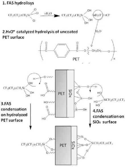
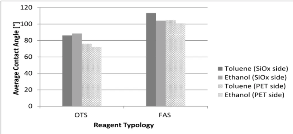
Figure III.9 Effect of the reagent typology (FAS/OTS) and of the reagent (FAS) concentration in toluene on the average contact angle measured on PET and on SiOx surfaces before and after the deposition. ... 35 Figure III.10 Hypothesis of reaction scheme for the OTS condensation. ... 36 Figure III.11 Hypothesis of reaction scheme for the FAS condensation. ... 37 Figure III. 13 AFM images with scan area 5 µm x 5 µm of a) PET-SiOx and b) FAS1-T samples ... 39 Figure III.14 Effect of the solvent (toluene/ethanol) selection on the average contact angle after deposition with OTS and FAS (1%v:v). ... 41 Table III.5 OTR for uncoated and coated PET-SiOx samples (OTS 1% in ethanol, FAS 1% in ethanol, FAS 3% in toluene). ... 42 Figure III.15 Oxygen Permeability in function of temperature for uncoated and coated PET-SiOx samples ... 44 Figure III.16 Radar chart of samples: PET-SiOx, OTS1-E, FAS1-E, FAS3-T: transparency-oxygen barrier-water barrier... 45 Figure III.17 Static water CA for ETFESiOx uncoated and coated with FAS SAM (average values calculated on the SiOx surface). ... 47 Figure III.18 % Transmittance in the UV-visible range for ETFE-SiOx uncoated and coated with FAS (1% v:v in toluene). ... 48 Figure III.19 CA average values measured during the accelerate ageing test with cyclic dipping in varying pH solutions for uncoated, OTS coated and FAS coated PETSiOx samples. ... 50 Figure III.20 CA average values measured during the accelerate ageing test with cyclic dipping in varying pH solutions for uncoated, and FAS coated ETFE-SiOx samples. ... 51 Figure III.21 CA average values measured during the accelerate ageing test with cyclic dipping in varying pH solutions for uncoated ETFE-SiOx on ETFE and SiOx sides. ... 52 Figure III.22 Average CA values in function of time during the damp heat accelerate ageing test on uncoated, FAS coated and OTS coated PETSiOx samples. ... 53 Figure III.23 Average CA values in function of time during the damp heat accelerate ageing test on uncoated and FAS coated ETFE-SiOx samples. .. 54 Figure III.24 - Average CA values in function of time during the UV exposure Accelerate Aging Test on uncoated, FAS coated and OTS coated PETSiOx samples. ... 55 Figure IV.1 Schematic representation of a Poliprotect APB pellet, with the internal phase of Ultramid® X17 copolyamide and the external phase of PET and a cobalt salt. ... 58 Fig. IV.2 Extrusion of the Active PET Film with the lab-scale extruder (THERMOPLASTICS Tokyo-Japan) ... 59 Figure IV.3 DSC thermograms of Poliprotect, Novapet, and P60. ... 62
Figure IV.4 Percent Transmittance of Novapet, P60 and Poliprotect in the UV-Visible range. ... 64 Figure IV.5 Effect of damp-heat ageing on the UV-Vis spectra of
Poliprotect (a), Novapet (b) and P60 (c) films at different ageing times. .... 66 Figure IV.6 Absorption oxygen kinetics at 25°C for Poliprotect samples in the following test conditions: dry surface and wet surface. ... 67 FIGURE IV.8. Scheme of the multilayer structure for the solar cell barrier encapsulant ... 71 Figure IV.9 % Transmittance in the UV-Visible range of samples: PET-SiOx and PET-PET-SiOx + Poliprotect. ... 72 Figure V.1 Oxygen Transmission Rate in function of the number of layers for the multilayer samples of PET-SiOx. ... 76 Figure V.2 Percent transmittance of multilayer coatings of PETSiOx and ETFESiOx ... 77 Figure V.3 Organic Solar Cells in the Glove Box ... 79 Figure V.4 Organic Solar cells encapsulated with different multilayer structures ... 80 Figure V.5 I-V measurement for encapsulated solar cell exposed to solar simulator ... 80 Figure V.6 Percent Power Conversion Efficiency of solar cells encapsulated with flexible coatings and glass in function of the time. ... 82
L
IST OF
T
ABLES
Table III.1 pH variation in function of the accelerate ageing time. ... 28
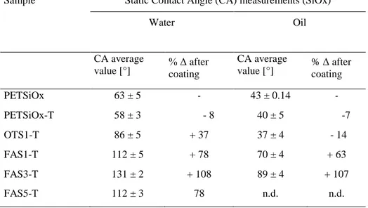
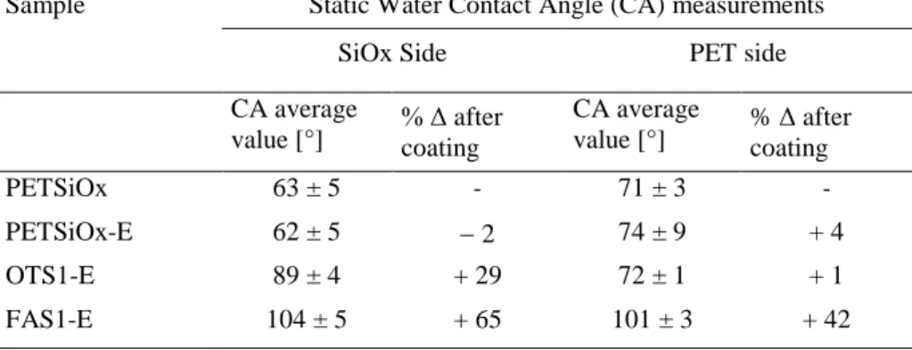
Table III.2 CA average values on SiOx and PET sides, for uncoated, OTS coated and FAS coated samples (toluene) ... 33
Table III.3 Arithmetic average roughness (Ra) and root-mean square roughness (Rq) for uncoated, OTS (1%) coated and FAS (1%) coated samples of PETSiOx. Scan area 5 µm x 5 µm. ... 39
Table III.4 CA average values on SiOx and PET sides, for uncoated, OTS coated and FAS coated samples in ethanol ... 40
Table III.6 Activation Energy for uncoated and coated samples. ... 43
Energy for uncoated and coated samples. ... 43
Table III.7 Percent crystallinity for uncoated and coated samples ... 43
Table III.8 Comparison analysis of obtained results: Present Study vs Related Works... 46
Table III.9 CA average values for uncoated and coated ETFESiOx (for both sides) ... 47
Table III.10 OTR for ETFE, ETFE-SiOx samples coated and uncoated (FAS 1% v:v in toluene). ... 49
Table III.11 Permeability for ETFE-SiOx samples coated and uncoated (FAS 1% v:v in toluene). ... 49
Table III.12 Average CA before and after the damp heat accelerate ageing test for samples PETSiOx, FAS 3T and OTS 1 E. ... 52
Table IV.1 Humidity and temperature conditions used for the oxygen absorption measurements ... 60
Table IV.2 Thermal Parameters evaluated in the DSC scans for the produced films of Novapet, P60 and Poliprotect. ... 62
Table IV.3 Oxygen Barrier Properties of Poliprotect and Novapet at 23°C: diffusion coefficient D, sorption coefficient S, permeability P and gas transmission rate GTR. ... 68
Table IV.4 Constant of first-order kinetic equation, scavenging capacity and exhaustion time for Poliprotect films with wet surface, at 25°C. ... 69
Table IV.5 Constants of first-order kinetic equation for Poliprotect films immersed in water, at 25°C, 35°C and 45°C. ... 71
Table V.1 Composition and identification codes of multilayer and single layer samples. ... 74
Table V.2 Oxygen Transmission Rate of single layer and multilayer coatings ... 75 Table V. 3 Percent Power Conversion Efficiency of PV devices coated with
flexible barrier coating compared to the glass coated reference sample (average values). ... 81
Abstract
The economic viability of photovoltaic (PV) devices is strongly dependent upon equipment cost and durability. During their usage, these devices are exposed to several atmospheric degradation agents and thus they need to be protected by coatings and encapsulants. However, even such coatings and encapsulants can degrade over time due to weather conditions, leading to potential efficiency loss and damage of the photovoltaic devices.
Nowadays, the following main properties are basically required for solar cells coating materials to ensure PV devices durability: UV, oxygen and water barrier; thermal stability, transparency, anti-reflectance, anti-soiling, flexibility, affordable cost, electrical isolation.
Therefore, in order to maintain a high efficiency during their lifetime solar cells require coating materials with several functions that are usually achieved with multilayer coatings, in which one or more layer have a specific functionality, such as gas and moisture barrier, liquid barrier and self-cleaning properties. However, a higher number of layers normally increases the cost and reduces the coating transparency and flexibility. A reduction of the number of layers would lower costs and also help to maintain a high transparency and flexibility.
This study was focused to the development of novel flexible and transparent materials able to integrate into a single layer both liquid and gas barrier functionalities by means of simple and effective single step process carried out at room temperature, specifically applied to standard coating bilayers for PV cells. To this aim, a Self Assembly of Monolayers of alkylsilanes and fluoroalkylsilanes was chemisorbed on the silica surface of a PV standard coating bilayers for solar cells such as PET-SiOx and ETFE-SiOx. The so obtained nanocoated films showed high hydrophobic characteristics with average contact angle higher than 130° for the coated PET-SiOx substrate, and a significant improvement of the oxygen barrier properties, reducing the Oxygen Transmission Rate to 1/3 if compared to that of the uncoated film.
Accelerate Ageing tests were performed in order to verify the chemical resistance of the nanocoated materials by simulating the degradation effect of both acidic and basic rains, damp heat, UV exposure. The measured contact angle values showed that after an initial slight reduction of the IX
contact angle value, a constant hydrophobic value was maintained for the samples coated with the SAM of fluoroalkylsilanes, even after 1000 hours of very drastic test conditions.
Therefore, the above nanocoated materials were compared to several multilayer structures that were laminated with uncoated PET-SiOx and ETFSiOx. It was found that the barrier properties of the nanocoated PETSiOx layer are higher than those of 2 PET-SiOx layers, thus confirming that the so improved barrier coating materials allow a reduction in the number of the necessary protective layers for the PV devices. Finally, these multilayer structures with different number of layers and compositions were applied to organic solar cells at lab scale in order to assess their effectiveness in preserving the PV devices efficiency.
Preliminary data have showed that the multilayer structure that include the nanocoated multi-barrier layer are more effective in protecting the solar cells than the other multilayer structures and that the efficiency values of the organic solar cells coated with our flexible multilayer after more than 70 days are comparable with those of solar cells encapsulated with glass.
Furthermore, another approach was pursued in this study in order to enhance the protective action of the passive barrier with the addition of an active barrier coating, able to continuously adapt its protective action according to the intensity of the environmental degradation phenomena. The driving idea is that of including in suitable polymer substrate specific oxygen absorbers, which are activated by meteorological phenomena (diurnal temperature variation, rain, etc.). To this aim active PET films were produced including an oxidizable phase that is activated by liquid water. The preliminary characterization results showed that these active barrier layers are suitable for coating photovoltaic cells, since their absorption kinetics is slow, they show an acceptable transparency and are proven to be easily processable.
Further research is still needed in order to study the effect of our passive and active barrier materials on the durability of the organic PV devices, as well as to optimize the multilayer structure design and the encapsulation process. The preliminary data on the active barrier layers are encouraging and represent a starting point for further study activities.
Chapter I
Durability issues for
photovoltaic devices
I.1 Introduction
Photovoltaics1 (PV) is a key technology option to realise the shift to a decarbonised energy supply. The solar resources in Europe and world-wide are abundant and cannot be monopolised by one country. Furthermore, photovoltaics and other renewable energies are the only ones to offer a reduction of prices, rather than an increase in the future.
From 2008 to second quarter of 2013, residential PV electricity system prices have decreased by almost 60% in the most competitive markets, and in some markets, the cost of PV-generated electricity is already cheaper than residential electricity retail prices. It is interesting to note that module prices decreased even more, by over 80%, during the same period and now represent less than 40% of the costs of a PV system. Due to falling PV system prices and increasing electricity prices, the number of such markets is steadily increasing. The consequences of the nuclear accident which took place in Fukujima in March 2011, was a shift in energy investments toward more renewables and photovoltaic systems. In 2012, solar energy attracted 57.7% of all new renewable energy investments or USD 137.7 billion (EUR 105.9 billion).
After the world-wide photovoltaic market more than doubled in 2010, the market grew again by almost 30% in 2011. In 2012, PV industry production increased again but more modestly than previous years, increasing by around 10% and reaching a worldwide production volume of about 38.5 GWp of photovoltaic modules. The PV sector is still a growing sector in spite of the financial crisis. The compound annual growth rate over the last decade was
1
Source: European Commission - Joint Research Centre - Institute for Energy and Transport. PV Status Report 2013.
about 55%, which makes photovoltaics one of the fastest growing industries at present.
There are two leading manufactured solar photovoltaic technologies in commercial use today: crystalline silicon PV and thin film PV. The vast majority of solar module demand comes from crystalline silicon (80%) with thin-film making up the balance. Since 2008, thin film has gained ground on crystalline silicon largely due to the higher manufacturing costs associated with crystalline silicon PV. Thin-film PV is the fastest growing sector of the solar cell manufacturing industry.
Thin-film cells are manufactured by applying very thin layers of semiconductor material to inexpensive materials such as glass, plastic or metal. Thin-film semiconductors absorb light more easily than c-Si, therefore requiring less semiconductor material, making them far less expensive than crystalline silicon modules. There are three main typologies of thin-film PV modules presently:
• CdTe or Cadmium Telluride thin-film, • a-Si or Amorphous Silicon thin-film,
• CIGS or Copper Indium Gallium Selenide thin-film.
Organic photovoltaic devices (OPVs), employing organic conductive polymers, are also to be mentioned for their potential to become a low-cost alternative to solid-state solar cells. Research into OPVs is rapidly growing worldwide because it offers a route to low temperature, inexpensive processing of lightweight, flexible solar cells that can be mass manufactured cheaply.
I.2 Durability of photovoltaic devices
Increasing the durability of photovoltaic (PV) plants at an acceptable cost is becoming one of the most challenging issue to foster the diffusion of PV. For instance, stringent requirements for PV modules life time of at least 30 years have been delivered by the US Department of Energy. One of the most important technological factors to enhance the PV modules durability is represented by the availability of suitable coating materials with high barrier properties, flexibility, and affordable cost.
Different PV systems (c-Si, thin film, organic PV) have different modules lifetime, with the higher module lifetime corresponding to the most mature technology and the lower values to the latest technologies.
Crystalline Silicon Cells commercially available are generally guaranteed for 25-30 years, while for instance 2-3 years is the guaranteed operational lifetime for commercially available flexible CIGS solar cells and even lower lifetimes can be measured for polymer solar cells. Therefore, the barrier properties of coating materials are of a special concern for thin film PV cells, 2
which are more sensitive against the degradation effect due to atmospheric agents.
Indeed, although crystalline silicon panels are the oldest, most reliable and highly efficient PV panels in the market today, they still present durability issues that need to be tackled.
Information on PV module (wafer-based) degradation has been collected since the early 1970’s, but the work seems to be inadequately coordinated. Power degradation rates for c-Si modules between 0.7% and 9.8% in the first year and between 0.7% and 4.9% in the second year have been reported2. A recent study of Abenante et al. (2010) was carried out at the experimental station of ENEA for measuring the efficiency degradation over a 30 years period providing the following results:
- current average efficiency: 8,3% (87% of the initial value); - absolute efficiency decrease of 1,2% in 30 years;
- total relative efficiency decrease of 13%.
Figure I.1 Comparison of modules efficiency in years 2010, 2003 and 1990.
The operational module lifetime is generally defined as the period in which its power output decreases by less than 20%. What is usually referred to in photovoltaics as “reliability,” such as no more than 1% power loss per year to a maximum of 20%, is actually a durability issue.
The efficiency reduction of the PV modules is caused by several and different degradation mechanisms that will be briefly examined in the following section. One of the most important technological factor to be considered for enhancing the PV modules life time is represented by the
2
LEEETISO,CH-Testing Centre for Photovoltaic Modules, http://leee.dct.supsi.ch/PV/Results/Tested_modules.htm 3
availability of suitable encapsulant and coating materials with high barrier properties, flexibility and affordable cost.
In particular (Erler et al., 2003), modules based on thin film solar cells are significantly more sensitive against the degradation effect of the atmospheric agents than modules using crystalline Si-solar cells and the demands on encapsulation materials are much higher for thin film solar cells.
The degradation of the PV devices that leads to durability and reliability problems is caused by several factors.
The use of the words reliability and durability are not consistent throughout the literature. To avoid confusion the word durability will be used in connection with the slow, gradual, time-dependent performance loss in a PV cell, module, or system, while the term reliability will be used to describe sudden failures.
General reliability issues across all PV technologies are (Bosco, 2010): • corrosion leading to a loss of grounding,
• quick connector reliability,
• improper insulation leading to loss of grounding, • delamination,
• glass fracture, • bypass diode failure, • inverter reliability, • moisture ingress.
In addition, there are issues specific to the individual technologies, to name a few:
i. wafer silicon: light-induced cell degradation, front surface soiling, effect of glass on encapsulation performance, reduced adhesion leading to corrosion and/or delamination, busbar adhesion degradation, junction box failure;
ii. thin film silicon: electrochemical corrosion of SnO2, initial light degradation;
iii. CdTe: interlayer adhesion and delamination, electrochemical corrosion of SnO2:F, shunt hot spots at scribe lines before and after stress;
iv. CIS: interlayer adhesion, busbar mechanical adhesion and electrical, notable sensitivity of TCO to moisture, moisture ingress failure of package;
v. OPV: photolytic instability, moisture induced degradation, moisture ingress failure of package.
Another study (Quintana et al. 2002) classifies the degradation phenomena of the PV modules into five categories that ultimately drive performance loss and possibly failure. These are:
1) degradation of packaging materials, 2) loss of adhesion,
3) degradation of cell/module interconnects, 4) degradation caused by moisture intrusion, 5) degradation of the semiconductor device.
Degradation of encapsulant and packaging materials
Module package degradation occurs when the laminate package is damaged or packaging materials degrade during normal service, affecting the function and/or integrity of the module. Examples of packaging degradation include glass breakage, dielectric breakdown, bypass diode failure, encapsulant discoloration, and backsheet cracking and/or delamination. Package degradation can cause module performance failures, which can lead to system level issues like array performance failure, safety hazards, and/or failure of a supplemental function, e.g. a module functioning as a window in a BIPV application.
Loss of adhesion
Delamination is defined as the breakdown of the bonds between material layers that constitute a module laminate.
Field experience has shown that front-side delamination at the glass/encapsulant and cell/encapsulant interfaces is more common than backside delamination. Front-side delamination causes optical decoupling of materials that transmit sunlight to the cells, resulting in performance degradation. Delamination on either side interrupts efficient heat dissipation and increases the possibility of reverse-bias cell heating. Higher cell operating temperatures cause performance degradation.
Degradation of cell/module interconnects
Interconnect degradation in crystalline silicon modules occurs when the joined cell-to-ribbon or ribbon-to-ribbon area changes in structure or geometry. “Coarsening”, a change in joint structure, occurs as a result of segregation of the metals (SnPb) in the soldering alloy. Coarsening causes the formation of larger metal grains that undergo thermomechanical fatigue, enhancing the possibility of cracking at the grain boundaries and possible joint failure.
Interconnect degradation in thin-film modules is distinctively different. Observations of field-aged modules have found that a prime location for continuity failure is the point where the junction-box interconnect strap bonds to the cell frit. This is a very vulnerable solder bond that is likely to incur thermomechanical fatigue as a result of daily thermal cycling. Thin-film module scribe-line problems emerge when either the SnO2 cell isolation scribe-lines or the back metal cell isolation scribe lines do not have the 5
material completely removed. In either case, partially shunted cells are the result.
Degradation caused by moisture intrusion
Moisture permeation through the module backsheet or through edges of module laminates causes corrosion and increases leakage currents. Corrosion attacks cell metallization in crystalline silicon modules and semiconductor layers in thin-film modules, causing loss of electrical performance. Figure I.2 shows moisture-induced corrosion that caused gridline adhesion to the silicon cell to fail. Retention of moisture in module packaging materials increases material electrical conductivity. This causes increased leakage current and subsequent performance loss. Moisture intrusion has also been linked to loss of adhesional strength at bond interfaces in the module laminate. Moisture intrusion combined with damaged module packaging materials can introduce severe safety concerns in high voltage applications.
Figure I.2 Moisture induced corrosion that caused bonds between the grid
lines and the cell to fail.
Degradation of the semiconductor device
Degradation of the semi-conductor material itself can also contribute to performance loss in field-aged modules. Crystalline silicon modules now have a long track record of performance stability in the field. This stability, in part, is due to the stability of the semiconductor material (crystalline silicon) used to make the cells. Field experience has indicated that the primary causes for performance loss in these modules have been associated with mechanisms external to the cells such as solder bonds, encapsulant browning, delamination and interconnect issues. Initial light induced degradation (LID) is one of the few changes that can be attributed to the c-Si semiconductor device. The LID effect is limited to the first few hours of outdoor module exposure and results in a 1-5% loss in short-circuit current (Saitoh et al. 2000).
It is also to be mentioned the Czochralski silicon (Cz-Si) specific lifetime degradation, that is induced by carrier injection or illumination. After an 6
illumination of about 12 h AM3 1.5 (depending on the doping level), the lifetime is reduced exponentially to a (fortunately) stable end value. This lifetime degradation can be completely reversed by an anneal step of around 200 8C in room ambient. This phenomenon is very similar to the Staebler– Wronski effect in amorphous solar cells and was related to the presence of interstitial oxygen in the Cz-Si grown crystals (Goetzberger et al. 2003).
Another form of degradation in crystalline cells is a result of chemically assisted diffusion of cell dopant (phosphorous) to the cell surface. High concentrations of phosphorous, along with sodium migrating from soda lime glass superstrates to the cell surface, have always correlated to low adhesional strength at the cell/encapsulant interface. Furthermore, it has been reported that loss of adhesional strength is exacerbated by exposure to high humidity environments (Dhere 2000, Dhere 2001).
Degradation and/or stabilization of a-Si modules have been the subject of many studies but there seems to be a lack of complete understanding of the mechanisms and environmental influences that cause performance degradation, such as the initial light induced degradation (Staebler–Wronski effect) (King et al. 2000, Wronski, 2000).
Recent data from fielded CdTe and CIS applications suggests higher than expected performance degradation and potential for system level failures.
Damp heat studies (Olsen et al.) of CIGSS and CdTe cells have been conducted by subjecting cells and min-modules to an environment 60C/90%RH, showing that both CIGSS and CdTe cells degrade rapidly under 60C/90%RH unless they are protected with a barrier coating.
3 AM: Air Mass
7
Figure I.3 Efficiency versus time for three encapsulated min-modules and
one uncoated CIGSS circuit.
As for the organic PV devices, the degradation mechanisms of conjugated polymer materials used in these cells were also studied (Krebs and Norrman 2007). It was found that molecular oxygen diffuses into the device causing oxygen-containing species to be generated throughout the active layers.
Conjugated (Lungenschmieda et al. 2006) polymers are known to be rather unstable in air, being particularly susceptible to photodegradation induced by oxygen and moisture. Especially poly(p-phenylene vinylene) (PPV) and its derivatives are susceptible to degradation in atmosphere. The mechanism involves the binding of oxygen atoms to vinyl bonds, which breaks the conjugation and leads to the formation of carbonyl groups. Besides, it has been reported that water can affect the interface between the metallic contact and organic semiconductors by an electrochemical process that causes delamination of the electrode.
I.3 Degradation of encapsulant and coating materials
The wafer-based PV devices are generally encapsulated with EVA with a front layer of glass and a backsheet of tedlar. Sometimes, for particular needs (such as BIPV), transparent PV modules are glass-EVA-glass laminated. Recently, also silicone has been studied and proposed as an alternative to the EVA encapsulants. An example of commercial product is the SilTRUST* transparent silicone encapsulant material presented from Momentive Performance Materials Inc at the Polymers in Photovoltaics 2012 forum in Cologne.
However, in practice glass is still the only frontsheet material used for wafer-based PV modules.
Thin film solar cells are generally encapsulated with glass or multilayer flexible films comprising different layers and also including high barrier layer(s). For instance, CIGS modules are encapsulated using vacuum lamination or roll to roll lamination of the gas barrier material (glass or barrier foil) with encapsulating materials as EVA, silicons or other encapsulant. Lateral permeation from the edge is difficult to control due to poor intrinsic gas barrier properties of encapsulating polymers and delamination process occurring with aging.
In general, the coating and encapsulant materials degradation can be of the following types: thermal, oxidative, photoinduced, mechanochemical, chemical, metal-catalyzed, and combinations of these (Czanderna and Pern 1996, Quintana et al. 2002).
Furthermore, also soil (e.g. dust, limestone, etc.) deposition (Hammond et al. 1997) on the frontsheet surface can reduce the coating transparency and, as a consequence, the efficiency of PV devices.
In general, three main degradation causes can be identified for the encapsulant materials:
• UV radiations • O2
• H2O.
Ultraviolet irradiation (Czanderna and Pern 1996) of polymers can bring about two primary types of reactions, chain scission and crosslinking. With sufficient exposure to either long-term moderate irradiation or short-term intensive irradiation, both these reactions will eventually result in changes in the mechanical properties of the polymers.
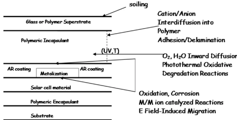
Fig. I.4 Schematic cross-section of an encapsulated PV cell and relevant
reactions/processes that may reduce the cell performance and/or service lifetime.
Chain scission reactions lead to a reduction in the molecular weight of the polymer, eventually causing a loss in mechanical properties, since the ultimate mechanical properties such as elongation to break are usually very sensitive to a reduction in molecular weight.
Crosslinking reactions increase the stiffness of the polymer but also result in a decrease in the elongation to break. High levels of crosslinking will lead to enbrittlement of the polymer, which is particularly important for rubbery polymers used as adhesive or sealants. Crosslinking of rubbery polymers can decrease the ability of a polymer to recover from cyclic stress.
The permeability of polymers is influenced by both the mobility of the polymer chains and the strength of the interaction between the polymer and penetrant. The mobility of the polymer chains can be affected by prolonged exposure to environmental stresses.
The rate of permeation of gases through glassy polymers increases with increasing temperature, and is less sensitive to changes in temperature through rubbery polymers. Migration of plasticizer and stabilizers through glassy polymers is accelerated by increases in temperature. For hydrophilic polymers, an increase in the relative humidity can result in an increase in the permeability of both water vapor and other permeant gases.
Chain scission or crosslinking caused by UV irradiation can have a substantial influence on permeability. Chain scission increases the free 10
volume of the polymer system, which can lead to an increase in permeability. Crosslinking restricts the mobility of the polymer chains, which generally leads to a decrease in permeability.
Chapter II
Barrier materials for enhancing
the durability of solar cells
II.1 Introduction
Nowadays, the following main properties are basically required for solar cells coating materials to ensure PV devices durability: UV, oxygen and water barrier (Morlier et al. 2013); thermal stability, transparency, anti-reflectance (Lu et al. 2011), anti-soiling, flexibility, affordable cost, electrical isolation (Frach et al. 2008). Some of these properties are competitive ones. For instance, high barrier properties may be achieved by increasing the number of coating layers (Logothetidis et al. 2010). However, a higher number of layers normally increases the cost and reduces the coating transparency and flexibility (Erler et al. 2003).
In order to maintain a high efficiency during their lifetime solar cells require coating materials with several functions that are usually achieved with multilayer coatings (Vaško et al. 2009, Visser 2008), in which one or more layer have a specific functionality, such as gas and moisture barrier (Jorgensen et al. 2006, Langereis et al. 2006), liquid barrier and self-cleaning properties (Karunakaran et al. 2011). A reduction of the number of layers would lower costs and also help to maintain a high transparency and flexibility.
II.2 Coating Materials with gas barrier properties
The ability of oxygen and moisture to cross an encapsulating membrane is expressed by the oxygen transmission rate (OTR) and the water vapor transmission rate (WVTR), respectively. It has been demonstrated and is generally accepted (Lungenschmied et al. 2006) that the lifetime of thin film
and organic PV cells require 10-4 ~ 10-3 g m-2 d-1 values of WVTR and 10-3 cm3 m-2d-1 atm-1 values of OTR (Fig. II.1) .
Figure II.1 Water vapor transmission rate (WVTR) versus oxygen
transmission rate (OTR) for commercial polymers, encapsulations required for food packaging and for organic electronics purposes.
Thin film barrier coatings against permeation of gases and vapors deposited onto flexible polymer substrates have been intensively studied (Lungenschmied et al. 2006) for applications in food and pharmaceutical packaging, where improving the barrier capabilities of the bare plastic films by one to three orders of magnitude is usually considered sufficient.
The barrier protective films that are currently studied for the PV applications are generally composed of one or more layers of polymer substrate with an inorganic coating. The inorganic coating is generally consisting of SiOx or AlOx while the polymer substrate may be EVA, ETFE, PET or PEN. The inorganic coating is typically realised by PECVD or Electon Beam Evaporation, although, as already said before, more recent techniques like the ALD seem to produce higher quality of the coating (Langereis et al. 2006).
Because the moisture permeation properties of a single layer barrier are eventually limited by the defect density of the layer, the deposition of multilayer structures is expected to be the path towards the WVTR requirements mentioned above. Of course, the multilayer structures become most effective when the individual layers themselves have excellent permeation properties.
An example of a commercial multilayer material with very good barrier properties (WVTR ~10-6 g/m2d) is the “BARIX” film of Vitex. It is composed of 4 bilayers polymer/inorganic. The Multilayer effectiveness is 14
based on two main factors: 1) redundancy and 2) tortuosity. In fact, the barrier response of the inorganic coatings is defined by their lattice disorder that results from the deposition process. This disorder has the form of macro- and nano-defects (pinholes and micro-cracks) that are formed during the growth process of the inorganic thin films by physical vapour deposition methods such as sputtering and evaporation.
These defects provide easy pathways for moisture and oxygen permeation, thus limiting the barrier performance of the inorganic film/polymer substrate system (Logothetidis et al. 2010). Therefore, the barrier mechanism is essentially due to a lag time effect4. However, the BARIX Film presents the disadvantage of a high cost, as a consequence of its complex production process that foresees several steps.
Other alternative approaches that have been developed for the gas barrier coating are:
• Hybrid polymer ORMOCER® coating: Sol-gel based processing of hybrid polymers (ORMOCER®s) with inorganic and organic structural units is used for functionalized coatings on a variety of substrates (ceramics, metals, polymers, etc). At temperatures below 150 °C the formation of both inorganic and organic network structures is possible. Functional organic groups bound to the inorganic network are used to modify surface properties. ORMOCER®-lacquers can be processed by all conventional coating techniques (dipping, spraying, spin on etc.) and cured by thermal or radiation energy. The dense inorganic network of ORMOCER®s combined with organic crosslinking and the possibility to control the polarity of the matrix, makes them useful as barrier layers for gases, vapors and ions (Haas et al. 1999). The introduction of functionalized alkoxides into thermally curable ORMOCER® systems can modify the coating surfaces. Hydrophilic/-phobic and oleophilic/-phobic can be achieved by the incorporation of appropriate functional groups. The wetting angles for water on fluorosilane modified ORMOCER® is > 110°.
• Use of nanoparticles included in the inorganic layers: this method allows to reduce the total number of layers. Several research works have investigated the use of nanoparticles in organic or inorganic layers. The (
Ravichandran et al. 2008)
use of a novel Saran (a co-polymer of vinylidene chloride and acrylonitrile) based co-polymer nanotube composite, which shows high transparency in the visible region, good barrier properties and thermal stability, has been studied for the encapsulation of OPV devices. Moreover, the inclusion of silicon dioxide particles has been studied in order to4 Source: Vitex Systems
15
further improve the barrier properties of the hybrid polymers. This method offers a possibility to increase the inorganic network degree of the ORMOCER® based polymers and thus should lead to a reduction of the OTR and WVTR values (Logothetidis et al. 2010). A commercial product that uses the nanoparticle in organic layers, in order to “seal” the defects of the inorganic layers. This approach allows to obtain a WVTR = 10-6 g.m-2.d-1 and also of 10-4. The nanoparticle increase surface area so that the residual moisture or oxygen can be effectively adsorbed and reacted with nanoparticles • Atomic Layer Deposition (ALD). The ALD technique has been
studied to produce gas-diffusion barriers on polymers, and water vapour transmission rate of the order of <0.5*10-4 g m-2d-1 was reported for less than 15-nm thick Al2O3 depositions on polymers (Garcia et al. 2010a). Direct encapsulation of CIGS solar cells by ALD has also been shown to provide excellent stability in damp-heat conditions (Garcia et al. 2010b). However, since thin-film solar PV modules are rather protected by lamination than direct encapsulation, means to produce ALD ultra barriers by roll-to-roll process have been studied (Maydannik et al. 2011). Although ALD allows obtaining very dense layers with improved barrier properties, challenges still remain in implementing ALD for solar cell barriers. Robustness of the process towards cleanliness and surface chemistry of incoming substrates must be improved by pre-treatment processes. For example, planarization of the solar cell surface prior to the ALD process may offset a potential particle issue and provide chemically uniform surface with good adhesion to the thin-film barrier layer.
Concerning the commercial products, it is to be considered the current emergence on the market of new barrier films with medium barrier properties (Mitsubishi X Barrier, 3M Ultrabarrier solar film, Toppan, Amcor..etc). Other commercial products recently developed is the ENLIGHTTM Polyolefin Back Encapsulant Composite Films, a new polyolefin-based technology introduced by Dow Chemical that uses patent-pending technology to create a single structure that provides “2-in-1” functionality, serving as both the back encapsulant and backsheet for solar panels. However, it remains opaque and cannot be used as a front sheet.
A recent patent (Ichimura et al. 2012) that may be mentioned here to conclude this sub-section concerns a solar-cell back-side protective sheet for protecting solar modules from adverse weather conditions that could damage electrical insulation. The backsheet is provided with: a base film comprising at least one layer; a vapor-deposited film that is formed on the surface of the 16
base film and exhibits good barrier performance; and a coating layer that comprises at least one layer and is formed on the surface of the vapor-deposited film opposite the base film. Said coating layer is a ternary-copolymer layer obtained by curing a liquid film that has a resin component comprising a metal alkoxide with a reactive functional group (Y); an acrylic monomer with a reactive functional group (X) that reacts with the aforementioned reactive functional group (Y); and an acrylic monomer that does not have said reactive functional group (X).The proposed structures maintained good water vapour barrier properties (0,01 g/m2 in 24 hours for a multilayered structure with a 75 µm PET layer, 5 µm of alkoxysilane adhesive, 12 µm of PET with silicon-dioxide vapour-deposited film, sandwiched between two layers of a 20 µm ternary copolymer) also after weathering tests.
II.3 Coating materials with liquid barrier properties
There are several methods for obtaining hydrophobic or superhydrophobic surfaces. In general, these methods try to imitate the hydrophobic mechanism which can be observed on natural objects such as the lotus leaf (the so called “lotus effect”).
One of these methods for obtaining hydrophobic surfaces is represented by the Self Assembly of Monolayers (SAM) using precursor molecules with high hydrophobic properties in order to create protective nano-coatings. In particular, this method was applied by means of alkylsilanes and (fluoro)alkylsilanes deposition on glass substrates (Altavilla et al. 2011) and successfully allowed to obtain hydrophobic surfaces. Other methods that are employed to achieve superhydrophobicity are based on the introduction of a two-scale roughness (micrometric and nanometric scales), together with chemical functionalization.
An example is provided by the superhydrophobic and low light reflectivity silicon surfaces prepared by (Au)-assisted etching to form nanoscale roughness and thereby form hierarchical structures by metal-assisted etching of micron-size pyramid textured surfaces (Xiu et al. 2008), followed by surface fluorination with perfluorooctyltrichlorosilane (PFOS), and by a heat treatment at 150 ° C to complete the hydrophobic surface modification.
Moreover, it is worth mentioning the use of nanoparticles (NPs) that has been imposing as an effective way to control the surface nanoroughness. A simple approach was recently demonstrated by dip-coating a single layer of 60 nm SiO2 NPs onto an amine-terminated self-assembled monolayer (SAM)-coated glass/silicon oxide substrate, followed by perfluorosilane deposition (Ling et al. 2009).
Another method (Karunakaran et al. 2011), that was proposed for creating transparent and superhydrophobic surface suitable for solar cells 17
applications, is based on the coassembly of amine-functionalized silica NPs (McConnell et al. 2009) of two different sizes (100 and 20 nm) followed by perfluorosilane deposition. This study (Karunakaran et al. 2011) allows to obtain very high hydrophobic properties and is applied on different substrates (glass, silicon, polyester materials). However, it is a multi-step process involving plasma treatment steps of the substrate surfaces as well as high temperature steps (>150 °C).
Although the above described approaches report very interesting results in terms of achieved hydrophobicity on substrates potentially applicable to the solar cells sector, they are likely to turn out to be expensive and difficult to be implemented at industrial level because they are multi-step processes, including complex and high temperature steps.
There is the need of a simple and single step process for obtaining hydrophobic surfaces suitable for the solar cells coating materials in order to improve the solar cells protection at affordable costs.
II.4 Coating Materials with active barrier properties
The passive barrier layers can be further improved by the combination with active oxygen barrier layers which have been developed for the food packaging industry (Amberg-Schwab et al. 2006). This approach makes these multilayer laminates promising candidates for special applications in the food packaging industry as well as for sophisticated applications in technical areas such as the encapsulation of sensitive organic devices like solar cells, organic light emitting diodes, or polymer electronic systems.
There are only few theoretical studies considering the use of suitable oxygen scavengers to be included in polymer barrier layers for solar cells.
An interesting research work (Amberg-Schwab et al. 2006) is based on the functional principle of the newly developed oxygen scavenger system, based on a photo-initiated, metal catalyzed oxidation of a cyclo-olefin bonded chemically to a silicate backbone. This concept permits the activation of the scavenging process by UV light and prevents the formation of low-molecular oxidation products which may decrease the quality of the packaged goods or may be toxic. The oxygen scavengers studied in this work are selected on the basis of two related patents of Chevron Chemical Company (Ching et al. WO99/48963) and Cryovac Inc (Matthews and Depree 2001) concerning the “Oxygen scavengers with reduced oxidation products for use in plastic films”.
However, the PV cells have different technical requirements with respect to the food products, since the oxygen scavenging activity should be extended during the time, their transparency is to be maintained and the development of toxic by-products inside the solar module is not a problem so relevant as for the food industry.
Furthermore, SAES Getters5 recently introduced some products with active barrier properties for water vapor such as: B-dry (edge sealant), DryPaste and AqvaDry (getter pastes), eDry (printable scavenger) and ZetaFill (printable active scavenger for OPV). Nevertheless, these products need to be stored in nitrogen atmosphere and at low temperature before they are applied and also have some drawbacks concerning the optical properties
.
II.5 Aim of the study and structure of the PhD work
This Ph.D study aims to develop new passive and active barrier materials for coating flexible solar cells in order to extend their lifetime. The research objective is to study a simple method able to enhance the barrier properties against the atmospheric degradation agents of the flexible coating layers usually employed for coating solar cells. The final aim is to guarantee a higher protection degree with a lower number of coating layers, so reducing the material costs and increasing at the same time the flexibility and the transparency.
The research approach was focused on the study and development of novel flexible and transparent nanocoating, able to integrate into a single layer both liquid and gas barrier functionalities.
A simple and effective single step process carried out at room temperature was studied to apply a flexible passive multi-barrier coating with improved performance to standard coating bilayers usually employed for PV cells. The improved barrier properties against oxygen and liquid atmospheric agents are expected to guarantee higher lifetime for PV modules with higher flexibility and transparency and at lower costs.
In fact, although the related works (Karunakaran et al. 2011, Xiu et al. 2008, Ling et al. 2009, McConnell et al 2009, Teshima et al. 2003) report very interesting results in terms of achieved hydrophobicity on substrates potentially applicable to the solar cells sector, they are likely to turn out to be expensive and difficult to be implemented at an industrial level because they are based on multi-step processes, including plasma treatment and high temperature steps.
Thus, the novelty of the proposed approach consists in the study of a single step and room temperature process. Furthermore, both gas and liquid barrier properties of the modified surfaces were not investigated in the literature except for the study of Teshima et al. (2003), to our knowledge. However, the optical transparency properties were not analyzed in that study and the obtained performances in terms of gas (O2) and liquid barrier improvement were too moderate to be considered of interest for PV applications.
5 www.saesgetters.com
19
Subsequently, accelerate ageing tests were performed on the developed flexible multibarrier materials in order to assess the resistance of the barrier nanocoating in different conditions (damp heat, dipping cycles in varying pH solutions, UV exposure).
Finally, the encapsulation of organic solar cells with several flexible multilayer structures previously characterized was carried out at lab scale in order to assess the capability of the developed flexible coating to preserve the efficiency of solar cells
In particular, this final phase of the study was aimed to compare the stability obtainable by flexible coatings with the glass and to investigate the effect of the novel passive multi-barrier coating previously developed in comparison with the standard flexible materials. This research activity is still in progress and at date only preliminary data were obtained.
Another approach that was followed during the PhD study was aimed to develop an active barrier coating for solar cells able to continuously adapt its protective action according to the intensity of the environmental degradation phenomena. The driving idea is that of including in suitable and transparent polymer substrate specific oxygen absorbers, which are activated by meteorological phenomena (diurnal temperature variation, rain, etc.). This system may offer an active and dynamic protection able to react to the environmental changes. There are only few theoretical studies considering the use of suitable oxygen scavengers to be included in polymer barrier layers for solar cells, (Amberg-Schwab et al. 2006) essentially based on the use of oxygen scavenger systems activated by UV radiation.
Furthermore, there are some commercial products that were recently introduced by SAES Getters6 with active barrier properties for water vapor. However, these products need to be stored in nitrogen atmosphere and at low temperature before they are applied and also have some drawbacks concerning the optical properties.
The research activity on the active barrier layers provided some preliminary but encouraging results that represent a basis for future study in this field.
The coating materials studied and developed with the above approaches are thought to be included in a multilayer structure where they can act synergically in order to guarantee a better protection to the flexible solar cell, like shown, for instance, in fig. II.2.
6 www.saesgetters.com
20
Figure II.2 Schematic representation of a multilayer structure hypothesis
The experimental work that was performed for pursuing the envisaged objectives of studying new flexible barrier materials to enhance the solar cells durability is reported in the following chapters. Four main phases may be identified in the research workflow:
• study and development of flexible multi-barrier coating materials, included in chapter III
• study and development of active barrier materials, reported in chapter IV
• development and characterization of multilayer coatings, described in chapter V
• encapsulation of organic solar cells with the developed materials in order to assess their effectiveness in improving the solar cells durability, also reported in chapter V.
Liquid barrier layer
Gas Passive barrier layer Gas Active barrier layer
Solar cell
Chapter III
Passive Multi-barrier layers
III.1 Introduction
This chapter includes the description of the study of a multi-barrier nanocoating, for enhancing the photovoltaic devices durability. In particular, the nanocoating integrates into a single layer more barrier functionalities: oxygen barrier properties, hydrophobic and oleophobic properties.
This nanocoating is deposited on standard solar cells coating organic-inorganic bilayers by applying the Self Assembly of Monolayers (SAM) technique, which represents a powerful and versatile strategy to create substrates with controlled molecular-level physicochemical characteristics (Lee et al. 2007).
Self assembled monolayers are ordered molecular assemblies that are formed spontaneously by the adsorption of a surfactant with a specific affinity of its endgroup to a substrate (Fig. III.1).
In particular a SAM structure of (fluoro)alkylsilanes chemisorbed on the inorganic layer of a inorganic-organic substrate (e.g. PET-SiOx) is expected to add hydrophobic and oleophobic functionalities to the film surface and also, hopefully, to increase the barrier properties of the substrate.
Considering that inorganic/organic bilayers such as PET-SiOx are the basic units which compose the multilayer barrier film used for protecting PV cells, a reduction of the number of bilayers that is necessary to ensure the solar cells durability may be achieved with this approach as a consequence of the improved barrier of the single bilayers.
As already discussed in Chapter II, the approach is novel in comparison with the related works, since it consists in the study of a single step room temperature process instead of multistep and complex processes. Furthermore, to our knowledge, both gas and liquid barrier properties of the modified surfaces were not investigated in the literature except for the study of Teshima at. al. However, the optical transparency properties were not analyzed in that study and the obtained performancesin terms of gas (O2) and
liquid barrier improvement were too moderate to be considered of interest for PV applications (see tab. III.8 for a comparison analysis of the present approach and the related works).
substrate
Figure III.1 Schematic exemplification of a SAM
III.2 Experimental Details
III.2.1 Materials
The following reagents were used: 1) octadecyltrimethoxysilane (OTS) provided by Aldrich and 2) 1H,1H,2H,2H-per-fluorodecyltrichlorosilane (FAS), provided by Alfa Aesar.
The (fluoro)alkylsilanes deposition experiments were carried out on two kind of flexible and transparent bilayer substrates: a) PETSiOx of 12 µm thickness provided by AMCOR7 , composed of a polymer substrate (PET) with an inorganic coating (SiOx) layer of ~ 50 nm deposited with Electron Beam Evaporation, and b) ETFESiOx of 100 µm thickness provided by AMCOR , composed of a polymer substrate (ETFE) with an inorganic coating (SiOx) layer of ~ 50 nm deposited with Electron Beam Evaporation. Anhydrous toluene (distilled) and anhydrous ethanol (H2O ≤ 0.01%), provided by Sigma Aldrich were used as solvent, alternatively.
Figure III.2 Chemical structure of the octadecyltrimethoxysilane (OTS).
7 www.amcor.com
24
Figure III.3 Chemical structure of the 1H,1H,2H,2H
perfluorodecyltrichlorosilane (FAS).
III.2.2 Deposition experiments for the preparation of nanocoated
samples
The film samples of PET-SiOx and ETFE-SiOx were accurately cleaned before the deposition reaction, in order to remove all the impurities from the SiOx surface.
The cleaning procedure consisted of subsequent dipping cycles with toluene and distilled water with intermediate drying in N2 flow. The deposition experiments were performed in a glass batch reactor where the substrate was placed.
The glassware was preliminary flame dried in order to remove any trace of water vapour and subsequently a N2 atmosphere was maintained in the reactor.
The reactor was specifically designed during the PhD study in order to optimize the SAM deposition on these organic-inorganic substrate. The system was equipped with a sample holder in teflon allowing a quick and easy insertion/extraction procedure without any contact with the inorganic coating of the substrate sample, since its barrier properties are very sensitive to the mechanical abrasion effects (Fig. III.4).
OUT N2
IN N2
SUBSTRATE SAMPLE IN: a) Solvent, b) Reagent (silane)
SOLVENT
Figure III.4 Schematic view of the reactor designed and used during the
PhD study for the SAM deposition on the organic-inorganic substrates.
For the reaction experiments two solvents were used, toluene and ethanol. In a first experimental phase, silane deposition was performed by immersion of the substrate samples (surface area from 10 cm2 to 80 cm2) in 80 ml of a 1% (v:v) solution of silane (for both OTS and FAS experiments) in distilled toluene and under anhydrous conditions. Subsequently, different reagent v:v concentrations (1%, 3%, 5%), as well as a different solvent (ethanol), were used for the FAS deposition experiments.
The reaction was stopped after 12 hours and the obtained samples were then cleaned by subsequent dipping cycles with toluene and distilled water with intermediate drying in N2 flow. PETSiOx substrates were also dipped for 12 hours in the solvents without reagents, in order to investigate eventual solvent induced modifications.
Codes of the produced samples: the produced samples will be indicated
from now on in the text according to the following nomenclature: RZ-S, where: R is the reagent that can be OTS or FAS, Z is the v:v percent concentration of R in the solvent and S is the used solvent, that can be T (toluene) or E (ethanol). All the obtained samples are listed below according to the above defined nomenclature: OTS1-T, OTS1-E, FAS1-T, FAS3-T, FAS1-E, FAS3-E, FAS5-T, FAS5-E. The samples obtained by dipping the substrates in the solvents – toluene and ethanol - without reagents are indicated with PETSiOx-E and PETSiOx-T, respectively. The nanocoated sample of ETFESiOx is indicated as ETFESiOx FAS1-T.
III.2.3 Characterization of the nanocoated samples
FTIR (Fourier Transform Infrared Spectroscopy) measurements were carried out on the uncoated and coated samples in the range of 4000–650 cm using a Nexus ThermoNicolet spectrometer equipped with a SmartPerformer accessory for ATR analysis.
The hydrophobic properties of the obtained samples were assessed by means of static water contact angle measurements, performed by depositing 5 drops of distilled water of 2 µl on each side of the sample and then calculating the average values for each side.
Experimental measurements were performed with a First Ten Angstrom Analyzer System 32.0 (mod. FTA 1000) according to the standard test method ASTM D5946. The oleophobic properties were also preliminarily investigated by means of static oil contact angle measurements performed by depositing 3 drops of 2 µl of polyalphaolefinic synthetic oil PAO6 on each side of the sample and then calculating the average value for each side.
The OTR measurements were carried out with the Permeabilimeter GDP – C 165 provided by Brugger at 23°C and under oxygen flow of 80 ml/min, according to the standard ISO15165-1. Measurements at higher temperature (35 and 45°C) were also performed for studying a temperature range closer to the actual operating conditions of the PV devices.
The transparency was evaluated by measuring the UV-visible transmittance of the nanocoated surfaces from 200 nm to 800 nm with the UV-Visible Spectrophotomer λ 800 Perkin Elmer.
The surface morphology was characterized using a Nanoscope V multimode Atomic Force Microscope (Digital Instruments) and the root-mean-square roughness (Rq) values were calculated on scan areas of 5 µm x 5 µm with the Software Nanoscope Analysis of Bruker (version 1.40).
The thermal characterization was carried out with a Mettler Differential Scanning Calorimeter (DSC30), performing a dynamic 10°C/min rate heating scansion of the uncoated and nanocoated samples from -100°C to 300°C, followed by an isothermal scansion of 5 minutes at 300°C, by a subsequent cooling up to -100°C and then by a second heating up to 300°C (both at 10°C/min).
The heat of melting, ΔHm, and cold crystallization, ΔHc, were determined by integrating the areas (J/g) under the peaks.
The percent crystallinity values Xc were calculated according to the following equation:
(III.1) where ΔHm is the heat of melting, ΔHc the heat of cold crystallization and ΔHm0
is the heat of melting if the polymer was 100% crystalline, taken 27