POLITECNICO DI MILANO
Facoltà di Ingegneria Industriale e dell’Informazione
Master’s Degree in Chemical Engineering
AG2S™ T
ECHNOLOGY OPTIMIZATION:
APPLICATION
OF A
GENERALIZED
FRAMEWORK INCLUDING ROBUST
OPTIMIZER INTO ASPEN HYSYS
Supervisor
Prof. Flavio Manenti
Tutor
Ing. Andrea Bassani
Candidate
Riccardo Fossati
Matr. 854474
3
4
RINGRAZIAMENTI
Al termine non solamente del lavoro di tesi ma di cinque anni di percorso universitario è doveroso e naturale dover esprimere alcuni sentiti ringraziamenti, rivolti a tutti quanti hanno reso possibile il raggiungimento del traguardo finale.
In primis grazie al prof. Manenti per avermi concesso l’opportunità di svolgere questo lavoro e di impegnarmi in un campo che mi ha sempre stimolato, in grado di coniugare alcuni ambiti tradizionali dell’ingegneria chimica con la progressiva spinta all’automazione e digitalizzazione che sta coinvolgendo non solo il mondo accademico ma anche quello industriale.
All’entusiasmo iniziale va sempre fatta seguire costanza e dedizione per non cedere di fronte alle piccole e grandi difficoltà: per questo grazie a tutti i tesisti e dottorandi del SuPER Team che hanno condiviso con me anche solo una parte di cammino e in particolare al mio tutor “adottivo” Andrea Bassani, che ha avuto risposte alle mie domande e fornito preziose indicazioni sulla base delle quali sono riuscito a impostare questo lavoro.
Grazie di cuore a tutte le persone che ho la fortuna di chiamare amici, sia quelli incontrati in università sia quelli conosciuti da una vita; nessuna frase di circostanza riuscirà a esprimere quanto siate importanti per me e quanto la vostra presenza (per fortuna tutt’altro che silenziosa) sia stata stimolo e motivazione per fare e crescere sempre in meglio.
Ad ultimo (ma, come al solito, sicuramente non in ordine di importanza) grazie alla mia famiglia: cugini, zii, nonni ma soprattutto mamma, papà e Dany. Se oggi festeggio un traguardo lo dedico ai vostri sacrifici e all’amore che siete stati capaci di trasmettermi, e non dimentico che domani rimane da scrivere e che gli insegnamenti che mi avete dato valgono per tutta la vita.
Spero che queste poche righe, per necessità troppo sintetiche, non facciano sentire nessuno escluso o dimenticato; vi porto tutti nel cuore e sono fermamente convinto che nessun incrocio, nessun incontro è stato per caso o poco significativo e ha anzi fatto la sua parte nel portarmi fino a qui. Grazie,
5
INDEX
Figure Index ... 8 Table Index ... 11 Abstract ... 12 Sintesi ... 14 Introduction ... 1. State of the Art ... 171.1. The Claus Process ... 18
1.1.1. Chemistry and thermodynamics of the Claus process ... 20
1.1.2. Chemistry in the thermal stage ... 20
1.1.3. The industrial Claus processes and their evolution ... 21
1.1.4. Claus operating variables ... 23
2. Safety and environmental issues ... 24
3. The AG2S™ Technology ... 25
3.1. Description of The Synthesys Route ... 25
3.2. The Technology ... 27
3.3. RTR vs Claus SRU ... 29
Part 1 – Data Validation ... 1. Literature Data ... 31 1.1. Shiraz ... 32 1.2. Lavan ... 35 1.3. Khangiran... 39 2. Simulation Tools ... 42 2.1. STRESS Software ... 42
2.2. The OpenSMOKE++ Suite ... 42
2.2.1. How the OpenSMOKE++ suite works ... 43
2.3. Aspen Hysys ... 44
3. Claus Thermal Reactor Model ... 45
4. Data Validation ... 46
4.1. Shiraz: Data validation ... 46
4.2. Lavan: Data validation ... 49
4.3. Khangiran: Data validation ... 53
6
1. RTR Model ... 54
1.1. Kinetic Scheme ... 55
1.2. Primary Structure: Aspen Hysys ... 55
1.3. Secondary Structure: Matlab ... 57
1.3.1. Integration between Matlab and Aspen Hysys ... 57
1.3.2. Integration between Matlab and OpenSMOKE++ ... 59
1.4. Numerical Convergence ... 59
2. AG2S™ Process Simulation ... 63
2.1. Shiraz: Claus vs AG2S™ ... 63
2.2. Khangiran: Claus vs AG2S™ ... 66
Part 3 – Numerical Optimization: Algorithm Architecture ... 68
1. Hard Mono and Multi-dimensional optimization problems ... 69
2. Robust Optimization Methods ... 70
2.1. Simplex Method ... 70
2.2. OPTNOV - Simplex Hybrid Method ... 72
2.2.1. Outer Optimizer ... 73
2.2.2. Inner Optimizer ... 73
3. Optimization Tools ... 74
3.1. The C++ Language ... 74
3.1.1. The BzzMath Library ... 76
3.2. Visual Studio ... 76
4. Optimization Algorithm ... 77
4.1. The MexFunction method ... 77
4.2. The Matlab Compiler SDK method ... 82
4.3. Method selection criteria ... 84
Part 4 –Optimization Problem: Definition and Solution ... 1. Choice of the optimization variables ... 86
2. Definition of the objective function ... 89
2.1. Unconstrained optimization ... 89
2.2. Constrained optimization ... 89
3. AG2S™ Unconstrained optimization results ... 91
3.1. Shiraz: Optimized process ... 91
3.2. Khangiran: Optimized process ... 94
7
4. AG2S™ Constrained optimization results ... 97
4.1. Shiraz: Optimized process with constraints ... 97
4.2. Khangiran: Optimized process with constraints ... 99
4.3. General considerations ... 100
5. AG2S™ Economic optimization ... 101
5.1. Definition of the new objective function ... 101
5.2. Economic optimization results ... 102
Conclusions and future developments ... 105
Bibliography ... 106
8
FIGURE INDEX
Figure 1: Typical Sulfur cycle in the refining industry ... 16
Figure 2: Typical Claus process scheme (straight-through design)... 18
Figure 3: Equilibrium conversion of H2S to elemental Sulphur (Paskall, 1979) ... 19
Figure 4: Equilibrium composition of Sulphur vapor from reaction of H2S with stoichiometric air ... 19
Figure 5: Expanded overview of Claus reaction furnace and waste heat boiler (Connock, 1999b). ... 20
Figure 6: Sulphur Recovery Process Applicability Range ... 22
Figure 7: AG2S™ technology process flow diagram [12] ... 26
Figure 8: an example of a possible RTR arrangement [12] ... 27
Figure 9: concentration profiles in the RTR [12] ... 28
Figure 10: Process plant scheme with pre-heating by external source [12] ... 30
Figure 11: Shiraz industrial furnace specifications ... 32
Figure 12: Temperature profile along combustion chamber length (a) total length (b) ... 34
Figure 13: H2S, CO2 and H2O composition profiles along combustion chamber (end points are industrial data). ... 34
Figure 14: (a) H2S, H2O and CO2 and (b) SO2, S2, COS, CO and molar flow changes along first 0.5 m of the furnace ... 35
Figure 15: Lavan H2S profile ... 38
Figure 16: Lavan H2 profile ... 38
Figure 17: Simulation and model estimation for Modified Claus furnace temperature vs. H2S content in the feed. ... 40
Figure 18: Simulation and model estimation for H2S % at the outlet vs. H2S content in the feed. ... 41
Figure 19: Simulation and model estimation for Sulfur conversion (%) at the outlet vs. H2S content in the feed. ... 41
Figure 20: The OpenSMOKE++ Suite structure. ... 43
Figure 21: Shiraz Furnace: STRESS and OpenSMOKE++ temperature profiles ... 46
Figure 22: Shiraz Furnace: STRESS main species profiles ... 48
Figure 23: Shiraz Furnace: OpenSMOKE++ main species profiles ... 48
Figure 24: Shiraz Furnace: STRESS and OpenSMOKE++ sMAPE ... 49
9
Figure 26: Lavan Furnace: STRESS main species profiles ... 50
Figure 27: Lavan Furnace: OpenSMOKE++ main species profiles ... 51
Figure 28: Lavan Furnace: STRESS and OpenSMOKE++ sMAPE ... 51
Figure 29: Khangiran Furnace: STRESS and OpenSMOKE++ temperature profiles ... 52
Figure 30:Khangiran Furnace: STRESS main species profiles ... 53
Figure 31: Khangiran Furnace: OpenSMOKE++ main species profiles ... 53
Figure 32: Khangiran Furnace: STRESS and OpenSMOKE++ sMAPE ... 54
Figure 33: Aspen Hysys scheme for RTR simulation ... 55
Figure 34: Particular of interaction between the three simulation environments ... 57
Figure 35: Logical steps to perform in order to manage Aspen Hysys or other COM based program data from Matlab ... 59
Figure 36: Block representation of the successive substitution algorithm integrated with an anti-ringing criterion ... 62
Figure 37: Claus vs AG2S™ temperature profile comparison for the Shiraz furnace ... 62
Figure 38: AG2S™ composition profiles in the Shiraz furnace ... 62
Figure 39: Claus vs AG2S™ composition of the outlet stream comparison for the Shiraz furnace furnace ... 63
Figure 40: Claus vs AG2S™ temperature profile comparison for the Khangiran furnace ... 65
Figure 41: AG2S™ composition profiles in the Khangiran furnace ... 65
Figure 42: Claus vs AG2S™ composition of the outlet stream comparison for the Khangiran furnace furnace ... 66
Figure 43: Graphical representation of expansion (a) and compression (b) operations in the Simplex method ... 71
Figure 44: Graphical representation of the projections of the inner points as the outer optimizer evaluates them (OPTNOV-Simplex Method) ... 73
Figure 45: User interface of Visual Studio 2013 ... 77
Figure 46: Data flow diagram of the algorithm implementing the Matlab Compiler SDK method .. 84
Figure 47: Data flow diagram of the algorithm implementing the MexFunction method ... 85
Figure 48: H2 production with change in acid gas composition (H2S diluted in N2) at 1573K reactor temperature. [9] ... 86
Figure 49: H2S conversion with change in acid gas composition (H2S diluted in N2). [9] ... 86
Figure 50: Effect of reactor temperature on syngas production (3% H2S/2% CO2 diluted in 95% N2). [6] ... 87
Figure 51: Effect of acid gas composition on syngas production at 1475 K (H2S/CO2 diluted in 95% N2). [6]... 87
10
Figure 52: Effect of acid gas composition on syngas production at 1475 K (H2S/CO2 diluted in 95%
N2). [6]... 87
Figure 53: Ratio of H2/CO for different composition of acid gas [8]... 88
Figure 54: Mole Fractions of Sulfur and other Sulfur compounds for 60%H2S-40% CO2 acid gas [8] ... 88
Figure 55: Shiraz RTR, optimized vs non-optimized temperature profile ... 91
Figure 56: Shiraz RTR, optimized composition profile ... 92
Figure 57: Shiraz RTR, COS and CS2 profiles ... 92
Figure 58: Shiraz RTR, optimized vs non-optimized outlet mixture composition ... 93
Figure 59: Khangiran RTR, optimized vs non-optimized temperature profile ... 94
Figure 60: Khangiran RTR, optimized composition profile ... 94
Figure 61: Khangiran RTR, COS and CS2 profiles ... 95
Figure 62: Khangiran RTR, optimized vs non-optimized outlet mixture composition ... 95
Figure 63: Shiraz RTR, outlet mixture composition for the non-optimized, optimized and optimized with constraints cases ... 97
Figure 64: Shiraz RTR, temperature profile for the non-optimized, optimized and optimized with constraints cases ... 98
Figure 65: Khangiran RTR, outlet mixture composition for the non-optimized, optimized and optimized with constraints cases ... 99
Figure 66: Khangiran RTR, temperature profile for the non-optimized, optimized and optimized with constraints cases ... 99
Figure 67: Shiraz RTR, economic optimized vs non-optimized outlet mixture composition ... 102
Figure 68: Khangiran RTR, economic optimized vs non-optimized outlet mixture composition .... 102
Figure 69: Shiraz RTR, economic optimized vs non-temperature profile ... 103
11
TABLE INDEX
Table 1: Total Sulfur recovery of the modified-Claus process over the number of catalytic reactors
... 18
Table 2: Input and output RTR compositions for two different reactions temperatures [12] ... 29
Table 3: Input compositions and conditions of the 3 industrial Claus furnaces in exam ... 31
Table 4: List of considered reactions in Claus thermal reactor ... 33
Table 5: Lavan industrial furnace specifications ... 36
Table 7: Comparison between simulation results and plant data ... 37
Table 6: Rate of thermal reactions ... 37
Table 8: Khangiran SRU specifications ... 38
Table 9: Comparison between Khangiran plant data with model and simulation results ... 40
Table 10: Shiraz Furnace: outlet streams comparison... 48
Table 11: Lavan Furnace: outlet streams comparison ... 51
Table 12: Khangiran Furnace: outlet streams comparison ... 53
Table 13: Shiraz Furnace: composition and condition of the inlet stream ... 64
Table 14: Com position of the outlet stream of the Shiraz furnace (Claus vs AG2S™)... 64
Table 15: Khangiran Furnace: composition and condition of the inlet stream ... 67
Table 16: Composition of the outlet stream of the Khangiran furnace (Claus vs AG2S™) ... 67
Table 17: Shiraz RTR, optimized vs non-optimized final comparison ... 93
Table 18: Khangiran RTR, optimized vs non-optimized final comparison ... 96
Table 19: Shiraz RTR, non-optimized, optimized and optimized with constraints final comparison ... 98
Table 20: Khangiran RTR, non-optimized, optimized and optimized with constraints final comparison ... 100
Table 21: prices for several components involved in the AG2S™ thermal section ... 101
Table 22: Shiraz RTR, economic optimized vs non-optimized final comparison ... 104
12
ABSTRACT
H2S and CO2 are two of the most critical by-product generated from the global energy production via chemical route. First of all, despite of their high volume production, they do not represent a mayor feedstock or a commodity chemical useful for some successful industrial aim. Therefore, they are considered as a waste and when it is possible they are discharged in atmosphere and/or treated following the law limits dictated from different nations, causing therefore relevant environmental problems.
H2S comes in large part from the deSulfurizing of hydrocarbons process and the CO2 is produced in huge quantities from energetic industries, heavy industries, chemical, petrochemical, and combustion processes that release the CO2 in the atmosphere. The capture and storage of the CO2 is object of relevant discussion and technological improvements necessary to make the whole process economically and technologically sustainable.
The hydrogen sulphide is actually send to neutralization plants where with the help of air oxidation and, a consecutive reduction of H2S remained with SO2 produced in the previous step, it is stabilized and transformed as elemental Sulfur. This solid product is reused in the modern process industry, for example in the Sulfuric acid (H2SO4) production. Today, the Sulfuric acid production decreased due to the market saturation, and therefore these neutralization plants (Claus plants) highlighted a seriously decrease and a consequent crisis.
The CO2 is totally discharged in atmosphere and it is the cause of the feared “greenhouse effect”, which would cause as many scientist said an increment of the temperature of the earth crust, with strong damages to the entire animal, human, plant lives present on the world. These facts has led many countries around the world to some internationals agreements necessary to the reduction of greenhouse effect gases reduction (cfr. Paris Agreements for the Climate Change). Actually, in the world 10 billion of ton per year of CO2 are discharged in atmosphere.
Due to his thermodynamics stability and with is low chemical value, CO2 has few industrial uses; one of the most important use is the industrial production of urea but, industrial applications as the dry reforming and catalytic hydrogenation were considered not reliable industrial applications.
In the next future, the environmental concern of the industrialized countries will be present and the society need to find a solution of such problems that regards the whole human population. To this question and with this objective, a new chemical and industrial application that gives a potential value to acid gases will be studied and optimized in this work.
This thesis work is therefore aimed towards the development of a methodology able to find optimal working conditions for the Regenerative Thermal Reactor, which is the core of the AG2S™ technology, the novel process configuration developed at Politecnico di Milano in order to shift selectivity of the Claus process from the production of elementary Sulphur to the more valuable syngas.
13
Literature search provided the numerical basis upon which the work has been conducted; the scarcity of available data in the field of acid gas reaction towards syngas reduced the investigation to three industrial cases. Those data were validated through the industrial software STRESS and the OpenSMOKE++ simulation environments, suitable for reacting system with complex kinetics. A model representing the potential reactor configuration for the novel process in exam was developed by Fabio Cecchetto in his M.Sc. thesis. The regenerative thermal reactor (RTR) solution, in place of the classic Claus furnace, will be discussed and tested to evaluate the syngas yield. In order to optimize the working conditions, a cross-platform architecture was built, with the aim to link Hysys, Matlab and OpenSMOKE++ to C++, the language in which the robust optimization algorithm available from the BzzMath library was written. In this way the potential of Aspen Hysys was extended to the complete study of processes based on complex kinetics thanks to a very flexible and easy-to-handle tool, a feature that could be applied to a wide range of different situations. In the fourth and last part the real optimization of industrial units takes place, starting from the definition of suitable independent variables and objective functions. The results show the best operating conditions on a process and economic level.
Given the great availability of ASCII files, which represent the working interface of the C++ language, the tool herein described may represent a useful way to implement specific libraries (devoted, as the BzzMath one, to the coverage of many fields of the numerical analysis) into commercial packages like Aspen Hysys to solve problems which are typical of Chemical Engineering.
14
SINTESI
H2S e CO2 sono due dei più critici sottoprodotti generati dalla produzione di energia per via chimica. Innanzitutto, a dispetto della loro produzione in enormi quantità, essi non rappresentano una principale feedstock o una commodity chemical per successivi scopi industriali. Pertanto sono considerati scarti e quando possibile vengono scaricati in atmosfera e/o trattati a seconda dei limiti di legge dei vari paesi, causando indubbiamente rilevanti problemi ambientali.
H2S deriva in gran parte dalla desolforazione dei combustibili fossili mentre la CO2 è prodotta in grande quantità da industrie energetiche, manifatturiere, chimiche, petrolifere, petrolchimiche e dai processi di combustione usuali che la emettono in atmosfera. La cattura e il sequestro della CO2 è ancora oggetto di rilevanti dibattiti e di tecnologie all’avanguardia per rendere il tutto economicamente e tecnologicamente sostenibile.
L’acido solfidrico (H2S) attualmente viene convogliato a degli impianti di neutralizzazione che grazie alla ossidazione in aria e alla successiva riduzione dell’H2S residuo con l’SO2 prodotta nello step precedente viene stabilizzato a zolfo elementare. Tale prodotto solido è in parte riutilizzato nell’industria di processo, ad esempio nella produzione di acido solforico (H2SO4). Oggigiorno, la produzione di acido solforico, ha subito un forte calo data la saturazione di mercato e, pertanto tali impianti di neutralizzazione dei gas acidi hanno subito un forte ridimensionamento e conseguente crisi trovandosi a commercializzare un prodotto in perdita.
La CO2 è quasi interamente scaricata in atmosfera, ed è causa ad oggi del tanto temuto “effetto serra” che causerebbe secondo molti scienziati un aumento della temperatura della crosta terrestre con conseguenti danni a livello di vita terrestre, tanto che ciò ha portato diversi paesi del mondo industrializzato ad accordi internazionali volti alla riduzione delle emissioni di gas serra (vedi ultimi accordi di Parigi). Nel complesso si stima che nel mondo vi siano emissioni tali da raggiungere i 10 miliardi di tonnellate annue di CO2 emessa in atmosfera.
Data la sua enorme stabilità termodinamica e con il suo basso valore chimico, la CO2 ha pochi utilizzi industriali; uno dei più importanti è quello legato alla produzione industriale di urea mentre, altre applicazioni come il dry reforming e la idrogenazione catalitica risultano ancora opzioni scartate a livello di impiego industriale.
Nel prossimo futuro, data come certa la coscienza ambientale dei paesi industrializzati è necessario trovare una soluzione a tali problemi che riguardano l’intera la popolazione mondiale. A questo interrogativo si pone come obiettivo il raggiungimento di una possibile via chimica, applicabile a livello industriale, che dia un potenziale valore ai gas acidi presenti nell’attuale e prossimo sviluppo industriale.
In questo studio ci si pone l’obiettivo di sviluppare una metodologia volta alla ricerca delle migliori condizioni operative possibili per il Reattore Termico Rigenerativo (RTR), il quale rappresenta un punto cardine della tecnologia AG2S™, una nuova configurazione di processo recentemente
15
sviluppata presso il Politecnico di Milano al fine di modificare la selettività del processo Claus verso la produzione di syngas tramite promozione una reazione redox tra i gas acidi.
Tre casi industriali sono dunque stati selezionati e presi in esame, ovvero sottoposti a validazione attraverso il software STRESS prima e l’ambiente di calcolo OpenSMOKE++ poi, particolarmente adatti per sistemi reagenti dalla cinetica complessa.
La configurazione del nuovo processo prevede dunque un reattore termico rigenerativo (RTR) in luogo della classica fornace Claus; un possibile modello è stato sviluppato da Fabio Cecchetto nel corso della tesi di Laurea Magistrale. Esso verrà studiato e testato con i dati disponibili per provare l’efficacia della soluzione in uso in termini di resa in syngas e conversione di gas acidi nella seconda parte di questo lavoro.
Nella terza parte verrà sviluppata l’architettura del sistema di ottimizzazione, pensata in maniera tale da coinvolgere tre differenti ambienti di calcolo: Aspen Hysys, Matlab e C++. Proprio in quest’ultimo trova applicazione l’algoritmo robusto di ottimizzazione disponibile presso la libreria BzzMath che rappresenta il cuore dell’intera struttura. L’algoritmo è stato dunque sviluppato utilizzando Matlab Compiler SDK, in maniera tale da trasformare la funzione in una shared library interpretabile da Visual Studio come avente al suo interno detta funzione in esame. Il metodo è del tutto generale e la sua grande flessibilità consente di estendere le potenzialità di Aspen Hysys, in maniera da giungere fino allo studio completo di processi basati su reazioni dalla cinetica complessa, prima difficilmente coniugabili con la struttura ben definita del pacchetto commerciale.
Nella quarta e ultima parte trova luogo l’ottimizzazione vera e propria del processo, passante per la definizione di opportune variabili indipendenti e funzioni obiettivo. Sono dunque riportati i risultati derivanti da questo tipo di analisi a livello di processo ed economico.
Un completo riciclo di H2S nell’impianto di riconversione e una rilevante riduzione delle emissioni di CO2, oltre alla produzione di syngas da questi agenti inquinanti, rappresenta una strada praticabile dal punto di vista ambientale, commerciale e delle sostenibilità energetica, focalizzando sempre più l’attenzione sulla possibile risorsa che i gas acidi possono offrire.
Data dunque la grande disponibilità dei file ASCII, che rappresentano l’interfaccia operativa del linguaggio C++, lo strumento qui descritto consente di implementare librerie già disponibili (che, come BzzMath, coprano campi dell’analisi matematica) in pacchetti commerciali molto diffusi anche possedendo conoscenze solo basilari in ambito di programmazione, agevolando la risoluzione di problemi tipici dell’ingegneria chimica.
16
INTRODUCTION
1. State of the Art
The removal of Sulfur components from liquid and gas streams is required in many sectors of the hydrocarbon processing industry. With more stringent fuel regulations and increasing environmental concerns, together with the need to process sourer crude oils and natural gases, Sulfur recovery has become one of the leading issues in emission reduction. The term Sulfur cycle (Fig. 1) designates a large number of processes widely used in the refining industry, for purposes ranging from the transformation and/or capture of Sulfur compounds contained in the petroleum fractions to their removal, generally as elemental Sulfur. The general idea of the Sulfur cycle is to eliminate Sulfur compounds from various petroleum fractions (Heinrich and Kasztelan, 2001). This is realized via: a) isolation and concentration of the undesired Sulfur compounds; b) Sulfur species transformation mainly into hydrogen sulphide (H2S) in HydroDeSulphurization (HDS) units) and in hydrocracking or catalytic cracking units; c) capture and enrichment of H2S via solvent washing (e.g. amines units); d) conversion of H2S into elemental Sulfur in the Sulphur Recovery Unit (SRU): Claus and/or other processes. Elemental Sulfur is the ultimate state of recovery of the Sulfur species.
In the past, recovered elemental Sulfur had considerable value and was sold in the commercial marketplace. However, as the hydrocarbon extraction industry continually recovers more Sulfur, the supply far exceeds demand and prices are driven down to levels where transportation is no longer economically possible. This market is now expected to exhibit a chronic oversupply. On a worldwide basis, approximately 60 million metric tons of Sulfur were produced in the year 2000. It is generally assumed that the Claus process had produced 85% of this Sulfur, 90% of which being used for Sulfuric acid (H2SO4) production (60% of H2SO4 is used for fertilizer production). The discussions below intend to give a general idea
of the capabilities of various Sulfur recovery processes, while taking into account the nature of the stream. Compared to gas processing, petroleum refining is a source of gas with low carbon dioxide (CO2) content; nevertheless, if there is a catalytic cracking unit in the refinery scheme, the gas may contain some other contaminants such as carbonyl sulphide (COS), organic Sulfur, cyanides, ammonia and organic acids.
17
1.1. The Claus Process
The objective of the Claus process is to recover elemental Sulfur (Sx , with x between 2-8 depending on the temperature) from gas streams containing hydrogen sulphide (H2S) stripped from gas sweetening solvents. The Claus process produces elemental Sulfur by the partial oxidation of H2S: H2S + 12 O2 + 18 S8 + H2O ΔH= -209 kJ (1)
The Claus plant effluent gases are either sent to an incinerator or to a TGT unit, depending on the local air pollution control regulations. The final effluent gas, which cannot be valorized, is incinerated to convert all of the Sulfur compounds to Sulfur dioxide (SO2) in a thermal or catalytic incinerator. Being of very good quality, the elemental Sulfur produced in the SRU, Claus or Claus plus TGT, is used as a basic chemical in the industry. The properties of elemental Sulfur are well described in various literature (Meyer, 1976; Shuai and Meisen, 1995). In the original Claus process, reaction (1) was carried out in a single step over a catalyst. Since the heat of the reaction was dissipated only by radiation, high Sulfur recovery was very difficult to obtain.
A very important modification to the Claus process was made in 1940, which allowed energy recovery, increased process capacity and eliminated the issue of maintaining, in the catalytic reactor, the low temperature favouring high Sulfur recoveries. In this modified-Claus process (Fig. 2), reaction (1) is carried out in two stages. In the first stage, the thermal section, one third of the H2S is oxidized to SO2 with air or oxygen enriched air at high temperature (generally 925-1,200°C): H2S + 3
2 O2 → SO2 + H2O ΔH= -518 kJ (2)
This reaction is highly exothermic and is not limited by equilibrium. The unburned H2S in the acid gas reacts with the SO2 (obtained through reaction (2), to yield the stoichiometric H2S/SO2 ratio of
2:1) to form elemental Sulfur vapour: 2
H2S + SO2 → 32 S2 + 2 H2O (3)
This reaction is endothermic and is limited by equilibrium. About 60-70% of the conversion of H2S to elemental Sulfur occurs in the thermal stage. An important function of the thermal section is also to destroy the impurities that may be present in the feed acid gas stream, such as ammonia (NH3), hydrocarbons, etc. During the thermal stage, side reactions also occur in the presence of CO2 or hydrocarbons, which produce COS and CS2.
In the second stage (i.e. catalytic section), the overall conversion of H2S to elemental Sulfur is increased in a series of catalytic reactors (1 to 3) by reaction of the generated SO2 and the unreacted H2S H2S over fixed beds of Claus catalysts at much lower temperatures (190-360°C): 2 H2S + SO2 → 38 S8 + 2 H2O ΔH= -108kJ (4)
Reaction (4) is called the Claus reaction. The use of appropriate catalysts at selected temperatures optimizes the Claus reaction yield and also allows COS and CS2 produced in the thermal stage to be eliminated. High-Pressure (HP) steam is generated in the Waste Heat Boiler (WHB), in which the gases are cooled from the high flame temperature to the lower catalytic reactor (converter)
18
temperature (see again Fig. 2). Sulphur condensers are provided to condense and separate the elemental Sulfur formed after the thermal stage and after each catalytic reactor. The heat released by the Claus reaction is recovered as Low-Pressure (LP) steam in each Sulfur condenser. Product removal, lower catalytic converter temperatures and an increased number of catalytic converters enhance Sulfur recovery. Table 1 presents the typical, total Sulfur recovery of the modified-Claus process depending on the number of catalytic reactors used.
Nowadays, Sulfur recovery plants are based on the modified-Claus process, although the original Claus process is still implemented to treat very low H2S concentrations gases, though in this case, it is referred to as direct oxidation process. There are a number of different process configurations for the modified-Claus process, depending mainly on the H2S concentration in the Claus feed gas.
1.1.1. Chemistry and thermodynamics of the Claus process
In principle, ideal performance is achieved when all stoichiometric requirements for the basic process reactions are satisfied under the most favourable thermodynamic conditions, and equilibrium is reached at all points in the process. While thermodynamic favourability determines ideal performance, the practicable capability is dictated by the kinetic limitations imposed by the operating conditions and plant equipment.
Thermodynamics: The basic design of a typical modified-Claus plant can be best understood by
looking at the thermodynamic equilibrium curves calculated for the reaction of pure hydrogen sulphide (H2S) with air (Fig. 3):
H2S + 1
2 O2 ↔ 1
𝑥 Sx + H2O (5)
Figure 2: Typical Claus process scheme (straight-through design)
Table 1: Total Sulfur recovery of the modified-Claus process over the number of catalytic reactors used
19
Calculations are based on the principle of minimization of the Gibbs free energy. All three curves were calculated without Sulfur removal from the system. The difference between the upper and lower curves (see again Fig. 3) results from the Sulfur vapour species under consideration and the differences in thermodynamic data. The shape of the curves in Fig. 3 is a direct result of the temperature dependency of the Sulfur vapour composition shown in Fig. 4. High molecular weight species dominate at lower temperatures, and vice versa. Thus, for a fixed number of Sulfur atoms, fewer moles of Sulfur vapour are formed at lower temperatures. This decreases the Sulfur vapour partial pressure and tends to shift the equilibrium of reaction (5) to the right as well as increase the conversion. The opposite is true at higher temperatures. The same phenomenon causes the conversion to increase at low temperatures anddecrease at high temperatures, as the total system pressure is increased. The theoretical degree of conversion is high at low temperature, falls off rapidly and passes through a minimum at 560°C, and then increases more slowly at higher temperatures. In the thermal stage region, it is not possible to reach Sulfur recoveries of over 70%. Moreover, care must be taken to quench the reaction mixture rapidly in order to avoid reverse reaction. To convert more gases to Sulfur, thermodynamics suggests lower temperatures in the catalytic region. Before entering catalytic converters, elemental Sulfur must be condensed from the gas stream to prevent Sulfur condensation on the catalytic bed and improve thermodynamic equilibrium yields. For thermodynamic reasons, the catalytic unit should be operated at as low a temperature as possible above the Sulfur dewpoint, provided that the rate of the reaction is fast enough. In practice, Sulfur recovery is maximized by using two or more catalytic converters with Sulfur removal between each converter, and by decreasing temperature in successive converters.
Figure 3: Equilibrium conversion of H2S to
elemental Sulphur (Paskall, 1979)
Figure 4: Equilibrium composition of Sulphur vapor from reaction of H2S with stoichiometric air
20
1.1.2. Chemistry in the thermal stage
Combustion processes occurring in the Claus reaction furnace are complicated (Connock, 1999 b). The presence of CO2 and small quantities of hydrocarbons in the feed acid gas must be taken into account to ensure that gases leaving the WHB have the desired 2:1 H2S/SO2 ratio. CO2 is particularly important as it becomes involved in a multitude of processes leading to CO and COS, as well as affecting the amount of hydrogen finally appearing in the product gas. Fig. 5 provides a simplistic overview of Claus furnace chemistry showing what are considered to be the most important reactions that occur in the furnace in the absence of hydrocarbon contaminants, but in the presence of CO2. Chemistry occurring in the Claus reaction furnace may be split into two types: combustion reactions occurring in the oxygen-rich region; reactions proceeding in the oxygen-free (anoxic) region driven by the high temperature resulting from combustion reactions.
The carryover of hydrocarbons with the acid gas into the Claus reaction furnace further complicates the reactions. The hydrocarbon impurities may range from complex alkanes to BTX. Although thermodynamic considerations suggest that these hydrocarbons should fully combust to CO2 and H2O, the rate at which they do so is questionable since the CH bond is generally stronger than the SH bond. Thus, kinetic factors will affect the fate of the hydrocarbons in the reaction furnace, since they will be in competition with H2S for a restricted oxygen supply. In the event that hydrocarbons are not fully combusted, it is expected that they will produce CO, C, COS and CS2 through reactions with the Sulfur rich environment:
CH4 → C + 2 H2 (6)
C + H2O → CO + H2 (7)
CO + H2O → CO2 + H2 (8)
CH4 + 2 S2 → CS2 + 2 H2S (9)
C + S2 → CS2 (10)
21
COS and CS2 lower the Claus Sulfur recovery, unless their conversion to H2S is achieved by hydrolysis at the relatively high temperatures found in the first catalytic converter. It has been well established that the design and mode of operation of the furnace can significantly influence the degree to which hydrocarbons are converted to COS and CS2.
Ammonia (NH3) destruction is also a problem when treating refinery Sour Water Stripper (SWS) off-gas. A particulare split-flow process is often applied in refinery SRU’s that must process sour water stripper (SWS) off-gas and destroy the ammonia it contains.
1.1.3. The industrial Claus processes and their evolution
The Claus is the technology of choice for gases containing high concentrations of H2S and/or large quantities of Sulfur. Nevertheless, when H2S content is lower than 30% and/or the amount of Sulfur is less than 10-20 tons of Sulfur per day (t S/d), some other processes are often more economical.
Rich acid gases (H2S>50%): The H2S content of the Claus acid gas feed encountered in most refineries is around 80%. It is treated in the simplest, straight-through Claus process where all of the acid gas is processed in the reaction furnace. According to the Claus reaction, the air needed for combustion is one-third of that required for the complete combustion of H2S. Consequently, the Claus furnace operates far away from complete combustion in the straight-through design. A minimum temperature of 925°C is generally considered to sustain a stable flame. A higher flame temperature is often required to destroy contaminants when present.
Medium acid gases (10%<H2S<50%): When H2S concentration is low, the stability of the flame cannot be reached and the straight-through design is no longer a good choice. The following possibilities must therefore be chosen.
Acid gas bypass: When part of the feed gas is bypassed, the furnace operates nearer to complete
combustion, if one considers the same quantity of air entering the Claus unit as in the straight-through design. This results in an increased flame temperature. The design is referred to as the split-flow design. The upper limit for acid gas bypass is two-thirds of feed gas, as the furnace must be operated under reducing conditions. However, if contaminants are present in the feed, they will remain in part and enter directly into the catalytic section of the Claus. Troubleshooting and/or instability of the Sulfur plant may then occur, since these contaminants highly contribute to deactivation and plugging of the catalytic converters. Nevertheless, when this solution is applicable, it is the simplest and most economical way to treat medium acid gas composition.
Feed preheat: In order to maintain or raise the flame temperature, combustion air preheating and
acid gas preheating must be examined. Acid gas preheating is more difficult to apply when the acid gas is recovered from the amine regenerator at low pressure. Moreover, corrosion must be properly checked as thermal cracking of the acid gas constituents may occur. When considering a revamp of an existing straight-through unit, specific attention must be paid to the design of the burner in order to avoid corrosion and to enable the use of high temperature gas.
22
Oxygen enrichment: Oxygen enrichment raises the flame temperature by limiting the nitrogen effect of air. Moreover, this results in reductions of the equipment size and investment cost, since the global flow processed in the Sulfur plant is lower (Lee and Moore, 1997). Nevertheless, in order to be applied, this technology requires an available and economical source of oxygen. For the time being, only low-level enrichments (i.e. up to 28%) are addressed, since they lead to minor changes at the Claus unit and provide up to a 25% increase in capacity.
Fuel gas addition: Fuel gas can be added to ensure a high flame temperature, though this can bring
about some disadvantages. Firstly, this will enlarge the size of the Sulfur plant and lower the total Sulfur recovery efficiency. Moreover, it could provoke catalyst deactivation or converter plugging, thus the consequences of fuel gas addition on the Sulfur recovery unit must be carefully examined.
Lean acid gas (5%<H2S<30%): For this kind of gas, the Claus process is less competitive because it is difficult to ensure a stable flame at a low operating cost; consequently, some other technologies are of interest. One method is to replace the thermal section of the modified-Claus process by a catalytic section. Over the catalyst, air oxidizes H2S to SO2, which reacts with additional H2S to produce elemental Sulfur.
Extra-lean acid gases (H2S<5%): Several technologies are proposed depending on the H2S content and the Sulfur tonnage to be recovered. A way to treat extra-lean acid gas is through direct oxidation. In this case, the higher the H2S content, the lower the selectivity of the reaction, though the upper limit is around 1.5% H2S. Other processes, including redox processes (wet oxidation) or non-regenerative processes, achieve very high recovery efficiency of nearly 100%. Among the redox, some utilize vanadium complex, as does the Stretford process. Others are based on iron chelates: Lo-Cat, Sulferox or Sulfint HP processes. The chemical consumption cost limits their application to low Sulfur tonnage (≈ 10 tS/d). When the quantity of Sulfur to be removed is very low (≈ 0.1 tS/d) scavengers may be used. These liquid or solid chemicals selectively react with H2S. Iron-sponge and Sulfatreat caustic scrubbing are part of these processes. They are based on non-regenerative chemicals such as activated carbon, iron oxide, caustic solution or regenerative chemicals (e.g. triazine). The disposal cost for the used chemicals should be accurately considered in the global evaluation of the process.
23
1.1.4. Claus operating variables
The overall Sulfur recovery efficiency of a modified-Claus unit is greatly dependent on the design, maintenance and operation of the unit. The most important control variable in the operation of Claus plants is the ratio of H2S to SO2 in the gases entering the catalytic converters. Maximum conversion requires that this ratio is maintained constant at the stoichiometric proportion of 2 moles of H2S to 1 mole of SO2. Appreciable deviation from the stoichiometric ratio leads to a drastic reduction in conversion efficiency. Several methods, based on controlling the air flow by continuous analysis of the ratio of H2S to SO2 in the plant tail gas, have been developed and are used ever more frequently. Several analytical instruments based on vapour chromatography and ultraviolet absorption are available commercially. In addition, it is very important to operate the different catalytic converters at the right temperature (Bohme and Sames, 1999). For example, the condensation of elemental Sulfur on the catalytic converters can be avoided by maintaining their temperature above the Sulfur dew point of the gas mixture.
When the feed gas contains contaminants, a higher flame temperature is often required to destroy them. Ammonia, heavy hydrocarbons, BTX, mercaptans and cyanides are among the contaminants most often encountered. As regards ammonia, it is typically provided by the off-gas of the SWS of the refinery. The Claus unit is considered the best place to destroy this off-gas, which also contains H2S, thanks to its high furnace temperature. NH3 must be destroyed in the reaction furnace, otherwise Sulfur trioxide (SO3) can form due to the following reactions:
2 NH3 + 5
2 O2 → 2 NO3 + H2O (11)
2 NO + O2 → 2 NO2 (12)
SO2 [𝑁𝑂2]→ SO3 (13)
SO3 causes severe downstream problems like corrosion, catalyst deactivation and salt formation. Accumulation of such ammonium salts would lead to unreliable operation and unacceptable maintenance costs. Two methods are available to successfully destroy NH3 using the following reaction:
2 NH3 + 3
2 O2 → N2 + 3 H2O (14)
The first method involves a split-flow reaction furnace design; the second requires a high intensity reaction furnace burner. It is essential for NH3 to be almost completely destroyed, being that ammonia concentrations even as low as 500-1,000 ppm by volume (ppmv) can cause problems. As for BTX and heavy hydrocarbons, acid gas may contain these compounds since solvent units are able to co-absorb them together with H2S. Feed stream must be analysed and the necessary measures must be taken to keep them from entering the Claus catalytic section, as they may cause catalyst deactivation, plugging and off-specification Sulfur for market purposes (e.g. green Sulfur compared to bright yellow Sulfur). When acid gases of high H2S content are processed, the temperature in the
24
reaction furnace is usually high enough to result in the complete combustion of all hydrocarbons to CO2 and water, and no carbonaceous material deposition is experienced. However, at the low combustion temperature occurring in straight-through plants, processing gases with less than approximately 40-50% H2S, cracking and partial combustion of hydrocarbons produce complex carbonaceous materials that are carried into the catalytic reactors, gradually deteriorating catalyst performance. In addition, hydrocarbons can be fed directly to the first catalytic converter without being burned when a split-flow design is utilized. These hydrocarbons can also cause catalyst deterioration. Regarding mercaptans and cyanides, the same general considerations must be applied for the Claus unit. For other processes, such as redox or scavenger processes, problems connected to chemical odours and disposal must be carefully considered.
2.
Safety and environmental issues
Liquid Sulfur produced in the modified-Claus process contains 150-400 ppm wt of residual hydrogen sulphide in the form of both dissolved hydrogen sulphide (H2S) and hydrogen polysulphides (H2Sx) in equilibrium with Sulfur. H2S/H2Sx equilibrium is temperature dependent: at 130°C, H2S/H2Sx ≈ 10, and at 150°C, H2S/H2Sx ≈ 1. The decomposition of H2Sx to elemental Sulfur is a very slow reaction: H2Sx (liquid) ↔ H2S (dissolved) + (x-1) S (liquid) (15)
H2S dissolved in the liquid phase passes into the gaseous phase by physical desorption:
H2S (dissolved) ↔ H2S (gas) (16)
The H2S content in the atmosphere becomes progressively more dangerous above 50 ppmv and is even lethal at 600 ppmv. The lower explosion and flammability limit of H2S is approximately 3.5% by volume at 150°C in air. During handling, storage and transportation, when Sulfur is agitated and cooled, H2S is released from the Sulfur. The H2S concentration in the surrounding atmosphere can reach toxic level, fire and explosion limits. Therefore, the industry must produce liquid or solid elemental Sulfur with a maximum value of 10 ppm wt of hydrogen sulphide (H2S + H2Sx). Liquid Sulfur should be degassed for the following main reasons: a) safe storage and transportation of liquid Sulfur; b) safer working conditions for personnel handling liquid Sulfur; c) less corrosion in Sulfur storage tanks, transport piping and road tankers/ships; d) lower hydrogen sulphide emissions into the atmosphere; e) higher Sulfur strength thanks to the formation of polymeric form of Sulfur Sx; the solid Sulfur produced from undegassed liquid Sulfur is more friable.
The principle of the degasification processes of liquid Sulfur is to release the dissolved H2S gas and to accelerate the decomposition of the H2Sx to H2S. The release of the dissolved H2S is obtained by agitation of the liquid Sulfur. The decomposition of the H2Sx to H2S can be accelerated by means of a catalyst, reducing the energy consumption and the equipment size. The released H2S gas must be removed from the gas space above the Sulfur by flushing with a sweep gas (air, Claus tail gas or inert gas). Air seems to be the best sweep gas. Indeed, tail gas still contains residual H2S, therefore the
25
degassing rate is reduced because the H2S available in the liquid Sulfur tends to be in equilibrium with H2S in the gaseous phase. Air contributes to degassing by promoting the direct oxidation of H2S to elemental Sulfur through oxygen. Using air as sweep gas prevents accumulation of pyrophoric iron sulphide (FeS) formed on carbon steel surface by reaction with H2S. This accumulation generally occurs when using inert gas sweeping. The physical desorption of dissolved H2S shifts to the right the equilibrium of reactions (15) and (16). Sweep gas quantity should be designed in such a way that the H2S concentration is 1.5% by volume, maximum.
3. The AG2S™ Technology
Practically every refinery is equipped with a well-known Claus Sulfur recovery unit (SRU). Flue gases rich in CO2 are currently vented, contributing to climate changes; sequestration of CO2 is technically viable, but remote disposal still remains a questionable end. As a consequence, H2S and CO2 lead to significant capital, operating and financial costs, burdening on plants yearly budget. On the other hand, hydrocarbon industry is hungry of hydrogen or mixtures of hydrogen and carbon monoxide (syngas); consequently, refineries and petrochemical plants are equipped, for instance, with steam reforming units where steam and light hydrocarbons react together to produce syngas (e.g., H2O + CH4 = 3 H2 + CO).
It is remarkable that H2S is both a potential source of hydrogen and a potential reducing agent for CO2. Also, the reacting chemical system constituted of H2S + CO2 looks like traditional and proven Claus chemical systems H2S + O2 (thermal section) and H2S + SO2 (catalytic section). Accordingly, it is reasonable to envisage that syngas production from H2S and CO2 can be achieved under proper conditions.
Actually, from detailed thermodynamic-kinetics studies, oxy-reduction reaction between H2S and CO2 results feasible. Potential industrial benefit is threefold: acid gases from deSulfurization are neutralized, CO2 is promoted as chemical feed and syngas mixture is produced. A description about this process and technology, follows along with a comparison with traditional Claus SRU.
3.1. Description of the synthesis route
Reaction between H2S and CO2 can take place at temperature >1000°C in a gas-phase reactor (hereinafter called “RTR” – Regenerative Thermal Reactor); high temperatures are necessary to (i) activate the reactive system from chemical-thermodynamics standpoint, (ii) quicken kinetics and (iii) reduce by-products. Practically, the reactants are injected into a common chamber in pre-mixed or un-mixed mode, and then reacted. As a result, these contaminants are “regenerated” into valued products. In Fig. 7 a concept process flow diagram is given.
26
The regenerative thermal oxy-reduction between H2S and CO2 occurs in the RTR refractory lined chamber, assisted by a minor injection of either air or oxygen; RTR effluent, constituted of products and unreacted feed species, is quenched and cooled in heat exchangers. The effluent is subsequently processed in a catalytic unit (Unit 1), analogous to Claus SRU section, where it is cooled down by means of a train of heat exchangers (Sulfur condensers) and treated in catalytic reactors: - The cooling allows separating condensed species (Sx) from main gaseous stream;
- A catalytic treatment is necessary to convert SO2 into elemental Sulfur. Since SO2 amount at outlet of RTR is minor, only one Claus catalytic reactor is enough in Unit 1;
- A second catalytic treatment is necessary to convert by-products, as COS and CS, residual SO2 and Sulfur vapours into H2S and CO2. This improves overall process selectivity on Sulfurous species, but also reduces the process yield as a portion of CO is consumed and CO2 is produced.
Finally, effluent undergoes a separation treatment (Unit 2) where water is knocked-down, unreacted H2S and CO2 are recycled to RTR and an H2/CO rich mixture is exported.
The RTR looks like the Claus SRU thermal reactor from reaction kinetics and reactor engineering standpoint. As a consequence, investigating approach and tools used for SRU can be also adopted for the RTR. Reaction mechanism between hydrogen sulphide (or acid gases) and carbon dioxide is complex and involves thousands of chemical reactions and more than 100 molecular and radical species. Specific thermodynamic-kinetics models must be used for a detailed study of RTR. Following reaction macro-steps are expected to occur in the RTR:
1) thermal decomposition of H2S into hydrogenated free radicals (SH, H, …) (thermal activation); 2) CO2 reduction to CO by free radicals (H, OH, …);
3) propagation of oxygen-based free radicals;
27
4) formation of Sulfurous oxides (for example, SO) and inhibition of backward reaction from CO to CO2 (according to inhibition effect observed by Mueller);
5) formation of stable SO2 from SO; 6) formation of H2.
Resulting overall RTR reaction is CO2 + 2 H2S → CO + H2 + S2 + H2O , plus by-products and unreacted feed species. It is to be highlighted that such reaction is chemically more noble than traditional Claus reaction, as the hydrogen in H2S is not nailed in water (and then lost forever), but it is freed to form H2. More detailed description on the synthesis route can be found in literature [3].
The above synthesis route realizes to be also superior from thermodynamic standpoint than traditional Claus thermal unit. The overall reaction of Claus thermal oxidation (H2S + 0.5 O2 = H2O + 0.5 S2) is strongly exothermic (ΔH0 = -156.98 kJ/mol): as a common practice, released heat is recovered generating high and low pressure steam, which is a practical but poor method from thermodynamic standpoint. On the contrary, since RTR reaction is endothermic (ΔH0 = +210.97 kJ/mol), the heat balance can be adjusted by burning a proper amount of H2S in order to minimize generation of steam, and therefore improving the thermodynamic efficiency of the process.
3.2. The technology
Synthesis of syngas starting from H2S and CO2 relies on the RTR feasibility and overall plant efficiency. Similitude between RTR and Claus thermal reactor and, in general, between the proposed synthesis route and traditional Claus Sulfur recovery unit, is encouraging for process and technological design.
As per Fig.7, fresh reactants (CO2 and H2S coming from upstream plants, assisted by air or oxygen) are injected into the RTR along with recycled reactants; recycle is not necessary for the thermal oxy-reduction, but it is essential for improving self-sustainability of the plant from process standpoint, that is, for reduction or elimination of exhausts. Since RTR reaction is activated at high temperature only, reactants can be fed in either pre-mixed or un-mixed mode.
The recycle stream pressure corresponds to the Unit 2 operating pressure; since this is higher than the RTR one, recycled H2S and CO2 can be injected into RTR without need of a blower. On the other
28
hand, the recycle must be pre-heated in some way because its injection at low temperature into RTR quenches the oxy-reduction. Different methods are possible for pre-heating. One of the most conventional is to install a heat exchanger where cold recycle and an external hot fluid cross. Alternatively, recycle stream temperature can be raised by an in-line burner, where natural gas or H2S are combusted by means of an injection of oxygen or air. Finally, a third and energetically efficient solution can be envisaged: to install a feed/effluent type heat exchanger downstream of the RTR (as shown in Fig. 7). In practice, recycle pre-heating can be done by a combination of the mentioned methods. The recycle can be also mixed with fresh reactants before pre-heating and injection into the reactor.
To assure a proper production yield, it is essential to minimize regressive reactions during cooling of RTR effluent; for this purpose, a waste heat boiler (WHB) installed just at outlet of RTR chamber is the best as itcan quench the reactions. The WHB and recycle pre-heating equipment play a key role in the regenerative process, therefore they could be considered a portion of the RTR. Fig.8 shows one of the possible configurations of the RTR and heat exchangers: (i) the recycle is mixed with fresh reactants, pre-heated in the feed/effluent exchanger and then injected into the RTR, (ii) the oxy-reduction takes places at high temperature in the refractory lined chamber, (iii) effluents are quenched in the boiler and used for preeating. On the whole, the RTR could be also seen as a system constituted of a “regenerative” and a“recuperative” section, and not just the reaction chamber itself.
Fig.9 and Tab.2 report some thermodynamics-kinetics simulation results, based on Politecnico di
Milano’s OpenSMOKE++ software, for a simplified RTR reaction and reactor: it is assumed that (i)
fresh reactants (CO2, H2S and O2) are pure and with exact stoichiometric ratio, (ii) there is no recycle, and (iii) the reactor is ideal plug-flow and adiabatic. Reaction temperature is set to 1300°C approx., at an operating pressure of 150kPa(a). As shown in Fig. 9, CO2 and H2S instantaneously react; with a residence time around 0.4s the system can be considered at thermodynamic equilibrium. RTR effluent is rich in syngas species and elemental Sulfur whereas H2S and CO2 concentrations are significantly reduced; conversely to traditional Claus thermal reactor, SO2 concentration is minor.
It is also to be underlined that (i) H2/CO ratio strongly depends on the residence time and (ii) reactants conversion is strictly related to reaction temperature. This is shown in Tab.2, where two effluent compositions are given for two different oxy-reduction temperatures: higher the reaction temperature, higher the syngas species yield, nevertheless, higher the SO2 as well. As a consequence, as syngas and SO2 represent a profit and a cost respectively, the process is characterized by an optimum. The reaction temperature can be easily adjusted by O2 flowrate.
29
As mentioned, Unit 1 corresponds to a traditional catalytic Claus SRU section; although stoichiometry of RTR effluent is different, its qualitative chemical composition is the same of catalytic Claus gas, therefore the required equipment is also the same. Important to underline, since SO2 amount coming from RTR is minor with respect to Claus thermal section, SO2 can be removed by H2S in one catalytic passage (Claus reaction: 2 H2S + SO2 = 1.5 S2 + 2 H2O). A second and final catalytic reactor provides for hydrogenation of residual traces of SO2 and Sulfur vapours (xH2 + Sx = xH2S ); on the hydrogenation catalyst, COS/CS2 hydrolysis and shift conversion take place as well. As a result, hydrogenation step has the intrinsic advantage to produce H2, but also the intrinsic disadvantage to consume CO and produce CO2.
Separation of syngas species from H2S and, partially, from CO2 is accomplished in Unit 2. In order to completely remove water, a contact condenser may be necessary before the washing. Due to acid behaviour of H2S and CO2, Unit 2 is conceived as a standard chemical washing unit. An amine-based solution can be used for knocking-down H2S and CO2 in an absorbing column and then in a stripping column, H2S and CO2 are recovered and recycled to RTR. CO2 in excess leaves along with the syngas: thus, a subsequent separation, like washing or selective membrane, may be necessary according to the use of gas.
3.3. RTR vs Claus SRU
Above synthesis route can potentially replace a traditional Claus Sulfur recovery unit; in this case, acid gas coming from upstream amine unit represents the fresh reactant; again, a minor injection of air or oxygen is necessary. In Fig.10 a possible process scheme is reported (stream number reported in brackets). Simulations have been carried-out by a commercial process package coupled with aforementioned SRU thermodynamics-kinetics data base. Fig.10 scheme is based on pre-heating by an external hot fluid (HP steam) and an injection of fuel gas in the RTR (cofiring) for assuring proper reaction temperature.
30
For comparative reasons, reaction temperature in the RTR is kept at 1180°C approx. Hot effluent is completely quenched and cooled in the WHB till to 390°C. Effluent from RTR is rich in hydrogen and carbon monoxide; these syngas species passively flow till to the hydrogenation reactor, where significant portions of CO and CO2 are consumed and produced, respectively. Finally, gas exported from Unit 2 is rich in hydrogen. Such a gas, after proper purification, can be used in hydrogenation processes or, after partial CO2 removal, as a syngas. For instance, required stoichiometric ratio for methanol synthesis is reached by removing two thirds of carbon dioxide. Therefore, a subsequent purification/washing operation could be necessary depending on the use.
31
PART 1 – DATA VALIDATION
The main objective of the first part of this thesis work was to validate a recent kinetic scheme, developed by Ayoub El Ziani during his M.Sc. Thesis at Politecnico di Milano, relative to the oxy-reduction conversion of H2S and CO2, complete with detailed mechanisms about the pyrolysis and the oxidation of typical tail streams compounds, rich in C H O N and S elements.
1. Literature data
As usual when the research is directed towards data of industrial origin, their availability in literature is quite scarce. Only three papers reported updated, even if only partially complete, values related to real Claus furnaces currently operated, as their aim was to model a suitable set of reactions able to kinetically reproduce, with good agreement, what goes on in the thermal section of a SRU unit. Table 3 shows the collected data, followed by a recap of the simulation techniques used by each one of the three autors. This is useful in order to address once more the state of the art, this time regarding the modelling and the simulation of a Claus furnace environment; as this is exactly one of the main focal points of this work.
32
1.1. Shiraz
This paper was aimed to develop an accurate model of a SRU unit, based on a rigorous kinetic study such that all of the major reactions occurring in the thermal and catalytic stage are considered. Simulation results have then been compared to actual industrial data referred to a plant operating in Shiraz, Iran.
In the presence of high temperature and due to the nature of the reactants, that makes a lot of reactions occur in the furnace and catalytic reactors, the authors chose to consider only 16 major reactions in thermal reactor and 6 reactions in catalytic reactors: the one considered to be the most probable ones to admit accurate results with shorter calculation time and good agreement with industrial data.
Key reactions, such as H2S pyrolysis and re-associations, COS and CS2 production and main hydrocarbons combustion reactions are considered in this study. As well, some less affecting reactions like reaction between CO and H2, and CO/CO2 equilibrium are all considered. Moreover production and distribution of the Sulfur allotropes are considered and determined. Complete list of considered reactions are presented for both furnace and reactors in Tables 4 and 5, respectively. Following assumptions are considered in kinetic modelling of the furnace:
Ideal gas condition because of low pressure conditions. Steady state conditions.
Adiabatic condition, because furnace is completely insulated from inside refractory layer and outside.
Combustion chamber operates as like as plug flow reactors in mass and energy balances, because of the high inlet flow rate and therefore high mass and heat Peclet number (> 500). Radial dispersion is ignored, because of the turbulent fluid regime.
Hagen–Poiseuille equation is considered for pressure drop along the furnace as the following: 𝑑𝑝
𝑑𝑣= 32𝜇𝑣
𝐷2𝐴
This equation is valid for the present case study with the Poiseuille flow number less than 0.5. It can be noted that total furnace (including burner, combustion chamber and WHB) pressure drop is 10– 20 kPa (less than 7% of inlet pressure) and combustion chamber pressure drop is only less than 3% of inlet pressure.
The furnace is assumed as a plug flow reactor.
The reaction kinetics are described on the base of species concentrations which may be substituted with component flow rates (Fi) using the ideal gas equation.
33
The ordinary differential equations derived from mass and energy balances were solved by Runge– Kutta order V and the numerical algorithm was written in MATLAB programming software, version 2012b.
In this article, the equilibrium model is solved using the commercial simulator with the same operational conditions and the feed condition, whereas kinetic models are solved by MATLAB programming software. The results of the models are compared with each other and with the real industrial case unit data.
The equilibrium model has shown the most agreement to the industrial data and kinetic model has shown the better results in some cases. COS and CS2 are the most challenging components: in spite of more accurate results of outlet components in equilibrium model, deviations of COS and CS2 are much greater than those in the kinetic model. It is revealed that COS and CS2 production are not consistent with equilibrium assumptions and they follow kinetically limited mechanism. In addition, deviation of kinetic model is distributed more homogeneously than equilibrium model. In kinetic model all components have shown deviation smaller than 13% (except than CS2), whereas in equilibrium model, some of the components deviate around 88% and some other deviates around 0.0%. Standard deviation of kinetic model is 26.24 while equilibrium model has a standard deviation of 135.36 from industrial case.
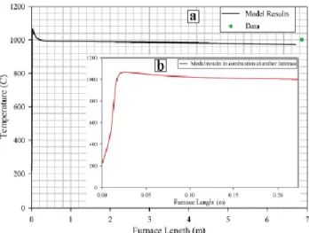
Fig. 12 shows temperature profile in combustion chamber, calculated by kinetic model. According to Fig. 12 temperature soars to as high as 1070 °C in the inlet section of combustion chamber and then because of endothermic reactions, begins to decrease gradually and finally approaches 972 °C. As an average along the bed, the temperature is around 1000 °C in the combustion chamber.
34
Fig. 13 shows H2S, CO2CO2 and H2O molar flow profiles along the combustion chamber. According to the profiles, H2S composition decreases with a sharp rate at the beginning of the gas inlet to the furnace. CO2 flow increases sharply at the inlet because of fast hydrocarbons combustion and then decreases because a part of CO2 converts to CO.
Fig. 14a shows CO, COS, SO2, S2 and H2 composition profiles along combustion chamber length. Compositions of H2, S2, COS and CO products increase sharply at initial length of the furnace then because of consumption of H2 in the reaction with syngas products its composition decreases. Similar to H2, SO2, SO2 molar flow decreases after a while and this is because of SO2 consumption in Claus reaction. After 0.5 m from the furnace inlet, CO composition remains constant until the end of thermal reactor. Because of limited resources of oxygen, a part of hydrocarbons burns incompletely and produces more CO. In addition, the burning reaction of H2 cannot progress completely because of low availability of oxygen.
Fig. 14b shows conversion of key components in combustion chamber. In this figure negative amount of conversion means production of a component and black point at the end of each profile shows conversion in real industrial data. It is obvious that all available oxygen consumes at the inlet of reactor and therefore its conversion soars to 100%, instantly. Because of high tendency of H2S to react with oxygen, H2S conversion has a high slope at the reactor inlet and then because of oxygen lack, the rate of SO2 formation decreases. The same results can be seen for CO2. At the inlet of combustion chamber, all hydrocarbons react with oxygen which produces large amounts of CO2 that its production is presented by negative conversion. As the reaction progresses, conversion trend of CO2 revolves from negative to positive amount that is because of consumption of CO2 in other reactions. H2O is the product of all combustion reactions, therefore its composition usually increases and its conversion plot is negative.
Figure 12: Temperature profile along combustion chamber length (a) total length (b)
first 0.2 m length.
Figure 13: H2S, CO2 and H2O composition profiles along
35
1.2. Lavan
The main goal of this research is to develop a mathematical model for an industrial Claus process and optimization the process performance to enhance Sulfur recovery. The conventional Claus process consists of thermal conversion in furnace and catalytic conversion in two series fixed bed rectors. The furnace and catalytic reactors are modeled based on the mass and energy conservation laws at steady state condition. To prove the accuracy of the developed mathematical model, the simulation results of the process are compared with the available plant data. Then, the optimal condition of Claus process is calculated considering Sulfur recovery as the objective function using Genetic algorithm as a useful method in global optimization. The attainable decision variables are inlet temperature of furnace and fixed bed reactors, feed distribution along the furnace and flow rate of air in the furnace.
Per the authors, the following main and side reactions take place in the thermal section:
In this study, a one-dimensional model is developed to simulate the thermal and catalytic sections of Claus process. In the considered mathematical model, the following assumptions are adopted:
Plug flow pattern is considered.
Radial diffusion of mass and energy is negligible.
The system operates at steady-state condition.
The gas mixture is an ideal gas.
The catalytic reactions take place on the catalyst surface.

![Table 2: Input and output RTR compositions for two different reactions temperatures [12]](https://thumb-eu.123doks.com/thumbv2/123dokorg/7503732.104665/29.892.202.680.100.392/table-input-output-rtr-compositions-different-reactions-temperatures.webp)
![Figure 10: Process plant scheme with pre-heating by external source [12]](https://thumb-eu.123doks.com/thumbv2/123dokorg/7503732.104665/30.892.94.799.366.775/figure-process-plant-scheme-pre-heating-external-source.webp)