RADIATION MEASUREMENTS OF A MEDICAL PARTICLE
ACCELERATOR THROUGH A PASSIVE RESONANT CAVITY
Alberto Leggieri
1,2, Franco di Paolo
1, Davide Passi
1,
Alessia Ciccotelli
2, Silvia De Stefano
2, Giuseppe Felici
2and Filippo Marangoni
21
Università degli Studi di Roma “Tor Vergata”, Dipartimento di Ingegneria Elettronica, Roma, Italy
2S.I.T. Sordina IORT Technologies S.p.A., Aprilia, Italy
Abstract
Dose measurements of a Medical Linear Accelerator (LINAC’s) performed through a passive resonant cavity are shown in this paper. The cavity is coupled through a magnetic loop with a coaxial transmission line loaded on a microwave envelope detector. Output signal has been documented while receiving electron currents ranging from several values. This paper shows the complete equivalency, in terms of global performance, of the current revelation performed by exploiting the cavity-beam interaction principle with the classical technology, based on ionization chambers, without need of high voltage. The most important point is that the resonant cavity system, by measuring the beam current, gives a direct measurement of a physical observable quantity directly related with the dose deposed by the beam.
INTRODUCTION
Real time radiation measurement represents a fundamental aspect of medical Linear Accelerator (LINAC) development. This study was leaden by the need of a beam monitoring device for which several innovations have been proposed. In the medical LINAC field, strict regulations are imposed, mostly regarding the control of the emitted radiations delivered to the target [1], [2]. In this study the investigation have involved a medical mobile electron LINAC dedicated to intra operative radiation therapy (IORT). Actual dose monitoring systems are typically based ionization chambers and require high voltage biases [3], [4].
This study investigates on the possibility of measure dose emission through the power exchange of the beam current with a passive resonant cavity [5] placed at the output interface of the accelerator. Experimental evidence is presented showing the complete equivalency of the proposed system with the traditional technology, based on ionization chambers, however without need of high voltage. The major strength of the proposed system is represented by the direct relation between the deposed dose and beam current as physical observed quantity.
OPERATION OF MEASURING SYSTEM
The proposed radiation detector is based on the power exchange of the beam current with a passive resonant cavity [5] placed at the output interface of the accelerator.
LINAC beam current have a bunched time behavior and, as the bunches follow each other periodically in time, the spectral content of the current beam is a line at the accelerating frequency f and whole-number harmonics [4]. A simplified approach can be adopted by treating the bunched current as a square wave with an amplitude Ibeam and duty cycle δ. The first harmonic would have an amplitude I1=2Ibeamsin(πδ)/π. The LINAC considered in this study, operating at f =2998 MHz, can provide Ibeam=1.11 mA, with I1=0.66 mA. This harmonic content has been employed to induce oscillations in an opportune resonant cylindrical cavity operating in the TM010 mode at
the accelerator normal mode frequency f.
Since the minimum energy of the beam is greater than 4 MeV, an opportune aluminum window (transparent to these energetic charges) is employed for allowing the beam crossing and entering the cavity. The window thickness is chosen to limit the surface scattering.
The beam current, exiting the LINAC, crosses the window and, centered on the axis, enters the cavity where image charges are induced on the walls exhibiting azimuthal symmetry [6]. While moving, they induce a wall current I0 leading the cavity in resonance. An azimuthal magnetic induction field Bϕ is generated in the cavity. A magnetic loop is placed inside the cavity volume and this field fluxes through the surface encircled by the loop, inducing a voltage Vp between the loop terminals. In order to maximize this flux, the surface enclosed by the loop is normal to the azimuthal direction.
In resonance, the cavity behaves as though its shunt impedance [6] while the loop is connected to a 50 Ω load through a coaxial line. In order to have the maximum transfer of available power, the loop shape and its distance from the axis of the cavity are chosen to have the right impedance transformation, matching the system.
For this reason it’s of vital importance that the cavity shows a critical coupling, identifiable by a coupling factor k=1. This condition can be applied by employing the “detuned short position” technique [7].
The 50 Ω load closing the loop is the input port of a RF detector diode, at whose output port the envelope of Vp is
Proceedings of IPAC2015, Richmond, VA, USA MOPHA053
6: Beam Instrumentation, Controls, Feedback, and Operational Aspects T03 - Beam Diagnostics and Instrumentation
ISBN 978-3-95450-168-7 917 Cop yright © 2015 CC-B Y-3.0 and by the respectiv e authors
reported. The detector voltage output, representative of the beam current, is forwarded to a voltage integrator where is integrated during the LINAC pulse duration, i.e. the macro-bunch. Hence, the voltage output of the integrator is representative of the charge emitted per pulse. This voltage is elaborated by a microcontroller system and the information is processed to manage the dose delivered by the accelerating machine.
This device allows for the direct measurement of a physical observable quantity directly related with the dose deposed by the beam. The proposed device does not require high voltage as happens for the ionization chambers.
DETECTOR DESIGN
One of the principal requirements for the proposed detector is the small thickness, needed to insert the system at the end of the LINAC radiant head. Moreover, the cavity needs to be integrated with another cavity to compose a redundant system composed by two cavities disposed along the same axis, as required by technical standards [1],[2]. This requirement will further reduce the available space. Hence, in order to reduce the size as much as possible, a length of λ/16, corresponding to Lgap=6.25 mm has been chosen for the initial pillbox cavity design. Another requirement regards the frequency bandwidth, since the device is subjected to thermal effects due to the variability of the external environment conditions: If the frequency of the LINAC changes without changing the frequency of the cavity detector in the same manner, the output signal will be attenuated, as regulated by the filtering effects of the cavity.
A tradeoff between the power losses and the operative bandwidth of the cavity was performed, yielding to the selection of the brass as the material for the realization of the device. A lower quality factor can make the system more robust to frequency shift but increase losses, reducing the voltage output.
In order to realize the system of two integrated cavity avoiding normal mode coupling between them, a cylindrical section has been added to the cavity to allow the beam current exiting from the first cavity to enter in another identical cavity without inserting a metallic shield. The radial aperture of such cylindrical section is enough large to allow the beam crossing without significantly increasing the electrical coupling between the two cavities. A reentrant cavity shape has been individuated by employing POISSON SUPERFISH. A complete electromagnetic modeling of the whole system composed by the cavity and the loop has been performed on ANSYS-ANSOFT HFSS. The magnetic loop has been dimensioned in order to obtain the correct impedance transformation giving the critical coupling between the cavity and the load.
FABRICATION AND MEASUREMENTS
A prototype is described with cold measurements of scattering parameters and hot measurements of the LINAC dose deposition. In order to avoid frequency shift due to temperature exposition, the cavity shares an opportune thermostatation circuit with the LINAC. The system is depicted in Fig.1, where SMA connectors, tuning screws, and liquid circuit connectors can be noted.
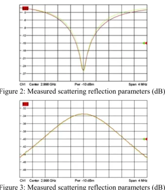
Figure 1: Prototype of the proposed radiation detector. The values of the reflection parameters have been elaborated through a custom MATLAB code, computing the quality factor and the coupling factor, as described in [7]. The input characteristic of this radiation detector have been measured in air atmosphere showing a return loss of 25 dB, an isolation between the two channels of 33.5 dB, an unloaded quality factor Q0=2.31·103 and a coupling factor k=1.1, as shown in fig. 2, 3 and 4.
In order to asses quantitatively the results achieved, a direct measurement of the accelerated beam has been performed. The beam current emitted by the LINAC has been forwarded into the envelope detector while documenting its output.
Figure 2: Measured scattering reflection parameters (dB).
Figure 3: Measured scattering reflection parameters (dB).
MOPHA053 Proceedings of IPAC2015, Richmond, VA, USA
ISBN 978-3-95450-168-7 918 Cop yright © 2015 CC-B Y-3.0 and by the respectiv e authors
6: Beam Instrumentation, Controls, Feedback, and Operational Aspects T03 - Beam Diagnostics and Instrumentation
Figure 4: Elaboration for coupling analysis.
These measurements have been performed on the LIAC-S® accelerating structure, by varying the LINAC energy settings [8]. The machine has been set with the parameters described in table 1. The pulse duration of the macro-bunch is τ=3.5 μs and the pulse repetition frequency is fPRF=10 Hz. Mean electron beam energy has been measured according to IAEA TRS 398 protocol [9]: Percentage Depth Dose (PDD) curves have been measured using PTW MP3 XS water-phantom with suitable detectors and PTW Mephisto mc2 processing software [10]. Results are shown in Fig. 5. The e-beam mean energy E0 at the water-phantom surface is given by [9], being R50 the depth where the measured dose is half with respect to the maximum.
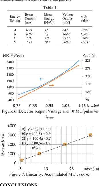
Figure 5: Percentage depth dose measurements. The detector voltage output has been forwarded to a operational integrator and integrated during the macro bunch pulse time. By elaborating the integral output through a microcontroller system, the dose monitoring has been performed obtaining a digitalized value representative of the dose emission, the monitor units per pulse (MU/pulse) [1]. The system has been calibrated to provide the precise measurement of the delivered dose to the target. Each monitor unit has been calibrated to 1 cGy. The envelope detectors have shown an output peak voltage of 300 mV, while injecting the maximum bunched beam current. The relation between the injected beam current and the output of the detector is reported in Fig. 6. Can be noted that the peak voltage output (Vout)
against the beam current shows a linear behavior and the calibrated dose digital representation in MU/pulse shows a linearizable behavior.
Measurements in Fig. 7 show the linearity of the accumulated monitor units against the accumulated dose. Measurements have been performed for each energy setting, however show the same behavior. These results allow for the employment of the proposed system in a medical electron LINAC for controlling the emission of ionizing radiation delivered to the patient.
Table 1 Energy Setting Beam Current [mA] Mean Energy [MeV] Voltage Output [mV] MU/ pulse A 0,74 5.5 84.5 0.797 B 0,89 7.1 164.0 1.570 C 1.03 9.0 253.5 2.695 D 1.11 10.5 300.0 3.534
Figure 6: Detector output: Voltage and 103MU/pulse vs
Ibeam.
Figure 7: Linearity: Accumulated MU vs dose.
CONCLUSIONS
This study shows the dose measurements of a Medical Linear Accelerator performed through a passive resonant cavity placed at the output interface of the accelerator.
This solution does not require high voltage bias as happens for traditional monitoring systems based on ionization chambers and gives a direct measurement of a physical observable quantity directly related with the dose deposed by the beam. Several measurements have been performed, showing the complete equivalency of the proposed approach with the traditional ionization-based systems but presenting several advantages.
-1 -0.5 0 0.5 1 -1 -0.8 -0.6 -0.4 -0.2 0 0.2 0.4 0.6 0.8 1 fo=2998 k=1.1128 Qo=2311 QL=1094 SWR=1 Zin=55 B=1296830
Detuned Short Position
0 20 40 60 80 100 0 20 40 60 80 Abso rbed do se (% ) Depth in water (mm) A B C D 78 128 178 228 278 328 400 900 1400 1900 2400 2900 3400 0.73 0.83 0.93 1.03 1.13 Vout (mV) 1000·MU/pulse Ibeam (mA) A) y = 99,5x + 1,5 B) y = 100,5x + 0,9 C) y = 100,4x - 0,7 D) y = 100,5x - 1,9 R² = 1 0 1000 2000 3000 4000 3 13 23 Mo nito r Units Dose (Gy)
Proceedings of IPAC2015, Richmond, VA, USA MOPHA053
6: Beam Instrumentation, Controls, Feedback, and Operational Aspects T03 - Beam Diagnostics and Instrumentation
ISBN 978-3-95450-168-7 919 Cop yright © 2015 CC-B Y-3.0 and by the respectiv e authors
REFERENCES
[1] International Standard EN 60601-2-1 “Medical electrical equipment - Part 2-1: Particular requirements for the basic safety and essential performance of electron accelerators in the range 1 MeV to 50 MeV “, 3rd edition, International
Electrotechnical Commission, 2009.
[2] A. P. Turner, “Regulations, Standards and Guidelines for the Use of Medical Electron Linear Accelerators”, IEEE Transactions on Nuclear Science, Vol. NS-26, No. 1, 1979.
[3] Uvarov, V.L. et Al., “A beam monitoring and calibration system for high-power electron LINACs”, Proceedings of the Particle Accelerator Conference, Vancouver, BC, 1997.
[4] M. Ruf, S. Muller, S. Setzer and L. P. Schmidt; “Beam Position and Energy Monitoring in Compact Linear Accelerators for Radiotherapy”, IEEE Transactions on Biomedical Engineering, Vol. 61, No. 2, 2014.
[5] J.B. Rosenzweig, “Accelerator technology II: waveguides and cavities” in Fundamentals of Beam Physics, Oxford University Press, Oxford, 2003, pp. 183-193.
[6] D.A. Goldberg and G.R. Lambertson, “Dynamic Devices a Primer on Pickups and Kickers”, pp.540-561.
[7] A. Leggieri, D. Passi, G. Felici, S. De Stefano and F. Di Paolo, “Magnetron High Power System Design”, International Journal of Simulation System Science and technology, Vol. 16, 2015.
[8] IAEA TRS 398 “Absorbed Dose Determination in External Beam Radiotherapy: An International Code of Practice for Dosimetry Based on Standards of Absorbed Dose to Water”, Vienna, December 2000. [9] PTW Freiburg GmbH, Mephysto Software Suite
product description, Germany, 2012. Available:
http://www.ptw.de/2082.html
[10] S.I.T. S.p.A., LIAC-S® product description, Italy,
2013. Available: http://soiort.com
MOPHA053 Proceedings of IPAC2015, Richmond, VA, USA
ISBN 978-3-95450-168-7 920 Cop yright © 2015 CC-B Y-3.0 and by the respectiv e authors
6: Beam Instrumentation, Controls, Feedback, and Operational Aspects T03 - Beam Diagnostics and Instrumentation