Alma Mater Studiorum · Universit`
a di Bologna
SCUOLA DI SCIENZE
Corso di Laurea Magistrale in Informatica
Design and development of a software
architecture for seamless vertical
handover in mobile communications
Relatore:
Chiar.mo Prof.
Vittorio Ghini
Presentata da:
Matteo Martelli
Sessione II
Anno Accademico 2015-2016
Copyright c 2016, Matteo Martelli, Universit`a di Bologna, Italy. This work is licensed under the Creative Commons Attribution-ShareAlike 3.0 License (CC-BY-SA). To view a copy of this license, visithttp://creativecommons.org/licenses/ bysa/3.0/or send a letter to Creative Commons, 543 Howard Street, 5th Floor, San Francisco, California, 94105, USA. The network topology icons used in figures of this document are property of Cisco Systems, Inc. Use of these element icons (in an unmodified format) is authorized, without additional permission from Cisco.https://www.cisco.com/cisco/web/ siteassets/contacts/index.html,https://www.cisco.com/c/en/us/about/brand-center/network-topology-icons.html.
Sommario
Gli ultimi anni sono stati caratterizzati da una notevole crescita di ven-dite di smartphone. Si prevede infatti che per il 2017 pi`u di un terzo della popolazione mondiale ne posseder`a almeno uno. Questi dipositivi, insieme alle odierne tecnologie wireless, ci forniscono quotidianamente accesso ad In-ternet e la possibilit`a di interagire con il resto del mondo da qualsiasi luogo in cui ci troviamo e durante ogni nostro spostamento. Ad ogni modo so-no tuttora molte le problematiche da affrontare affinch`e le attuali tecso-nologie riescano a garantire alta qualit`a ed affidabilit`a nei servizi utilizzati, soprat-tutto se di tipo real-time come ad esempio comunicazioni VoIP, servizi di videoconferenza o servizi di online gaming.
Ulteriori complicazioni sorgono quando suddetti servizi vengono utilizzati da utenti di dispositivi mobili durante i loro spostamenti geografici. Si pensi per esempio ad un utente dinamico che partecipa ad una videoconferenza di lavoro mentre si sposta da casa ad un altro luogo, e a come questo uten-te possa utilizzare uno smartphone per continuare ad inuten-teragire con i suoi colleghi fuori casa usufruendo della rete dati cellulare. Se con le classiche comunicazioni telefoniche cellulari siamo abituati alla continuit`a di servizio, possibili interruzioni di una comunicazione online (over IP) potrebbero inve-ce verificarsi se un utente si sposta da un tipo di rete ad un altro, ad esempio da WiFi a rete dati cellulare.
In questo lavoro nello specifico presento in prima istanza una panorami-ca sulle attuali tecnologie wireless e sulla mobilit`a, concentrando l’attenzio-ne sulle difficolt`a e le problematiche che sorgono quando dei nodi mobili si spostano tra punti di accesso di tecnologie diverse mentre utilizzano com-municazioni e servizi real-time. In letteratura sono molte le soluzioni che propongono diversi metodi e architetture software con lo scopo di migliorare l’handover verticale, ovvero l’azione di trasferire una comunicazione tra due reti eterogenee.
Secondariamente, dopo aver analizzato le possibili soluzioni esistenti, il documento presenta un meccanismo di handover verticale per smartphone Android implementato dal sottoscritto. Viene introdotto inoltre un confronto sulle prestazioni e sull’affidabilit`a tra tale sistema implementato e l’attuale sistema Android, entrambi testati in uno scenario in cui l’handover verticale avveniva tra reti WiFi e reti cellulari mentre i nodi si servivano di servizi di video streaming. I risulati di tale confronto mostrano come l’approccio utilizzato nella mia implementazione sia promettente incoraggiando tuttavia futuri sviluppi, alcuni di questi proposti alla fine del documento insieme alle considerazioni finali.
Abstract
In this work I firstly present an overview on current wireless technology and network mobility focusing on challenges and issues which arise when mobile nodes migrate among different access networks, while employing real-time communications and services. In literature many solutions propose different methods and architectures to enhance vertical handover, the process of trans-ferring a network communication between two technologically different points of attachment. After an extensive review of such solutions this document de-scribes my personal implementation of a fast vertical handover mechanism for Android smartphones. I also performed a reliability and performance com-parison between the current Android system and my enhanced architecture which have both been tested in a scenario where vertical handover was taking place between WiFi and cellular network while the mobile node was using video streaming services. Results show the approach of my implementation to be promising, encouraging future works, some of which are suggested at the end of this dissertation together with concluding remarks.
Introduction
According to current statistics[33][27], the number of smartphone ship-ments have almost tripled in the last five years and figures are still increasing. It is expected that by 2017, more than one in three people globally will have a smartphone. Such devices are nowadays almost always connected to the Internet giving users the opportunity to constantly interact with the rest of the world. Also wireless technologies and broadband systems are strongly improving over time providing more reliability and higher data rates. This drives users to involve more intruiguing and more performance demanding services such as high definition voice and video calls, live video broadcasts and online gamining. While employing these kind of services and their re-lated real-time applications, users may move geographically among different point of attachments to the Internet. Ensuring that no service interruption is perceived by users in this scenario is a complex task.
The process of moving between different wireless network is referred to handover (or handoff ) and in literature many works focus on finding the best way to manage situations in which handover takes place while users employ real-time communications. After having inspected these related works I de-cided to develop a set of software components and tools which aim to help the vertical handover process on mobile devices.
In the first three chapters of this document we will see what mobile com-munications consist of and which problematics mobility architectures have to deal with. Chapters4and 5will then focus on the design choices and the development process of my personal project. In chapter 6 I will show how
iv INTRODUCTION
my project suits well in a practical scenario through experimental results. Finally, in the last chapter some possibile future works will be addressed togheter with concluding considerations.
Before facing three lengthy chapters about the state of the art on current wireless techonology and mobility related works, the following section sums up the main characteristics and goals of my personal project in order to introduce readers to the software I implemented.
Summary on my personal project
I worked on improving the handover process which takes place when An-droid smartphones move from a WiFi technology access network to a cellular technology access network and back while using a real-time video streaming service. Currently such smartphones use a network technology with consid-erable periods of service disruption during the network switch. The basic idea behind my project is to allow smartphones to simultaneously use both network technologies with the aim of improving handover reliability and per-formances without involving any user application modification. This idea comes from the ABPS project[53] which will be introduced in next chapters. My implementation efforts took care of enhancing an existing software mod-ule, called TED, designed to work with the linux kernel. Also I developed a set of proxy applications which interact with each others, with TED and with user applications. At the end I evaluated the overall enhanced system behaviour by conducting a series of experiments.
Contents
Introduction iii
1 Overview of mobile communications 1
1.1 Current scenarios . . . 1
1.2 Mobililty . . . 3
1.2.1 Current technologies . . . 3
1.2.2 Goals and issues . . . 8
2 Seamless vertical handover: state of the art 9 2.1 Handover criteria . . . 11
2.2 MN-controlled Vertical Handover . . . 12
2.2.1 Media Independent Handover . . . 12
2.2.2 Transmission Error Detector . . . 13
2.2.3 Enabling/Disabling NICs . . . 13
3 Seamless host mobility: state of the art 15 3.1 Solutions at the network layer . . . 15
3.1.1 Mobile IP . . . 15
3.1.2 LISP . . . 18
3.2 Solutions between the network and the transport layer . . . . 19
3.2.1 LIN6 . . . 19
3.2.2 Shim6 . . . 19
3.3 Solutions at the transport layer . . . 20
3.4 Solutions at the session layer . . . 21
vi CONTENTS
3.4.1 SIP . . . 21
3.4.2 Jingle . . . 22
3.4.3 Non standard signaling . . . 24
3.5 NAT and Firewall issues . . . 24
3.6 External relay solutions . . . 25
3.6.1 ABPS . . . 25
3.6.2 UPMT . . . 28
3.6.3 FRHP . . . 28
4 Project goals and design 31 4.1 Project goals . . . 31
4.2 Mobile node . . . 32
4.3 Relay and Correspondent Node . . . 37
5 Project development 39 5.1 TED . . . 39
5.1.1 Previous versions and working principles . . . 39
5.1.2 IPv6 Fragmentation Support . . . 42
5.1.3 TED porting on android custom linux kernel 3.4 . . . . 45
5.1.4 Refactoring . . . 46
5.1.5 Open issues . . . 47
5.2 Proxy Client . . . 48
5.2.1 Network . . . 48
5.2.2 Handover parameters . . . 50
5.2.3 Basis for datagram retransmission . . . 51
5.3 Relay and CN tools . . . 51
6 Experimental tests 55 6.1 Experimental Setup . . . 56
6.2 Experimental Results . . . 58
CONTENTS vii
A Testers and developers documentation 69
A.1 TED kernel and proxy application . . . 69
A.1.1 Build Linux kernel . . . 70
A.1.2 Android . . . 71
A.1.3 Patch the kernel . . . 73
A.2 Build and run tedproxy . . . 78
A.2.1 Build . . . 78
A.2.2 Run . . . 79
A.3 Relay and CN tools . . . 80
A.3.1 Relay . . . 80
A.3.2 CN tools . . . 80
A.3.3 Put everything together . . . 81
List of Figures
1.1 Mobility scenario . . . 2
2.1 Horizontal Handover . . . 10
2.2 Vertical Handover . . . 10
3.1 MIPv4 Triangular Routing . . . 17
3.2 LISP data-packets encapsulation and decapsulation . . . 18
3.3 Jingle signaling and media relaying . . . 23
3.4 Employment of a data relay to cope NATs and firewalls . . . . 25
3.5 The ABPS architecture . . . 27
4.1 MN desigin structure . . . 32
4.2 Android Platform Architecture . . . 34
4.3 Picture of the MN device . . . 36
5.1 IPv6 Fixed Header format . . . 43
5.2 IPv6 Framgent Extension Header format . . . 43
5.3 tedproxy internal output queues and socket input queues . . 49
6.1 Experimental setup. . . 56
6.2 Camera streamer application error . . . 59
6.3 Results with TED and tedproxy disabled . . . 60
6.4 Results with TED and tedproxy enabled . . . 60
6.5 Results with TED and tedproxy disabled and application er-ror occurrence . . . 62
Chapter 1
Overview of mobile
communications
In the last years users gained easy access to both mobile terminals and high bandwidth connections. In fact, both smartphones and wireless tech-nologies rapidly evolved offering daily use of the Internet to their users. Voice over IP (VoIP) and more generally real-time communications are increasingly used in daily communications.
Typical scenarios, current technologies and common goals and challenges in the context of network mobility will be introduced in this chapter.
1.1 Current scenarios
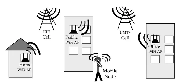
Modern cities are frequently covered with several public WiFi Access Points (APs) which allow citizens and tourists to freely connect to the Inter-net. Also, users may have personal access to private WiFi APs all over the city or other daily visited locations. Moreover, users of smartphone devices may likely have access to the Internet throgh cellular networks which provide packet switching subsystems. For instance, let us consider a mobile terminal user whome daily walks from its home to its workplace while making VoIP calls. Let us assume that it mainly uses cellular networks for data exchange
2 1. Overview of mobile communications Public WiFi AP Home WiFi AP UMTS Cell Mobile Node Office WiFi AP LTE Cell
Figure 1.1: Mobility scenario
and that it encounters several WiFi APs along the path, for example its home WiFi AP, some public WiFi APs and its office WiFi AP (figure 1.1). Since data connection plans of cellular networks are usually provided with metered data traffic, the user may prefer WiFi APs when available as they often provide access to unmetered data traffic connections. Moreover, the user may prefer WiFi over cellular network since the network coverage of the latter may be poor in some indoor rooms, thus causing considerable battery drain. On the other hand, communications over the cellular network may be preferable when WiFi connectivity starts to deteriorate, for example moving away from the AP or when the user is served by public APs in crowded places (congestion).
Switching from one type of connection technology to another may cause noticeable interruptions in the ongoing real-time conversations due to the considerable amount of time needed for the handover to take place. Handover is the process of moving between different wireless networks and it will be described in the next chapter.
1.2 Mobililty 3
1.2 Mobililty
The term mobility refers to the ability to move freely and easily. In com-puter networks, support for mobility refers to the ability to keep communica-tions active during movement across different networks. More challenges arise when communications are real-time, thus including VoIP, video-conferences, online gaming, screen sharing and so on. Mobility support for real-time communications is a hot research topic since it is considered a complex task that involves many heterogeneous technologies and agents whose character-istics are constantly evolving. In fact, a wide range of solutions that aim to support mobility have been proposed in literature. They focus on different aspects and operate at different layers of the protocol stack. However, they often share the same goals, deal with similar issues and refer to a common terminology. In particular, end-node terminals which can move across net-works are often called Mobile Nodes (MNs), and end-node terminals which are fixed and do not experience frequent network re-configurations are called Correspondent Nodes (CNs). Generally both entities are taken into account in order to cover two different typical situations: in the first scenario both end nodes involved in the communication are MNs while in the second more relaxed scenario one end-node is an MN and the other one is a CN. We will see in the chapter3how some of the existing solutions suit well for the second scenario but do not satisfy the necessary requirements when both end-points can move to a different network at the same time.
1.2.1 Current technologies
Mobile devices are able to access the Internet network through wireless points of attachment. Wireless technologies can work with short or long range radio systems. Currently, the most used short range wireless technologies are the following.
WiFi: WiFi (Wireless Fidelity) specifications are defined by the IEEE 802.11
4 1. Overview of mobile communications
(WLAN) network. WiFi mainly operates at 2.4GHz and 5GHz fre-quencies. Coverage range depends on many factors such as the specific 802.11 protocol the AP runs (a/ac/b/g/n/etc.), the transmitter power, which antennas are used, the position of the AP (indoor or outdoor) and so on. Anyway, the coverage range of typical WiFi installations can vary from around 20 meters to 150 meters[70]. Like the coverage range, also the experienced data rates can vary depending on many factors. For instance, when the perceived signal is weak, WiFi stations tend to operate at more reliable modulation schemes which ensure stable com-munications but decrease the data rate. The majority of WiFi devices are currently 802.11g and 802.11n compatible, offering maximum data rates of 600Mbps with the 5GHz band. Anyway, it is worth noting that at the time of writing, only few broadband internet access plans can offer such data rates.
Bluetooth: Bluetooth is a wireless technology for exchanging data using
short range radio transmissions. Specifications and services are man-tained by the Bluetooth Special Interest Group (SIG). Bluetooth was intended for building Wireless Personal Area Networks (WPANs) used for interconnecting personal devices in a short-range area. It is de-signed for low power consumption indoor work. Coverage range can vary from around 50cm to around 100 meters. Like the WiFi technol-ogy, Bluetooth operates in the ISM radio band at 2.4GHz. Bluetooth Low Energy[5] and Bluetooth High Speed[4] are two extensions which expand on the Bluetooth application use case. The first one is intended to work with devices that run for very long period of time thanks to its power efficiency, while the second lets users quickly exchange large amount of data by momentary enabling a second radio.
Generally, WiFi prevails over Bluetooth when devices must access the Internet as it enables faster connections (higher bit-rates), better range from the base station and better security. In any case, when MNs are not covered by any WiFi AP, they rely on cellular network technologies which operate
1.2 Mobililty 5
with long range radio system. Cellular networks technology can be classified by their generation number[71][47].
1G: In the first generation of cellular networks, the concept of cell system
were introduced (Japan 1979, US 1984). A cellular network is composed by many cell sites, each covering a small area. The basic idea was to assign a different operating frequency to each cell, allowing partial overlapping.
2G: In the second generation of cellular networks (late 1980s), analog cell
systems were replaced by digital, circuit-switched cell systems defined by the GSM standard. Voice calls started to be digitally encoded and compressed allowing more calls to be transmitted in the same amount of radio bandwidth. Other benefits introduced by digital signal were encrypted conversations and data services such as SMS text messages and emails.
2.5G: General Packet Radio Service (GPRS) is a 2G-3G transitional
tech-nology, thus often called 2.5G. GPRS was developed, and opened in 2000, to build packet-switching systems on the existing GSM networks which were circuit-switching based. The main advantages introduced by GPRS are the support for IP networking and higher data-rates, typical 56Kbps downlink and 14.4Kbps uplink, compared to GSM data rate, max 9.6Kbps both downlink and uplink. The popularity of GPRS soared thanks to its ease of deployment. In fact, to provide GPRS ser-vices on the top of GSM, it was sufficient to add few GPRS Support Nodes (GNS), which acted as gateways to the Internet network, and to do some other small changes to the existing 2G networks.
2.75G: Enhanced Data Rates for GSM Evolution (EDGE) was invented and
introduced by AT& T (former Cingular) as an upgrade to the existing GPRS and 2G networks. EDGE substantial enhancements are at the physical layer which includes a new form of modulation: 8 Phase Shift Keying (8PSK) also used in 3G networks. The new modulation method
6 1. Overview of mobile communications
allowed data communications to be exchanged at a typical data rate of 384Kbps and the already existing GPRS infrastructure could be used.
3G: 3G is a family of standards used for mobile devices and mobile
telecom-munication services that comply with the International Mobile
Telecommunications-2000 (IMT-2000 ) specifications by the Interna-tional Telecommunication Union. Telecommunications companies em-ploying networks advertised as 3G had to fulfill the IMT-2000 re-quirements. Many technologies were accepted as 3G standard like CDMA2000 developed in US, WCDMA (Wideband-CDMA) developed in Europe and SCDMA developed in China. WCDMA and TD-SCDMA are both access methods used in the Universal Mobile Telecom-munication System (UMTS) technology officially launched in 2002. WCDMA uses a code division multiple access method (as the UMTS competitor CMDA2000) while TD-SCDMA combines both code divi-sion and time dividivi-sion multiple access methods.
Data rates in 3G networks can reach around 2Mbps downlink and 384Kbps uplink with UMTS. Later enhancements of UMTS are High Speed Downlink Packet Access (HSDPA) and High Speed Uplink Packet Access (HSUPA) which belong to the High Speed Packet Access (HSPA) family, sometimes also called 3.5G. A later version of HSPA called HSPA+ enables data rates up to 42Mbps introducing MIMO (Multiple-Input, Multiple Output) technology and higher order modulation (64QAM) techniques.
4G: The fourth generation of cellular networks is intended to be an all-IP
based solution. The purpose is to integrate different radio access net-works together relying on the Internet network as the backbone. The IMT-Advanced is a set of requirements for 4G standards and defines 100Mbps and 1Gbps as the peak speeds for high mobility communica-tions (e.g. trains, cars) and low mobility communicacommunica-tions (e.g. pedes-trians) respectively. Even if LTE and WiMax technologies do not fulfill
1.2 Mobililty 7
the IMT-Advanced requirements, the ITU Radiocommunication Sector (ITU-R) agreed that the term “4G” can be applied to these technolo-gies since they provide a substantial improvement with respect of the 3G technologies. ITU indicated “LTE-Advanced” and “WirelessMAN-Advanced” as the official designation of IMT-Advanced[22]. In fact, 4G with LTE-Advanded can reach data peak speeds of 1Gbps down-link and 500Mbps updown-link, which is considerably higher than the respec-tive 100Mbps downlink and 50Mpbs uplink of LTE and WiMax. 4G requirements also mandate smooth handoff across heterogeneous net-works, global roaming across multiple networks and spectral efficient system. Orthogonal Frequency-Division Multiple Access (OFDMA) was chosen as the multiple access method to the wireless medium.
5G: At the time of writing, there is no standard for 5G deployment. The
Next Generation Mobile Networks Alliance defines some requirements the fifth generation of cellular networks should fulfill[75]. They focus on increasing the capacity support of the mobile networks, allowing high data rate communications for more users per unit, reducing la-tency, enhancing the spectral efficiency and supporting the Internet Of Things and massive wireless sensor networks requirements. The Next Generation Mobile Networks Alliance’s work tries to cover the expected scenarios and challenges of 2020, covering measures that may support the expected dramatic increase of the data volume by that date. Since in some areas, cells and cellular network subsystems do not still pro-vide support for new technologies, smartphone users can experience different data rates and throughputs in their communications. A recent report[32], shows the comparison between 3G and 4G worldwide coverage. While many countries are improving their 4G coverage, many areas around the world lack of 4G coverage. A quote from the report well summarizes the current situation of 3G and 4G network coverage in Europe:
8 1. Overview of mobile communications
infrastructure. In Germany, Italy, France and the U.K., the chances a 4G subscriber will connect to an LTE network are little better than a coin flip.
Furthermore, many carriers around the world decided to turn off their GSM networks in 2017 in order to free up more bandwidth for faster 3G and 4G networks. However since many older devices and legacy services are still using 2G networks, some network operators in Europe will postpone the GSM turnoff date[24].
1.2.2 Goals and issues
Research in network mobility focuses on the main task of guaranteeing continuative network connectivity to mobile devices as they move geographi-cally. This is not an easy task since we live in a world of heterogeneous wire-less networks which all merge into the global Internet infrastructure, built and designed in the era of wired networks. Things become more difficult if voice and video real-time applications are involved, since they often require high data rates and low latencies. It is true that wireless technologies and broadband systems are strongly improving but at the same time users are ex-pecting more reliability, better service quality from mobile communications and support for new use cases such as high definition video broadcasts and calls, augmented/virtual reality online games[30], real-time data streaming from sensor networks and so on.
In the next chapters we will see many solutions that cover network mobil-ity. After that, an implementation of an early-packet-loss-detection method will be described in this document as my personal contribution to the Always Best Packet Switching (ABSP) project, which aims to improve the handover process and the continuative network connectivity in VoIP communications.
Chapter 2
Seamless vertical handover:
state of the art
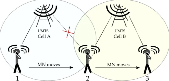
A mobile node can connect to the Internet through connection points of the wireless access networks (e.g. WiFi, LTE, etc.), often called points of attachment. Handover (or handoff) is the process of transferring a network communication from one point of attachment to another. A handover process is called seamless if the MN does not perceive any interruption while moving between two points of attachment. There are two different types of handover: horinzontal, when the MN moves between access points of the same wireless technology (e.g. between two UTMS cells), and vertical, when the MN moves between access points of different wireless technology (e.g. switching between WiFi to cellular network and viceversa). The figure 2.2 outlines the two different types of the handover process.
MNs can be equipped with multiple Network Interface Cards (NICs) since they can connect to different wireless technologies access points. In fact, today’s common MNs are often equipped with a WiFi NIC and a cellular network NIC. Thus, this document focuses on the vertical handover process which takes place when MNs move between WiFi networks and cellular net-works and back. In this chapter we will cover various approaches and metrics that may be considered for the handover decision.
10 2. Seamless vertical handover: state of the art UMTS Cell B UMTS Cell A
1
2
3
MN moves MN movesFigure 2.1: Horizontal handover: a MN changes access network using the same NIC, while moving.
UMTS Cell
1
2
3
MN moves MN moves Public WiFi APFigure 2.2: Vertical handover: a MN changes access network and the NIC used, while moving.
2.1 Handover criteria 11
2.1 Handover criteria
The decision of whether to perform a handover is taken according to status information constantly gathered by the MNs about current and the neighbor access networks. In literature, some works[51][88][63] outline the metrics that can be used for the handover decisions. The most frequently used metrics or most considered in research are:
RSSI: The Received Signal Strength Indicator (RSSI) is a measurement of
the power level being received by a radio interface. Thus the higher the RSSI, the stronger the signal. Currently, Signal Strength is one of the most used metrics for handover decision as it directly relates to network coverage. It is calculated at the physical layer of the NIC and continuously updated by the MN while moving in order to determine if network coverage is still available.
Bandwidth: Bandwidth is directly related with QoS. Sometimes the signal
strength metric is not sufficient to determine which network can offer a better service quality, for instance when two networks of different access radio technologies overlap. In this case it may be convenient to choose the access network which can provide the higher bandwidth. The maximum bandwidth can be easily estimated from the type of radio technology if the modulation scheme is known. However, the actual bandwidth may be far lower than the estimated one. Thus, the actual bandwidth calculation may require some practical tests which are often time consuming and can slow down the handover process. It is worth mentioning that bandwidth per user may also vary depending on the network load.
Frame Retransmission: Another metric that can be used for the handover
decision is the number of frame retransmissions. Like the RSSI, the number of frame retransmissions can be used to estimate the reduction of signal strength: the higher the retransmission number, the weaker
12 2. Seamless vertical handover: state of the art
the signal. Moreover, a high number of frame retransmissions may indicate the presence of radio interference. In this case the RSSI may not be affected and thus may fail to indicate low link quality[62].
Battery Power: One of the handover metrics that can be considered is the
battery power. Sometimes it may be preferable to handover to the more power efficient network.
Traffic limit: At the time of writing, Internet access through cellular
net-works is often limited in the amount of traffic, for instance a user can navigate at full speed only up to N GigaBytes of traffic per month. Hence this may be considered in the handover decision but obviously it is directly dependent on the user’s mobile plans and user preferences.
2.2 MN-controlled Vertical Handover
The handover process between cellular network cells or between WiFi APs is controlled or partially assisted by the network subsystems. Differently, the handover process between a WiFi network and a cellular network must be entirely controlled by the MN since there is no external link-layer entity that can interconnect the two networks.
In this section we will analyze some mechanisms and software tools devel-oped for handling the vertical handover process between WiFi and cellular networks.
2.2.1 Media Independent Handover
The IEEE standard 802.21[84] defines a media-independent handover (MIH) framework that includes a set of tools to exchange information, events and commands between heterogeneous link-layer entities in order to facilitate the vertical handover process. It requires the implementation of an additional layer of the protocol stack, between the data-link-layer and the network layer,
2.2 MN-controlled Vertical Handover 13
on both mobile terminals and network entities (such as APs) in order to pro-vide a standard interface of interaction. ODTONE is an implementation of the 802.21 standard, developed as an open source OS independent MIH framework. The ODTONE interface that communicates with the link-layer devices is called Link SAP whose current implementation offers only two types of events that can be used as handover metrics: link down and link up events[14]. Anyway, the Link SAP interface can be enanched with future extensions[17].
2.2.2 Transmission Error Detector
Transmission Error Detector (TED) is a component of the Always Best Packet Switching (ABPS) [53] architecture and it is essentially a software tool able to provide the MN with 802.11 data-link-layer information about frame retransmissions and successful (unsuccessful) frame receptions at the AP. TED can then deliver this information to the software modules at the application layer providing metrics for the handover decision. Currently, TED supports WiFi only but it could be extended to other technologies in the future.
The ABPS architecture, that will be described in the next chapter, and the TED module are the bases for my personal project which will be explained in details in the chapter 4.
2.2.3 Enabling/Disabling NICs
In order to save battery power, smartphone users often tend to disable the NIC that is known to be useless in certain situations or for a certain period of time: for instance, users may turn off their WiFi NIC while walking away from their home WiFi AP and they are sure there will be no accessible WiFi APs along the path they’re going to traverse.
The automatic vertical handover operation requires all NICs to be active in order to perform scans looking for suitable points of attachment. In [50],
14 2. Seamless vertical handover: state of the art
the authors of ABPS proposed a solution called “Oracle” that automatically understands when to activate or deactivate NICs according to geo-located information about WiFi APs. Essentially, the geographic positions of user accessible WiFi APs are stored in a local database on the MN during an initial mapping phase. Later in the daily use of the mobile device the database is frequently queried in order to deactivate the WiFi NIC when not needed, for example when, according to the database, there is no suitable WiFi AP within a suitable distance. Moreover, the Oracle can decide to deactivate the cellular network NIC when the MN is associated to a WiFi AP and to re-activate it when the WiFi communication starts to deteriorate (using RSSI or other QoS metrics). A recent implementation of the Oracle for Android devices has been developed by Luca Milioli in his master’s thesis work[55]. He has also introduced a functionality to geo-localize the WiFi APs according to the identifiers of cellular network cells. Even if less accurate than GPS geo-localization, this method is less battery consuming.
It is clear that the Oracle does not perform vertical handover by itself, but it is an interesting tool able to optimize power consumption in multi-homed mobile devices that employ vertical handover features.
Chapter 3
Seamless host mobility: state of
the art
In the previous chapter, we have seen some of the fundamental aspects of several vertical handover mechanisms. Those mechanism mostly give the end user devices the capability to decide whenever it might be reasonable to move from one layer 2 access technology to another. However, other elements must be taken into account while dealing with host mobility, such as communica-tion continuity and reachability. In fact, after a Mobile Node (MN) performs a handover, it should remain reachable from its Correspondent Node (CN) and the previously initiated communication should not be interrupted.
A recent survey[51] exhaustively analyses the main architectural solutions for mobility support in wireless networks. In the following sections some of them will be covered, leaving out those which are conceptually similar and share the same approach with the most noted ones.
3.1 Solutions at the network layer
3.1.1 Mobile IP
Mobile IPv4 (or MIPv4 )[77] and Mobile IPv6 (or MIPv6 )[78] are two IETF standard network protocols that were introduced in order to address
16 3. Seamless host mobility: state of the art
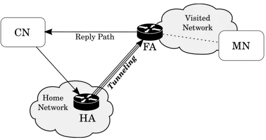
the need of MNs to be reached while moving between different IP sub-networks. In fact, the IP protocol assumes that a node’s point of attach-ment to the Internet is uniquely identified by its IP address. Thus, when a node accesses the Internet through a different sub-network, it changes its IP address as well, and packets destined to its old IP address would be dropped. The key idea behind Mobile IP is that each MN is always identified by two IP addresses, a home address and a care-of address. When a MN is at home, it can be directly reached through its home address. Otherwise when it is situated away from its home, IP packets addressed to its home address are routed to its care-of address, which correspond to the node’s current location.
The IPv4 version of the Mobile IP protocol introduces new entities called agents:
Home Agent: a router that tunnels and forwards IP packets to the MN
when it is away from home. It is located on a MN’s home network and maintains an up-to-date node’s care-of address.
Foreign Agent: a router which is located on the MN’s current network,
when this is different from its home network. The Foreign Agent is responsible of de-tunneling and delivering to the MN packets tunneled by the Home Agent.
Figure3.1 shows the communication paths between the CN and the MN. As introduced before, we notice that all the packets transmitted by the CN are directed to the Home Agent which tunnels and forwards all traffic to the current Foreign Agent. It is worth noting how the traffic originated by the MN is directly routed to the CN without involving the Home Agent. This routing scheme is often called triangular routing, since the backward routing path is different from the original routing path.
In [60] and [57], the authors cover some of the issues that MIPv4 leads to. One of the most discussed is the ingress filtering: a protection filter mechanism against IP address spoofing attacks widely used in routers[39][49].
3.1 Solutions at the network layer 17 Home Network
CN
HA
FA
MN
Visited Network Reply Path Tunne lin gFigure 3.1: Mobile IPv4 Triangular Routing.
To overcome this problem, reverse tunnelling[72] was introduced in MIPv4. Its main downside resides is its inefficiency. In fact, as the authors of [69] state, “reverse tunneling causes lower mobile connection throughput and higher roundtrip times”.
MIPv6 has several benefits over MIPv4. This is mostly given by the inner features of IPv6, such as neighbour discovery and address auto-reconfiguration[46]. Furthermore, the Foreign Agent is no longer required by the fact that an IPv6 MN obtains a new unique IPv6 address when it moves to any different ac-cess network. Obviously, MIPv6 only works on infrastructures with IPv6 capabilities.
Monami6[85], a later extension of MIPv6, allows MNs to register multi-ple care-of addresses to their Home Agents. With this approach, a MN can configure an IPv6 global address for each of its NIC. In fact, Monami6 in-troduces the multihoming capability in MIPv6. Besides that, all the Mobile IP approaches do not overcome the potential presence of symmetric firewall systems.
In the next sections we will cover more solutions and protocols concerning host mobility.
18 3. Seamless host mobility: state of the art
Figure 3.2: LISP data-packets encapsulation and decapsulation[42].
3.1.2 LISP
Location/ID Separation Protocol (LISP)[48] is another network layer tun-neling solution. LISP considers two type of IP addresses: Endpoint Identifiers (EIDs), which identify hosts, and Routing Locators (RLOCs), which identify network attachment points.
Essentially, when a host A wants to communicate with a second host B, it transmits its data to the EID IP address of the second host. When data-packets originated from A reach the first LISP-enabled border router, the Mapping System finds the RLOC identifier which corresponds to the EID of B. Packets are then encapsulated and sent to the exit LISP-enabled border router, identified by the found RLOC, which the host B is attached to. This latter router eventually decapsulates and forwards the packets originated by host A to host B. Figure 3.2 shows these LISP tunnelling operations.
When a host changes its point of attachment, its EID will remain un-changed but it will obtain a new RLOC identifier. Also, the Mapping System will take care of updating the EID-to-RLOC binding. Leaving aside the de-tails of the Mapping System entities and operations, it is worth noting that LISP introduces some form of NAT traversal[64]. However it is clear that
3.2 Solutions between the network and the transport layer 19
the main drawback of this architecture is the requirement of LISP-enabled border routers.
3.2 Solutions between the network and the
transport layer
Location Independent Addressing for IPv6 (LIN6 )[66] and Shim6 [74] are two of the existing solutions that insert an intermediate layer between the network and transport layers of the protocol stack.
The main downside of this type of architectures is the requirement to modify the protocol stacks of both the MNs and the CNs. While it may be reasonable for the MNs to support specific mobility implementations of the protocol stack, the CNs may not be interested in such mobility support.
3.2.1 LIN6
The LIN6 architecture is the IPv6 compatible implementation of LINA, which stands for Location Indipendent Network Architecture. Similarly to LISP, LINA’s basic idea is to introduce two concepts that are node identifier and interface locator. Instead of splitting the IP addresses and tunnelling data, the authors of LINA and LIN6 propose to split the network layer of the current protocol stacks in two sublayers: an identification sublayer and a delivery sublayer. Moreover, LINA uses Mapping Agents at the identification sublayer to deal with the resolution of the interface locator which correspond to an actual node indentifier. Mapping Agents can be located externally to the nodes’ networks and their addresses must be obtained through DNS lookups before being cached.
3.2.2 Shim6
Shim6’s approach is based upon adding an additional layer between the network and the transport layers. Shim6 proposes the use of network layer
20 3. Seamless host mobility: state of the art
IPv6 addresses as locators and Upper Layer Identifiers (ULID) for nodes identification.
Shim6 defines a mechanism of failure detection used to detect outages. In case of outage, Shim6 uses the Reachability Protocol (REAP)[34] to de-termine and update valid locator pairs. Moreover, unlike the previously described solutions, the approach of Shim6 for locator updates is related to timer expiration and not to movement detection. For this reason it has been considered not suitable for highly dynamic environments[51].
3.3 Solutions at the transport layer
Many solutions that work at the transport layer consider the end nodes as proactive location registry. In fact, in many protocols such as Datagram Congestion Control Protocol (DCCP)[65], Mobile Stream Control Transport Protocol (m-SCTP) [86] and TCP enhancement TCP-migrate[82], each end-system directly informs the CN when its IP address changes. This approach fails when both the end nodes involved in a communication are mobile and try to simultaneously perform a handover. It is obvious that both the MNs may become mutually unreachable since there is no third agent involved in the communication.
To overcome the mutual unreachability issue, MSOCKS[68] proposes the use of an external proxy that splits the TCP connection between two end-points. With this scheme, the external proxy can migrate a connection when the MN changes its IP address. In addition, the proxy relies on a tech-nique called TCP Splice that, as stated by the MSOCKS authors, “gives split connection proxy systems the same end-to-end semantics as normal TCP”. Essentially the goal of a TCP Splice is to let the end nodes believe they are directly connected by a single TCP connection. To achieve this goal, the TCP Splice technique is implemented by altering the headers of TCP packets, including TCP ACKs, received from one connection to make them appear to belong to the second connection. It is worth noting that this
ap-3.4 Solutions at the session layer 21
proach is not compatible with IPSec since the content, or even the headers, of IP packets, may be encrypted and alterations of IP and TCP headers may not be feasible. The authors of [43] point at the existence of this downside for a similar approach used by Performance Enhancing Proxies (PEPs)[41].
3.4 Solutions at the session layer
A key-role in establishing sessions between end nodes might be played by signalling protocols. These protocols deal with the initialization and con-trol of communication sessions and multimedia streams. Since a signalling method is fundamental for establishing multimedia communications between end nodes, we review in this section the basic properties and functionalities of two common and widely used signalling protocols: the Session Initiation Protocol (SIP)[79] and Jingle[67], a signaling method extension for the Ex-tensible Messaging and Presence Protocol (XMPP)[80]. Let us notice that after a communication session is initiated, the multimedia streams exchanged between the end nodes often rely on the Real-Time Transport Protocol (RTP) and the RTP Control Protocol (RTCP). They run over UDP and are used to transfer and control real-time traffic. Sometimes multimedia streams can be directly exchanged with UDP or TCP.
3.4.1 SIP
SIP works at the session layer of the protocol stack and relies on SIP public servers for end nodes discovery. Each end-point user has a unique SIP identifier. SIP users, before communication initiation, must register to a SIP registrar server. The SIP registrar server sends back their contact list to end-users where each contact corresponds to a hostname (or IP address). When a user A wants to initiate a SIP-communication with B, it sends an INVITE message directly to B. If some communication parameter changes (such as IP address), a re-INVITE message can be used.
22 3. Seamless host mobility: state of the art
that play the role of routing requests between end nodes. This gives the opportunity to user A to send an INVITE message to user B through a proxy server which will take care of finding the next SIP hop (the client B or another proxy). With this approach end nodes do not need to deal with configuration changes of their counterparts.
However the SIP architecture introduces an additional delay due to the message/response behaviour. In particular when an MN changes its IP ad-dress, it interrupts the communication, sends a re-INVITE message to the CN and resumes the transmission only after receiving a response from the CN. Clearly this behaviour does neither satisfy mobility efficiency goals nor seamless handover requirements. To optimize handover management of SIP-based mobile communications, the authors of [36] propose a technique for session continuity that exploits a SIP-based mechanism able to establish new SIP-connections without interrupting the multimedia flows of the old connections.
3.4.2 Jingle
Jingle is an XMPP protocol extension for initiating and managing mul-timedia communication between XMPP entities[67]. It was originally de-veloped by Google and implemented in the Google Talk service[58]. In 2013 Google replaced Google Talk with Hangouts which does not support XMPP[25] at all. Jingle however is still used in many VoIP and videoconfer-encing applications[59][87][10].
XMPP allows the exchange of XML structured data over a network be-tween any two (or more) entities[80]. It is implemented using a client-server based architecture. A client needs to contact a server in order to exchange XML data with other clients. Similarly to SIP proxies, two or more XMPP servers can connect to each other to enable inter-domain or inter-server com-munications. XMPP natively uses TCP transport for its comcom-munications. Essentially, clients open long-lived TCP connections with the servers. In this way long sessions of XML streams are allowed.
3.4 Solutions at the session layer 23
Figure 3.3: Jingle signaling and media relaying[20].
Moreover, since most restrictive firewalls may block outgoing connections on XMPP ports, the XMPP community developed an HTTP transport mode for XMPP communication. This because HTTP and HTTPS ports are often non blocked by firewalls. Protocols such as BOSH[76] or Websockets[83] are used for keeping alive long TCP connections and exchanging bidirectional XML data streams over HTTP requests/responses.
Jingle uses XMPP messages to set up, manage, and tear down multimedia sessions. Sessions can use TCP, UDP, RTP, or even in-band XMPP itself as transport methods. Like SIP, once the session is established, the media is exchanged directly peer-to-peer or through a media relay (Jingle Relay Nodes[44]).
Figure 3.3 shows a multimedia communication between two peers initi-ated with Jingle and then relayed through a Jingle Relay Node. It is im-portant to note that the two proxies could be running on the same server machine.
24 3. Seamless host mobility: state of the art
operation which, similarly to SIP re-INVITE events, allows clients to quickly resume former streams rather than re-establishing them after a network out-age or a vertical handover.
3.4.3 Non standard signaling
Nowadays, many VoIP and videoconferencing services, such as Skype[35], Google Hangouts[28] and the recent Google Duo[29] for instance, do not rely on standard signaling protocols. Even WebRTC[38], which is a collection of communications protocols and APIs for developing applications with Real-Time Communications (RTC) capabilities, does not mandate a signaling pro-tocol leaving the choice to the applications. This consideration wants to point out that while implementations of standard signaling protocols exist, many services and applications still use non-standard ad-hoc signaling solutions.
3.5 NAT and Firewall issues
As introduced before when both MN and CN are behind symmetric NAT/firewall systems, many additional complications should be considered. In these cases, end nodes usually cannot accept incoming traffic if it is not related to any previously outgoing traffic. For instance, if an end-node be-hind a restrictive firewall tries to listen to incoming traffic on a certain port, external packets directed to that port would be likely dropped. Otherwise, when an end-node first transmits some data to a certain server, its Operat-ing System will create a socket listenOperat-ing on a randomly chosen source port which the server could respond to. As a further complication, hosts’ IP ad-dresses are often masqueraded by NATs installed on border routers that act as gateways between home networks and the Internet. In fact, end-users behind NATs cannot expose their hosts’ IP addresses to be directly reached by external hosts. In this case, an external relay must be employed, which can receive from and forward to both end-users. Also, both end-users must contact the relay before initiating the communication (figure 3.4).
3.6 External relay solutions 25 Private Network A Firewall / NAT CN Relay 1 2 MN 3 6 4 5 NetworkPrivate B Firewall / NAT
Figure 3.4: Employment of a data relay to cope NATs and firewalls[53]. As already pointed out before, the architectures and protocols we have covered in the previous section do not take into account the presence of NAT and firewall systems.
3.6 External relay solutions
Solutions that employ external relays overcome NAT and firewall systems and do not require modifications to the current network infrastructure. Some modifications are required to MNs and end-to-end communications are split in two paths: one from the first end-node to the relay and one from the relay to the second end-node. External relays are called visible when end-system applications are aware of them, or invisible when they are hidden to the applications.
3.6.1 ABPS
Always Best Packet Switching (ABPS)[53] is a distributed architecture which provides a better host mobility approach to cope with the issues de-scribed in the previous sections. It is essentially a session layer visible re-lay/proxy based solution. Also, it deals with the MN vertical handover
capa-26 3. Seamless host mobility: state of the art
bilities monitoring all the concurrent NICs available on the MN and recon-figuring the system according to the current status of the NICs. Moreover the SIP-RTP communications originated from the high level applications, are transparently transmitted through the most appropriate NIC or simultane-ously through multiple NICs.
Specifically at the MN two components are introduced by the ABPS ar-chitecture: a network interfaces manager called Oracle (sec. 2.2.3), which enables or disables the NICs according to various parameters, and a client proxy that can decide which NIC should be used to transmit the application packets. This decision is taken according to the information provided by the TED component (section 2.2.2). A simple “WiFi first” policy is adopted by the client proxy: if the WiFi NIC is available and the WiFi transmission is is in a good status (high rate of frames successfully delivered to the AP), the client proxy forwards the application packets through the WiFi NIC only. Otherwise, when the WiFi transmission starts to deteriorate (high rate of frames not successfully delivered to the AP or high rate of frame retransmis-sions), the client proxy also starts forwarding the application packets through the cellular network NIC.
An important characteristic is that the client proxy receives TED no-tifications per each frame sent through the WiFi NIC. This mechanism is called early-packet-loss-detection and means that the client proxy is aware of the delivery status and number of retransmissions for each sent WiFI frame. Since the client proxy can decide which NICs a single datagram should be sent through, the architecture is called “Always Best Packet Switching”. The name also wants to differentiate the architecture from the “Always Best Con-nected” (ABC) type of services, in which usually only one NIC at time can be used. Thus, the ABPS model tries to reduce the handover timing overhead anticipating the use of a second (or more) NIC(s) before the communication breaks or degrades too much. Also, a second or more NICs can be used in parallel with the first NIC when the handover is not going to take place, because for instance the communication deteriorates only for a short period
3.6 External relay solutions 27 MN Multi-homed Mobile Node CN Correspondent Node Internet
Wireless Network Infrastructures
ISP A
NAT FW
3G WiFi
multi-path virtual channel
ISP B NAT FW FS Fixed Server ABPS Client proxy SIP / RTP Policies ( Load Balancing, Recovery ) ABPS- SIP/RTP Apps SIP / RTP Policies ( Load Balancing, Recovery ) ABPS- SIP/RTP Apps ABPS Server proxy
Figure 3.5: The ABPS architecture[53].
of time, but in any case redundant transmissions would lead to a better communication quality, reinforcing reliability.
Let us remember that, whenever it is “convenient”, the Oracle may choose to turn off one or more interfaces in order to save battery power. For instance, it may be convenient to turn off the WiFi NIC when it is not associated to any AP. However, if it is known that in the proximity of the MN there is an accessible AP, it may not be convenient to turn off the WiFi NIC.
The ABPS architecture also relies on SIP-compliant visible proxy servers which store the source IP addresses of the MN network interfaces in order to allow communication continuity between the MNs and their CNs. More-over an ABPS proxy server can act as a relay that lets an MN and its CN communicate even if they are both behind symmetric NATs and firewalls.
Figure 3.5 shows the ABPS architecture in a typical use case scenario: the MN is equipped with multiple NICs and wants to communicate with the CN using a SIP-RTP VoIP application. The application sends data packets to the Client Proxy that elects a NIC to forward traffic to the Fixed Server. SIP-RTP data packets are eventually relayed to the CN by the Fixed Server. Also, a backward path is used to let the CN transmit its own SIP-RTP stream to the MN.
28 3. Seamless host mobility: state of the art
dedicated to SIP-RTP based applications and cannot be exploited for other applications. Extending ABPS to other protocols is a current goal of its authors.
3.6.2 UPMT
Many applications are not designed to work with proxies. To overcome this limitation, invisible relay solutions transparently intercept network traf-fic generated by the application running on a MN and redirect it to a local proxy. The local proxy then forwards the application traffic to a server prox-y/relay. In fact, like ABPS, invisible relay services also rely on two proxy entities but applications are unaware of their existence. One interesting invis-ible relay solution is Universal Per-application Mobility management using Tunnels (UPMT)[40] which is based on a modification of the MNs’ linux kernel. In particular, the UPMT modification alters the netfilter[73] subsys-tem of the Linux kernel. In brief, it allows the exposure of a virtual NIC to the user space and tunnels all the virtual NIC outgoing traffic adding an UDP+IP encapsulation layer. The tunneled traffic is then forwarded to the external relay through one of the currently available physical NICs. This allows support to applications that are not suitable for the explicit use of external proxies. Despite its interesting approach and its open source imple-mentation, UPMT respects the ABC model and does not implement a per packet loss detection.
3.6.3 FRHP
The term Fast Reactive Hidden Proxy (or FRHP) has been introduced in [51] in order to refer to a class of solutions which combine both invisible proxy and the feature of early-packet-loss-detection. At the time of writing no implementation of such class of solutions exists. In any case this approach has been utilized in vehicular networks[56] and might form the basis for an interesting extension of existing external relay solutions such as ABPS and
3.6 External relay solutions 29
UPMT. The first one would benefit from the inclusion of non-proxy-suitable applications while the second one would take advantage of the early-packet-loss-detection technique, with a likely improvement in terms of handover latency.
Chapter 4
Project goals and design
The previous chapters summed up the state of the art of vertical handover and host mobility. From now on, this document focuses on the design choices and the development process of my personal project.
4.1 Project goals
The project presented in this document aims to help the vertical han-dover process on mobile devices. In particular, I wanted to consider a today’s practical scenario focusing on a moving smparthone user’s vertical handover. According to current statistics[31], Android is the most popular Operating System for smartphones. It is based on the Linux kernel and some of its sys-tem characteristics are similar to the common GNU/Linux OS distributions. Furthermore my project is based on some components of the ABPS archi-tecture whose previous implementations were developed for Linux systems. Hence the main goal of my project is to provide a fast vertical handover functionality to today’s Android multi-homed smartphones equipped with one WiFi NIC and one cellular network NIC in order to improve mobile real-time and VoIP communications. An enhanced TED component (sec.
2.2.2) has been used and ported to the Android kernel to let it rely on the “early-packet-loss-detection” mechanism. Moreover early implementations of
32 4. Project goals and design
the ABPS client proxy (called client proxy or tedproxy), the ABPS relay (called relay) and some dummy CN software tools have been developed in order to present a working demo application and inspire future development. Such demo application shows fast vertical handover functionality during the use of a camera streamer application which runs on an Android smartphone and streams its captured video to a remote CN while the user is moving.
We will see in the next sections the design choices while the implemen-tation details will be explained in the next chapter. At the end, in chapter
6, an analysis of some experimental results and a discussion about possible future works will be covered.
4.2 Mobile node
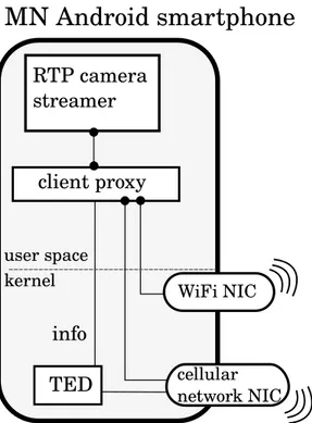
MN Android smartphone
RTP camera streamer client proxy cellular network NIC kernel TED info WiFi NIC user space4.2 Mobile node 33
As mentioned before, the MN is in practice an Android smartphone. I chose to use an LG Nexus 5 as a reference device since it ships out with the stock Android OS. On the top of the Operating System I chose to use a camera streamer application that periodically sends captured video frames to a remote relay. Also, such camera streamer application allows to specify the destination IP address and the destination port so that the local client proxy can be employed. In fact all the traffic originated by the application passes through the client proxy which in turn forwards all the packets to the relay. Both the application camera streamer and the client proxy reside in Android OS user space while the TED component should be built in the Android kernel. The MN design structure is shown in figure 4.1 and it is clearly a stack: the user interacts with the camera application which exchanges packets with the local client proxy. The latter interacts with the TED module and takes decisions about which NIC it should transmit from. Figure 4.2 outlines the Android software stack. System applications and user applications such as email clients, games, messaging apps, etc., rely on the Java API Framework. This also applies to many real-time and VoIP user applications. For this reason an RTP camera streamer built in Java has been chosen to be the real-time user application running on top of the Java API Framework stack layer. The client proxy instead directly resides on top of the Native C libraries stack layer. This choice comes from the fact that the original ABPS client proxy for GNU Linux distributions was implemented in C directly employing the GNU libc library. Thus, adapting the ABPS client proxy to the Android architecture does not require the Java API Framework. Moreover such proxy application is not intended to provide any user interaction facilities and the Java API Framework would only introduce needless complexity.
34 4. Project goals and design
4.2 Mobile node 35
The third ABPS component of interest that runs on the MN is the TED module which resides in the Linux Kernel layer. In particular TED is a soft-ware patch that modifies some of the linux kernel components such as the socket structure, the UDP message handler, the IP packet handler and the mac80211 kernel subsystem. The latter consists of driver APIs for 802.11 WiFi SoftMAC devices which are those network interfaces whose frame man-agement is expected to be done in software by the kernel[1]. In fact TED interacts with the mac80211 subsystem software part that handles frames transmission and frames delivery status providing data-link-layer informa-tion to the client proxy.
A similar feature makes use of the 802.11 frame ACK status to the appli-cation layer already exists in the Linux Kernel and can be employed through the SO WIFI STATUS socket option. This option was introduced because 802.1X EAPOL handshake implemented in hostapd requires knowing the delivery status of 802.11 frames[23]. However this option does not provide information about retransmissions and does not support packets fragmen-tation: if the application sends a transport layer packet that is big enough to be fragmented then the socket with the SO WIFI STATUS option enabled reports to the application the ack status of the first fragment only. On the contrary TED provides support for both retransmission information and packets fragmentation. In any case developing TED as an integration of the SO WIFI STATUSoption would be an interesting future work.
The main problem for these approaches is that most of the WiFi chips integrated in smartphones are of the FullMAC type thus implementing all the data-link-layer management in their firmwares. FullMAC wireless NICs do not support mac80211 and both TED and the SO WIFI STATUS option cannot be employed in this kind of WiFi chips. The choice of FullMAC NICs comes form the fact they allow smartphones’ processors to save power by of-floading certain operations such as association, authentication, scanning, etc. Also, most of the FullMAC NICs’ firmwares are closed source and directly maintained by chip vendors which do not allow any external modification.
36 4. Project goals and design
Figure 4.3: Picture of the MN device. An LG Nexus 5 smartphone with an USB WiFi dongle which integrates a Ralink RT2870 chipset.
While the authors of NexMon[81] disassembled and patched the closed source firmware of the Nexus 5 WiFi chip successfully enabling monitor mode, performing reverse engineering for many different chips guaranteeing a reli-able QoS is an obviously too difficult task and would introduce enormous complications. On the other hand open source firmwares are not expected to be released by WiFi chips vendors in the early future and a reverse engineer-ing approach for enablengineer-ing TED functionality in firmwares may be worth a try in future works. Hopefully, the spreading of this kind of works may convince chip vendors to release source code of their firmwares or at least provide a software interface able to access some information internally hold by these FullMAC chips. In any case I opted for an external USB WiFi dongle (figure
4.3) with a Ralink RT2879 chip which is of the SoftMAC type and supports the mac80211 subsystem.
4.3 Relay and Correspondent Node 37
This let me focus on developing the client proxy, enhancing the TED module and testing their behaviour. Moreover, fast vertical handover capabilities may also be advantageous in other contexts with less strict power consump-tion requirements and different hardware environments such as connected cars[9].
4.3 Relay and Correspondent Node
In order to deploy the MN described in the previous section in a practical scenario, other two components are required: the external relay and the CN. The external relay is required since I consider both the MN and the CN being behind NATs and firewalls as most of current end nodes are today. The idea was to develop a simple UDP relay application which listens on two UDP ports, one per end-node. If end nodes send an initialization datagram to the relay, the latter would be able to forward incoming datagrams in both directions and the MN and CN can bypass NATs and firewalls. It is important to remember that the MN is equipped with multiple NICs and may encounter network reconfigurations thus the relay may receive initialization messages from different source IP addresses and ports of the same MN. In this case the relay should store and continuously update all the current MN’s source IP addresses and ports in order to forward incoming traffic from the CN to all the MN’s active NICs. Moreover an authentication mechanism must be employed to avoid undesired forwarding to third-parties. Such authentication mechanism is out of the scope of this work but must be covered in future enhancements.
In this project the CN simply refers to the receiving counterpart of the MN. It should be able to send an initialization message to the external relay in order to be reachable since, like the MN, it resides behind a symmetric NAT and firewall. After the initialization phase the CN should simply listen to incoming RTP (over UDP) messages from the relay, decode the RTP stream, re-encode it into video frames and eventually storing them into an output
38 4. Project goals and design
file. The idea is to achieve a real-time video streaming service which would be easily extensible to a VoIP or videoconference service in future works.
Chapter 5
Project development
5.1 TED
In this section we will see in detail how TED works and how I contributed to its development.
5.1.1 Previous versions and working principles
Previous implementations of TED already existed for the Linux Kernel. After being developed by Vittorio Ghini and presented in 2011 as part of the ABPS architecture[53], it has been reviewed and modified several times as the Linux Kernel was evolving and being updated. The last working version of TED before my contribution was developed for version 4.0.1 of the Linux Kernel by Gabriele Di Bernardo and Alesssandro Mengoli in their bache-lor’s thesis works[54][52]. They introduced support for IPv6 and based the interlayer information passing mechanism on the sk buff kernel structure. Simplifying, an allocation of the sk buff structure contains the headers and the payload of a packet together with some additional information that the kernel may use to correctly manage it. We can then think of a direct re-lation between packets and sk buff structures. When a user space process sends a packet through a TCP or UDP socket, the kernel will create a new sk buff structure and link it to the transport layer header and the payload
![Figure 3.2: LISP data-packets encapsulation and decapsulation[42].](https://thumb-eu.123doks.com/thumbv2/123dokorg/7435610.99955/32.892.142.717.195.483/figure-lisp-data-packets-encapsulation-and-decapsulation.webp)
![Figure 3.3: Jingle signaling and media relaying[20].](https://thumb-eu.123doks.com/thumbv2/123dokorg/7435610.99955/37.892.155.746.160.560/figure-jingle-signaling-and-media-relaying.webp)
![Figure 3.4: Employment of a data relay to cope NATs and firewalls[53].](https://thumb-eu.123doks.com/thumbv2/123dokorg/7435610.99955/39.892.154.736.196.459/figure-employment-data-relay-cope-nats-firewalls.webp)
![Figure 3.5: The ABPS architecture[53].](https://thumb-eu.123doks.com/thumbv2/123dokorg/7435610.99955/41.892.155.735.185.446/figure-the-abps-architecture.webp)
![Figure 4.2: Android Platform Architecture[26]](https://thumb-eu.123doks.com/thumbv2/123dokorg/7435610.99955/48.892.140.718.197.1052/figure-android-platform-architecture.webp)

