IEEE Antennas and Propagation Magazine, Vol. 54, No. 4, August 2012 49 terials: Physics and Engineering Explorations, New York,
Wiley Interscience, 2006, pp. 57-77.
38. S. Maci, M. Caiazzo, A. Cucini, and M. Casaletti, “A Pole-Zero Matching Method for EBG Surfaces Composed of a Dipole FSS Printed on a Grounded Dielectric Slab,” IEEE Transactions on Antennas and Propagation, AP-53, 1, Janu ary 2005, pp. 70-81.
39. J. E. Raynolds, B. A. Munk, J. B. Pryor, and R. J. Marhefka, “Ohmic Loss in Frequency-Selective Surfaces,” Journal of Applied Physics, 93, 9, May 2003, pp. 5346-5358.
40. F. Costa, A. Monorchio, and G. Manara, “Analysis and Design of Ultra Thin Electromagnetic Absorbers Comprising Resistively Loaded High Impedance Surfaces,” IEEE Trans-actions on Antennas and Propagation, AP-58, 5, May 2010, pp. 1551-1558.
41. K. W. Whites and R. Mittra, “An Equivalent Boundary-Condition Model for Lossy Planar Periodic Structures at Low Frequencies,” IEEE Transactions on Antennas and Propaga-tion, AP-44, 12, 1996, pp. 1617-1628.
42. D. M. Pozar, Microwave Engineering, Second Edition, Toronto, John Wiley & Sons, 1998.
43. O. Luukkonen, C. Simovski, G. Granet, G. Goussetis, D. Lioubtchenko, A. V. Räisänen, and S. A. Tretyakov, “Simple and Accurate Analytical Model of Planar Grids and High-Impedance Surfaces Comprising Metal Strips or Patches,” IEEE Transactions on Antennas and Propagation, AP-56, 6, 2008, pp. 1624-1632.
44 . T. K. Wu, Frequency Selective Surface and Grid Array, New York, John Wiley & Sons, Inc., 1995.
45 . G. Manara, A. Monorchio, and R. Mittra, “Frequency Selective Surface Design Based on Genetic Algorithm,” Electronics Letters, 35, 17, August 1999, pp. 1400-1401. 46 . B. Hooberman, “Everything You Ever Wanted to Know About Frequency-Selective Surface Filters but Were Afraid to Ask,” Technical Report, Department of Physics, Columbia University.
47 . V. V. Yatsenko, S. A. Tretyakov, S. I. Maslovski, and A. A. Sochava, “Higher Order Impedance Boundary Conditions for Sparse Wire Grids,” IEEE Transactions on Antennas and Propagation, AP-48, 5, May 2000, pp. 720-727.
Feasibility of Body-Centric Systems
Using Passive Textile RFID Tags
S. Manzari, C. Occhiuzzi, and G. Marrocco
DISP - University of Roma Tor VergataVia del Politecnico, 1, 00133, Rome, Italy
E-mail: [email protected]; [email protected]; [email protected]
Abstract
Recent progresses in the design of wearable RFID-tag antennas stimulate the idea of passive body-centric systems, wherein the required power to drive the wearable tags is directly scavenged from the interrogation signal emitted by the reader unit. While active body-centric links have been extensively investigated, the feasibility of passive systems is still questionable, due to the poor sensitivity of the tags and due to the modest reading distances. This paper describes a systematic measurement campaign involving low-profi le wearable textile tags in the UHF RFID band. It was demonstrated that both on-body and off-body links are affordable, with a power budget fully compliant with the available technology and the safety standards. The experiments permitted identifying the most-effi cient tag placements, and proposing some quantitative and general guidelines useful to characterize and design this kind of new system.
Keywords: RFID; wearable; textile antenna; body-centric; on-body wireless network
1. Introduction
R
adio-Frequency Identifi cation (RFID) technology is increasingly being adopted in logistics, manufacturing, and security. Pioneering applications are currently being experimented with in sensor networks, personal healthcare, and even entertainment and social arts [1-6]. In these battery-less (say, passive) systems, the RF power required by the transponder element (the tag) to respond to the query device (the reader) is scavenged from the interrogation signal by the tag itself. Since passive RFID tags do not require regular recharging, they are suited to disposable usage, and to the per vasive and long-term distribution within environments.In some applications, the tag device – comprising an antenna integrated with a microchip transponder, and eventu-ally with additional sensors or actuators – needs to be worn on the human body [7-13]. Tags integrated into clothes could work as a body-centric passive RFID system, able to track people’s position and/or to monitor life parameters, all the time and everywhere. If compared with active body-centric systems, RFID solutions could furthermore offer a higher degree of pervasiveness, thanks to the already available low-cost radios, the absence of rechargeable local power sources, and, not least, to the forthcoming integration of RFID func-tions inside mass-diffused smart phones. While active
body-centric communications have been deeply addressed in the last decade [14-20], for that which concerns both the antenna design and the characterization of the propagation phenomena, passive wearable RFIDs have instead received much less attention, mainly restricted to the antenna design. These kind of systems deserve additional challenges, since RFID antennas do not transmit. Rather, the power received by the reader is backscattered from the RFID tag’s antenna. Hence, the RFID antennas need to achieve effi cient-energy scavenging in the presence of the very lossy human body, while keeping the antenna’s size small at the involved frequency (UHF: 866-970 MHz, including European, US, and Asia subbands).
As in more-mature active body-centric systems, interest-ing RFID communication modalities can involve on-body and off-body links. For example, the off-body communication could be useful for locating and monitoring people inside buildings, by means of fi xed readers placed in different rooms, or by a wearable reader and ambient-disseminated tags [21]. A possible application is access control in dangerous or restricted areas. The on-body communication is instead typical of unusual scenarios, where a fi xed communications infra-structure is missing. This could be the case of a sportsman, a soldier, or a fi reman equipped with different RFID sensors (inside a garment), interrogated by the user’s handheld stan-dard communicator in harsh environments [22, 23]. In both
types of link, the presence of the human body must be taken into account, in order to understand and reduce the phenomena of scattering and power absorption, and to evaluate compli ance with the international regulations on electromagnetic exposure and Specifi c Absorption Rate (SAR) limits [24, 25].
First experimental results may be found in [10, 11] con-cerning the identifi cation of runners in an outdoor area, also taking into account the shadowing effects in the case of for-mations or grouping. In [24], the power required to establish an RFID link with a human body during sleep movements of the limbs was investigated. Finally, some measurements of reading range for wearable tags placed onto the trunk and onto the arms may be found in [8], for the case of only steady pos-tures. However, no systematic study is available to support the power-budget design for on-body and off-body RFID systems.
Starting from our recent experience with wearable RFID tags [7, 8, 24], this paper discusses the feasibility of a body-centric system including passive RFID textile tags, derived from a previous Tefl on prototype. An articulated experimental campaign was aimed at understanding the achievable reading ranges, the minimum number of required tags, and their most suitable positions over the body for reliable on-body and off-body links. Human activity and shadowing effects were also taken into account, in order to understand the possibility of establishing robust and safe communications. Moreover, since some sensing and tracking applications are based on the proc-essing [26] of the power backscattered by the tag toward the reader, this quantity was measured and analyzed for interest ing postures and motion patterns.
Even if the results were expected to be strictly dependent on the specifi c environment and on the power consumption of the RFID microchip transponder, some useful normalizations were introduced, with the aim of providing fi rst-level guide-lines for the design of future passive body-centric networks.
2. Textile Slotted-Patch Antenna
The wearable antenna considered here for the experi-ments was originally proposed in [8]. It was basically a quar ter-wavelength patch, connected to the RFID microchip via a top H-slot, the shape factor of which was chosen to synthesize the required complex input impedance for microchip match ing. A textile version was adopted in this paper. The Tefl on substrate was replaced by a 3 mm-thick synthetic felt (Fig ure 1), and the conductors were made from carved adhesive copper. Due to the variability of manufacturing processes, the dielectric properties of the felt were not really assessed in the UHF band [14, 28, 29]. Hence, the electromagnetic features of our felt sample were experimentally evaluated by means of a specifi c parameter-identifi cation technique, involving numeri cal models and measurements on planar antennas. The result ing permittivity and conductivity at the European RFID fre quency of 870 MHz were ε =1.17 and σ = ×2 10 −4S/m, to be compared with the published values of ε =1.1 in [29] and ε =1.38, tanδ =0.0023
S/m in [30], both at 2.45 GHz. The antenna’s matching was referred to an NXP–G2X-TSSOP-8 [31] microchip transponder, with an impedance Zchip =15 135 − j Ω and a power sensitivity
15
chip
P = − dBm. The resulting fabricated prototype had and overall size of 7 cm × 9 cm and a weight of 7.5 g.
The electromagnetic performance of the tag has been experimentally characterized with respect to the realized gain,
ˆT T
G =G τ , i.e., the radiation gain, GT, of the tag’s antenna placed over the body, reduced by the power-transfer coeffi cient
1
τ ≤ between the tag’s antenna and the microchip. The realized gain was measured by means of the turn-on method [32], starting from the knowledge of the reader’s gain, GR; the reader-tag distance, d; the polarization mismatch, ηp, between the reader and the tag (here set to 1/2); and fi nally, the turn-on power, Pinto, e.g., the minimum input power required to be provided to the reader unit to force the remote microchip to send back its code:
2 0 ˆ 4 chip to R in T p P d G P G λπ η = . (1)
For this purpose, a UHF long-range reader, based on the ThingMagic M5-e ASIC [33], was used. The wearable tag was interrogated by means of a 6 dB circularly polarized patch antenna connected to the reader. The tag was placed on the torso of a volunteer, in front of the reader’s antenna, at 1.3 m from the ground. Ground refl ections were minimized by using absorbing panels (Figure 2).
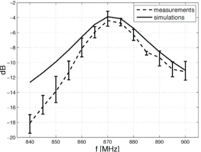
Figure 3 shows the frequency-dependent measured real-ized gain. Data were referred to the frontal direction, where the tag’s antenna and the reader’s antenna were aligned. The maximum gain at the reference frequency of 869 MHz in Europe, ranged between −5dB and −3dB, and was hence fully comparable to the Tefl on prototype in [8] (−4 dB<GˆT < −3 dB ). It is worth mentioning that nearly identical results were obtained when the tag was placed onto different body segments, such as the back and the arm.
Figure 1. A prototype of a textile wearable tag, made of felt and adhesive copper. The dimensions (in mm) were L =59,
80
W = , a =15, b =15, p =14, d =10, Lg =70, g =3,
3
hs = , Wg =90.
The textile antenna was then used to characterize some passive RFID body-centric channels in both off-body and on-body links.
3. Off-Body Communications
In off-body communications, the most-relevant parame-ters to consider are the reading range of the tag in a real
envi-ronment, depending on its position over the body, and the minimum number of tags and readers necessary to achieve a reliable interrogation of the subject.
The reading range of the wearable tag was measured according to the following body-centric procedure. It was defi nitely of interest to discriminate the region surrounding the tagged human body wherein with a reader placed any way, at least a tag was successfully interrogated. It was expected that such a region would depend on the position of the tag over the body and on the reader-emitted power, as well as on the reader antenna’s pattern. As for the previous Tefl on prototype in [8], the textile tag also revealed very little sensitivity to the body’s position in terms of impedance matching and maximum gain, thanks to the presence of the ground plane. Nevertheless, the shape of the reading region may be dependent on such a posi-tion, due to the specifi c shadowing caused by body segments themselves, and by absorption modality. Hence, to discuss this issue, three different tag placements were considered (front torso, arm, and back), each in horizontal and vertical orienta-tion, as shown in Figure 6.
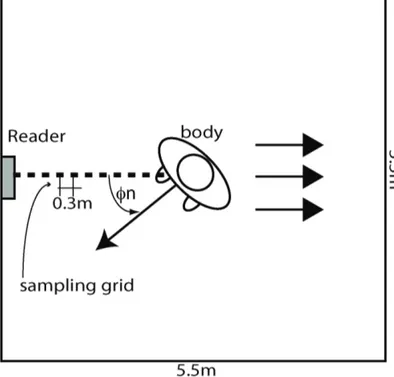
For the sake of simplicity, the reading region was meas-ured in a reciprocal way, e.g., the reader was fi xed in some location in the room, while the tagged person walked away from the reader along the boresight of the reader’s antenna (see Figure 4). The actual reader-body distance was consid ered to belong to the reading region of the tag if the tag was able to correctly reply to the reader’s interrogation. The pro cedure was repeated for rotations of the body of {0°, 90°, 180°, 270°} degrees with respect to the reader’s antenna.
The measurements were performed in a 5.5 m × 5.5 m × 3 m offi ce room, the inner furniture having been removed. The same reader’s antenna and long-range reader as before were placed on the middle of a side wall, 1.3 m from the fl oor. The reader emitted a fi xed power of 3.2 W EIRP, which is the maximum value allowed by the European regulations. The space sampling rate was 30 cm.
In general, the reading range in real environments was affected by the presence of walls and furniture in a way that was also dependent on the reader’s power and the microchip’s sensitivity. All of these issues were extensively addressed in [21], but it is useful to recall that in the case of low-gain tags – as for the wearable textile patch – the effect of the side walls of the room considered here could be neglected. Hence, the results in the following sections may be extended to different environments by introducing the two-ray correction terms as in [21].
An example of a measurement is given in Figure 5, where the solid dots indicate a successful interrogation of the tag when the person stood at that point. The empty circles instead represent a reading failure. By considering that the transition between the reading region and the unreachable region was not sharp due to the formation of diffraction fringes [21], the following metrics are assumed to defi ne the maximum reading distance, dmax n( )φ , in a given direction φ φ= n. The distance
( )
max n
d φ was calculated from the human body to the fi rst point Figure 2. The setup for measuring the tag’s realized gain,
comprising the reader, the volunteer, and the absorbing panels. Here, the antenna was placed at the center of the human torso.
Figure 3. The maximum realized gain for the wearable tag placed on the human torso, as measured along the tag’s boresight. The vertical segments give the data variability over repeated measurements.
IEEE Antennas and Propagation Magazine, Vol. 54, No. 4, August 2012 51 types of link, the presence of the human body must be taken
into account, in order to understand and reduce the phenomena of scattering and power absorption, and to evaluate compli ance with the international regulations on electromagnetic exposure and Specifi c Absorption Rate (SAR) limits [24, 25].
First experimental results may be found in [10, 11] con-cerning the identifi cation of runners in an outdoor area, also taking into account the shadowing effects in the case of for-mations or grouping. In [24], the power required to establish an RFID link with a human body during sleep movements of the limbs was investigated. Finally, some measurements of reading range for wearable tags placed onto the trunk and onto the arms may be found in [8], for the case of only steady pos-tures. However, no systematic study is available to support the power-budget design for on-body and off-body RFID systems.
Starting from our recent experience with wearable RFID tags [7, 8, 24], this paper discusses the feasibility of a body-centric system including passive RFID textile tags, derived from a previous Tefl on prototype. An articulated experimental campaign was aimed at understanding the achievable reading ranges, the minimum number of required tags, and their most suitable positions over the body for reliable on-body and off-body links. Human activity and shadowing effects were also taken into account, in order to understand the possibility of establishing robust and safe communications. Moreover, since some sensing and tracking applications are based on the proc-essing [26] of the power backscattered by the tag toward the reader, this quantity was measured and analyzed for interest ing postures and motion patterns.
Even if the results were expected to be strictly dependent on the specifi c environment and on the power consumption of the RFID microchip transponder, some useful normalizations were introduced, with the aim of providing fi rst-level guide-lines for the design of future passive body-centric networks.
2. Textile Slotted-Patch Antenna
The wearable antenna considered here for the experi-ments was originally proposed in [8]. It was basically a quar ter-wavelength patch, connected to the RFID microchip via a top H-slot, the shape factor of which was chosen to synthesize the required complex input impedance for microchip match ing. A textile version was adopted in this paper. The Tefl on substrate was replaced by a 3 mm-thick synthetic felt (Fig ure 1), and the conductors were made from carved adhesive copper. Due to the variability of manufacturing processes, the dielectric properties of the felt were not really assessed in the UHF band [14, 28, 29]. Hence, the electromagnetic features of our felt sample were experimentally evaluated by means of a specifi c parameter-identifi cation technique, involving numeri cal models and measurements on planar antennas. The result ing permittivity and conductivity at the European RFID fre quency of 870 MHz were ε =1.17 and σ = ×2 10 −4S/m, to be compared with the published values of ε =1.1 in [29] and ε =1.38, tanδ =0.0023
S/m in [30], both at 2.45 GHz. The antenna’s matching was referred to an NXP–G2X-TSSOP-8 [31] microchip transponder, with an impedance Zchip =15 135 − j Ω and a power sensitivity
15
chip
P = − dBm. The resulting fabricated prototype had and overall size of 7 cm × 9 cm and a weight of 7.5 g.
The electromagnetic performance of the tag has been experimentally characterized with respect to the realized gain,
ˆT T
G =G τ , i.e., the radiation gain, GT, of the tag’s antenna placed over the body, reduced by the power-transfer coeffi cient
1
τ ≤ between the tag’s antenna and the microchip. The realized gain was measured by means of the turn-on method [32], starting from the knowledge of the reader’s gain, GR; the reader-tag distance, d; the polarization mismatch, ηp, between the reader and the tag (here set to 1/2); and fi nally, the turn-on power, Pinto, e.g., the minimum input power required to be provided to the reader unit to force the remote microchip to send back its code:
2 0 ˆ 4 chip to R in T p P d G P G λπ η = . (1)
For this purpose, a UHF long-range reader, based on the ThingMagic M5-e ASIC [33], was used. The wearable tag was interrogated by means of a 6 dB circularly polarized patch antenna connected to the reader. The tag was placed on the torso of a volunteer, in front of the reader’s antenna, at 1.3 m from the ground. Ground refl ections were minimized by using absorbing panels (Figure 2).
Figure 3 shows the frequency-dependent measured real-ized gain. Data were referred to the frontal direction, where the tag’s antenna and the reader’s antenna were aligned. The maximum gain at the reference frequency of 869 MHz in Europe, ranged between −5dB and −3dB, and was hence fully comparable to the Tefl on prototype in [8] (−4 dB<GˆT < −3 dB ). It is worth mentioning that nearly identical results were obtained when the tag was placed onto different body segments, such as the back and the arm.
Figure 1. A prototype of a textile wearable tag, made of felt and adhesive copper. The dimensions (in mm) were L =59,
80
W = , a =15, b =15, p =14, d =10, Lg =70, g =3,
3
hs = , Wg =90.
The textile antenna was then used to characterize some passive RFID body-centric channels in both off-body and on-body links.
3. Off-Body Communications
In off-body communications, the most-relevant parame-ters to consider are the reading range of the tag in a real
envi-ronment, depending on its position over the body, and the minimum number of tags and readers necessary to achieve a reliable interrogation of the subject.
The reading range of the wearable tag was measured according to the following body-centric procedure. It was defi nitely of interest to discriminate the region surrounding the tagged human body wherein with a reader placed any way, at least a tag was successfully interrogated. It was expected that such a region would depend on the position of the tag over the body and on the reader-emitted power, as well as on the reader antenna’s pattern. As for the previous Tefl on prototype in [8], the textile tag also revealed very little sensitivity to the body’s position in terms of impedance matching and maximum gain, thanks to the presence of the ground plane. Nevertheless, the shape of the reading region may be dependent on such a posi-tion, due to the specifi c shadowing caused by body segments themselves, and by absorption modality. Hence, to discuss this issue, three different tag placements were considered (front torso, arm, and back), each in horizontal and vertical orienta-tion, as shown in Figure 6.
For the sake of simplicity, the reading region was meas-ured in a reciprocal way, e.g., the reader was fi xed in some location in the room, while the tagged person walked away from the reader along the boresight of the reader’s antenna (see Figure 4). The actual reader-body distance was consid ered to belong to the reading region of the tag if the tag was able to correctly reply to the reader’s interrogation. The pro cedure was repeated for rotations of the body of {0°, 90°, 180°, 270°} degrees with respect to the reader’s antenna.
The measurements were performed in a 5.5 m × 5.5 m × 3 m offi ce room, the inner furniture having been removed. The same reader’s antenna and long-range reader as before were placed on the middle of a side wall, 1.3 m from the fl oor. The reader emitted a fi xed power of 3.2 W EIRP, which is the maximum value allowed by the European regulations. The space sampling rate was 30 cm.
In general, the reading range in real environments was affected by the presence of walls and furniture in a way that was also dependent on the reader’s power and the microchip’s sensitivity. All of these issues were extensively addressed in [21], but it is useful to recall that in the case of low-gain tags – as for the wearable textile patch – the effect of the side walls of the room considered here could be neglected. Hence, the results in the following sections may be extended to different environments by introducing the two-ray correction terms as in [21].
An example of a measurement is given in Figure 5, where the solid dots indicate a successful interrogation of the tag when the person stood at that point. The empty circles instead represent a reading failure. By considering that the transition between the reading region and the unreachable region was not sharp due to the formation of diffraction fringes [21], the following metrics are assumed to defi ne the maximum reading distance, dmax n( )φ , in a given direction φ φ= n. The distance
( )
max n
d φ was calculated from the human body to the fi rst point Figure 2. The setup for measuring the tag’s realized gain,
comprising the reader, the volunteer, and the absorbing panels. Here, the antenna was placed at the center of the human torso.
Figure 3. The maximum realized gain for the wearable tag placed on the human torso, as measured along the tag’s boresight. The vertical segments give the data variability over repeated measurements.
of faulty interrogation (empty circle) followed by less than two consecutive points of suc cessful interrogation (fi lled circles). In other words, we gave a positive value to even the very isolated failure points, in con sideration that the subject could be moving and so the subject could still be statistically detected with overall continuity.
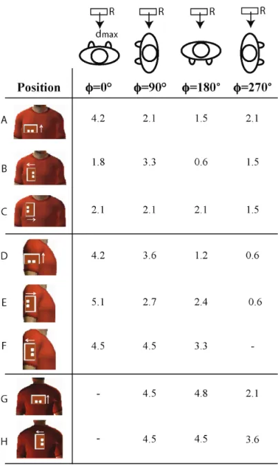
The results of the measurement campaign are presented in a compact form in Figure 6. The overall maximum reading distance was about 5 m, arising in Case E (with the tag over the arms with horizontal orientation). In most of the confi gu-rations considered, the maximum distance was about 4.5 m, confi rming that the maximum gain of the antenna had very little sensitivity to the position over the body. The reading distances out of the antenna’s boresight were instead depend-ent on the dielectric losses of the human body, which pro duced signifi cant absorption and shadowing, especially in the case of tags placed on the shoulder. The polarization of the tag, e.g., the orientation of the radiating edge of the patch, seemed to play a signifi cant role in the achievable reading ranges, even if the physical reasons were not immediately clear. Vertical polarization performed far better in the case of placement over the chest, while horizontal polarization appeared more suitable for placement over shoulders and arms.
However, in none of the considered tag placements was it possible to achieve a nearly uniform coverage with just a sin-gle tag. However, by a combined use of tags it was expected to achieve a reliable RFID link, for instance, by placing one tag over the torso and the other over the back (A+H), or instead, a single tag for each arm (F(right) + F(left)). The combined results are shown in Figure 7, where nearly circular body-centric interrogation regions were visible. These dia grams represented the area in which wherever a reader emit ting 3.2 W EIRP is Figure 4. The reader-tag mutual orientations during
measurements to evaluate the extension of the body-centric reading region. The volunteer equipped with a wearable tag walked away from the reader’s antenna, which was placed on the middle of a wall inside a 5.5 m × 5.5 m × 3 m room, at a distance of 1.3 m from the fl oor. The tag was interrogated when the volunteer was standing at the dotted positions, in 30 cm steps. Each point was said to be acces sible by the RFID system if the tag was able to answer the reader. The experiment was repeated for four orientations of the body with respect to the reader’s antenna, e.g., for
{0 , 90 , 1 80 , 270 }
n
ϕ = ° ° ° ° , to collect the two-dimensional reading range.
Figure 5. An example of the reading-region measurements when the tag was placed over the torso with vertical polarization. For each readerbody orientation, a fi lled circle indicates a successful reading of the tag at that point, while an empty circle indicates a reading failure. The maximum reading distance, dmax, along each direction was calculated from the human body to the fi rst point of fault interrogation followed by less than two consecutive points of successful interrogation.
Figure 6. The reading distances (in meters) measured at four different angles from the thorax’s normal axis, for several positions and orientations of the body-worn tag.
placed in front of the person, it was possi ble to monitor the subject independently of the subject’s posi tion and orientation. Even better results may be achieved by using three tags: two of them over both of the arms, and one over the chest.
In conclusion, a single reader permits establishing a reli-able RFID link with a person equipped with two or three tags within a room of size 4 m by 4 m. Four readers, each placed on each side wall, would instead enable continuous interroga tion within a room that was four times larger (9 m by 9 m).
The above results were obtained for a particular choice of the reader’s power and of the family of microchips. However, such data can also be useful in case of different choices of power parameters by introducing the effective microchip’s sensitivity [21], an aggregate performance indicator for the tag, defi ned as
ˆ chip chip T P p G = . (2)
Figure 7. The body-centric reading regions for two cou plets of tags placed on the human body: (top) tags over the front torso and shoulders (Cases A and H in Figure 6); (bottom) tags over both of the arms (Case F in Figure 6). The continuous and dashed arrows indicate the maximum reading distances, dmax n( )φ , of the two tags in the specifi c direction, and the ellipse-like region gives the estimate of the overall resulting body-centric reading region for the combined two-tag system.
This gives the minimum radio-frequency power that the tag has to collect to exhibit the same averaged free-space reading distance as a perfectly matched tag placed over a lossless object (averaged G =ˆT 1). In our particular case, pchip,0 =90µW.
From Equation (1), the maximum reading distance is linearly dependent on the ratio EIRP G PˆT chip , where EIRP G P= R in
. Therefore, for a different choice of power and effective microchip sensitivity, an estimation of the reading range,
max chip EIRP d P
, may be roughly deduced from the values of the
reading distances given in Figure 6 (now denoted as dmax,0 for 0 3.2
IEEE Antennas and Propagation Magazine, Vol. 54, No. 4, August 2012 53 of faulty interrogation (empty circle) followed by less than two
consecutive points of suc cessful interrogation (fi lled circles). In other words, we gave a positive value to even the very isolated failure points, in con sideration that the subject could be moving and so the subject could still be statistically detected with overall continuity.
The results of the measurement campaign are presented in a compact form in Figure 6. The overall maximum reading distance was about 5 m, arising in Case E (with the tag over the arms with horizontal orientation). In most of the confi gu-rations considered, the maximum distance was about 4.5 m, confi rming that the maximum gain of the antenna had very little sensitivity to the position over the body. The reading distances out of the antenna’s boresight were instead depend-ent on the dielectric losses of the human body, which pro duced signifi cant absorption and shadowing, especially in the case of tags placed on the shoulder. The polarization of the tag, e.g., the orientation of the radiating edge of the patch, seemed to play a signifi cant role in the achievable reading ranges, even if the physical reasons were not immediately clear. Vertical polarization performed far better in the case of placement over the chest, while horizontal polarization appeared more suitable for placement over shoulders and arms.
However, in none of the considered tag placements was it possible to achieve a nearly uniform coverage with just a sin-gle tag. However, by a combined use of tags it was expected to achieve a reliable RFID link, for instance, by placing one tag over the torso and the other over the back (A+H), or instead, a single tag for each arm (F(right) + F(left)). The combined results are shown in Figure 7, where nearly circular body-centric interrogation regions were visible. These dia grams represented the area in which wherever a reader emit ting 3.2 W EIRP is Figure 4. The reader-tag mutual orientations during
measurements to evaluate the extension of the body-centric reading region. The volunteer equipped with a wearable tag walked away from the reader’s antenna, which was placed on the middle of a wall inside a 5.5 m × 5.5 m × 3 m room, at a distance of 1.3 m from the fl oor. The tag was interrogated when the volunteer was standing at the dotted positions, in 30 cm steps. Each point was said to be acces sible by the RFID system if the tag was able to answer the reader. The experiment was repeated for four orientations of the body with respect to the reader’s antenna, e.g., for
{0 , 90 , 1 80 , 270 }
n
ϕ = ° ° ° ° , to collect the two-dimensional reading range.
Figure 5. An example of the reading-region measurements when the tag was placed over the torso with vertical polarization. For each readerbody orientation, a fi lled circle indicates a successful reading of the tag at that point, while an empty circle indicates a reading failure. The maximum reading distance, dmax, along each direction was calculated from the human body to the fi rst point of fault interrogation followed by less than two consecutive points of successful interrogation.
Figure 6. The reading distances (in meters) measured at four different angles from the thorax’s normal axis, for several positions and orientations of the body-worn tag.
placed in front of the person, it was possi ble to monitor the subject independently of the subject’s posi tion and orientation. Even better results may be achieved by using three tags: two of them over both of the arms, and one over the chest.
In conclusion, a single reader permits establishing a reli-able RFID link with a person equipped with two or three tags within a room of size 4 m by 4 m. Four readers, each placed on each side wall, would instead enable continuous interroga tion within a room that was four times larger (9 m by 9 m).
The above results were obtained for a particular choice of the reader’s power and of the family of microchips. However, such data can also be useful in case of different choices of power parameters by introducing the effective microchip’s sensitivity [21], an aggregate performance indicator for the tag, defi ned as
ˆ chip chip T P p G = . (2)
Figure 7. The body-centric reading regions for two cou plets of tags placed on the human body: (top) tags over the front torso and shoulders (Cases A and H in Figure 6); (bottom) tags over both of the arms (Case F in Figure 6). The continuous and dashed arrows indicate the maximum reading distances, dmax n( )φ , of the two tags in the specifi c direction, and the ellipse-like region gives the estimate of the overall resulting body-centric reading region for the combined two-tag system.
This gives the minimum radio-frequency power that the tag has to collect to exhibit the same averaged free-space reading distance as a perfectly matched tag placed over a lossless object (averaged G =ˆT 1). In our particular case, pchip,0 =90µW.
From Equation (1), the maximum reading distance is linearly dependent on the ratio EIRP G PˆT chip , where EIRP G P= R in
. Therefore, for a different choice of power and effective microchip sensitivity, an estimation of the reading range,
max chip EIRP d P
, may be roughly deduced from the values of the
reading distances given in Figure 6 (now denoted as dmax,0 for 0 3.2
,0 ,0 0 chip max max chip chip P EIRP EIRP d d P EIRP P = (3) 5.3 10 3 max,0 chip EIRPd P − = × .
4. On-Body Communications
In case of on-body communications, in addition to the tag placements it is of interest to also analyze the effects of body posture and activity on link shadowing. Depending on the reader-tag position, different propagation phenomena are excited [34]. Creeping waves can be predominant for commu-nications between adjacent body segments (waist-torso, arm-forearm), while diffracted and refl ected free-space waves could be considered responsible for the communications between distant regions, such as arm-leg, head-waist, etc. In both cases, it is not appropriate to consider the typical far-fi eld approximation. The quality of the established links can hence be characterized according to the turn-on power, Pinto, ena bling the activation of the tag in the specifi c position, and according to the percentage of successfully interrogations. In order to provide a general performance indicator such as Equation (2), the turn-on power is here normalized by the microchip’s effective sensitivity, Pchip:
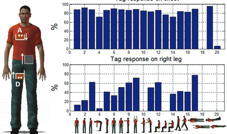
Figure 8. The antenna positions on the body. Five different links were considered here. The reader was placed at the waist, slightly on the left.
Figure 9. The postures assumed by the subject during the measurements. In the fi rst set of fourteen confi gurations, the subject stood or sat according to typical human activi ties. Two postures (15 and 16) were in motion. In the last set of four postures, the subjects laid on the fl oor, simu lating healthy and pathological conditions, such as the later safety position (LSP).
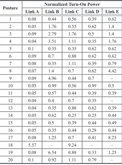
Table 1. The normalized turn-on powers, pto, for the postures in Figure 9 and the on-body RFID links in Figure 8.
Posture Normalized Turn-On Power
Link A Link B Link C Link D Link E 1 0.08 0.44 0.56 0.39 0.62 2 0.05 1.76 0.55 0.62 1.4 3 0.09 2.79 1.76 0.5 1.4 4 0.04 3.51 1.11 0.35 1.76 5 0.1 0.35 0.35 0.62 0.62 6 0.09 0.7 0.88 0.62 0.62 7 0.08 0.35 1.11 0.39 0.79 8 0.07 1.4 0.7 0.62 4.42 9 0.09 4.96 0.44 0.7 – 10 0.05 0.99 0.56 0.99 0.5 11 0.05 0.57 0.44 0.39 0.39 12 0.04 0.4 0.7 0.35 – 13 0.04 0.35 0.88 0.62 0.39 14 0.05 0.62 0.25 0.25 0.44 15 0.05 0.5 0.39 0.44 0.49 16 0.05 0.35 0.44 0.28 0.44 17 0.08 1.25 0.7 0.41 8.23 18 5.57 – 9.24 – – 19 0.08 6.54 0.88 0.33 1.25 20 0.1 0.92 1.11 0.79 – 3 10 into to chip P p P − = . (4)
Such a parameter could hence be considered as a kind of “transfer function” of the system: the lower pto, the more effi cient and reliable is the link.
In this second measurement campaign, the reader’s antenna was a smaller, linearly polarized, quarter-lambda patch (PIFA), with a maximum 3.3 dB gain, that was suited for placement onto the volunteer’s body, close to the waist. The reader unit was also attached onto the body (Figure 8).
The PIFA interrogated fi ve wearable tags, attached onto the torso, arm, head, leg, and wrist, respectively. To improve polarization matching, the PIFA was oriented so that its polarization vector was always parallel to that of the tags in all the experiments. During the measurements, the volunteer took twenty different “static” (1-14) and “moving” (15-16) pos tures, illustrated in Figure 9. The last four positions corre sponded to the subject lying on the ground and could be repre sentative of particularly dangerous situations, such as fainting or accidents.
The measurement results are reported in Table 1. In our specifi c case, by considering the same microchip sensitivity as
before, the turn-on power ranged between 8 dBm, corre-sponding to p =to 0.07 for Link A, and 29 dBm (p =to 9.24), for Link C. As expected, thanks to the smallest and stable dis-tance, the most-effi cient link was that involving the tag over the front torso (Link A). Independently of the different pos tures and movements, Link A required the minimum activa tion power, and it was only a little sensitive to the shadowing effects of the body. Link E (waist-wrist) was instead the most sensitive to the mismatch polarization and to the shadowing produced by body movements: in Postures 9 and 12, the tag placed on the wrist resulted in being even unreadable. Among the prone positions, recumbent Posture 18 was the most chal lenging position in which to establish an RFID link, due to the close presence of the ground within the reader-tag link. In this case, the required turn-on power was two orders of magnitude higher than in case of the standing positions. It is moreover worth observing that the two side-lying postures (19 and 20) yielded completely different turn-on powers, due to the asymmetric position of the reader/ tags over the body, and due to the combined shadowing effects of fl oor and arms.
Some statistics are presented, having performed NT inter-rogations of Tags A and D in the 20 postures with a fi xed reader power of P =in 20dBm, such that at least the Links A, D were fully active.
IEEE Antennas and Propagation Magazine, Vol. 54, No. 4, August 2012 55 ,0 ,0 0 chip max max chip chip P EIRP EIRP d d P EIRP P = (3) 5.3 10 3 max,0 chip EIRPd P − = × .
4. On-Body Communications
In case of on-body communications, in addition to the tag placements it is of interest to also analyze the effects of body posture and activity on link shadowing. Depending on the reader-tag position, different propagation phenomena are excited [34]. Creeping waves can be predominant for commu-nications between adjacent body segments (waist-torso, arm-forearm), while diffracted and refl ected free-space waves could be considered responsible for the communications between distant regions, such as arm-leg, head-waist, etc. In both cases, it is not appropriate to consider the typical far-fi eld approximation. The quality of the established links can hence be characterized according to the turn-on power, Pinto, ena bling the activation of the tag in the specifi c position, and according to the percentage of successfully interrogations. In order to provide a general performance indicator such as Equation (2), the turn-on power is here normalized by the microchip’s effective sensitivity, Pchip:
Figure 8. The antenna positions on the body. Five different links were considered here. The reader was placed at the waist, slightly on the left.
Figure 9. The postures assumed by the subject during the measurements. In the fi rst set of fourteen confi gurations, the subject stood or sat according to typical human activi ties. Two postures (15 and 16) were in motion. In the last set of four postures, the subjects laid on the fl oor, simu lating healthy and pathological conditions, such as the later safety position (LSP).
Table 1. The normalized turn-on powers, pto, for the postures in Figure 9 and the on-body RFID links in Figure 8.
Posture Normalized Turn-On Power
Link A Link B Link C Link D Link E 1 0.08 0.44 0.56 0.39 0.62 2 0.05 1.76 0.55 0.62 1.4 3 0.09 2.79 1.76 0.5 1.4 4 0.04 3.51 1.11 0.35 1.76 5 0.1 0.35 0.35 0.62 0.62 6 0.09 0.7 0.88 0.62 0.62 7 0.08 0.35 1.11 0.39 0.79 8 0.07 1.4 0.7 0.62 4.42 9 0.09 4.96 0.44 0.7 – 10 0.05 0.99 0.56 0.99 0.5 11 0.05 0.57 0.44 0.39 0.39 12 0.04 0.4 0.7 0.35 – 13 0.04 0.35 0.88 0.62 0.39 14 0.05 0.62 0.25 0.25 0.44 15 0.05 0.5 0.39 0.44 0.49 16 0.05 0.35 0.44 0.28 0.44 17 0.08 1.25 0.7 0.41 8.23 18 5.57 – 9.24 – – 19 0.08 6.54 0.88 0.33 1.25 20 0.1 0.92 1.11 0.79 – 3 10 into to chip P p P − = . (4)
Such a parameter could hence be considered as a kind of “transfer function” of the system: the lower pto, the more effi cient and reliable is the link.
In this second measurement campaign, the reader’s antenna was a smaller, linearly polarized, quarter-lambda patch (PIFA), with a maximum 3.3 dB gain, that was suited for placement onto the volunteer’s body, close to the waist. The reader unit was also attached onto the body (Figure 8).
The PIFA interrogated fi ve wearable tags, attached onto the torso, arm, head, leg, and wrist, respectively. To improve polarization matching, the PIFA was oriented so that its polarization vector was always parallel to that of the tags in all the experiments. During the measurements, the volunteer took twenty different “static” (1-14) and “moving” (15-16) pos tures, illustrated in Figure 9. The last four positions corre sponded to the subject lying on the ground and could be repre sentative of particularly dangerous situations, such as fainting or accidents.
The measurement results are reported in Table 1. In our specifi c case, by considering the same microchip sensitivity as
before, the turn-on power ranged between 8 dBm, corre-sponding to p =to 0.07 for Link A, and 29 dBm (p =to 9.24), for Link C. As expected, thanks to the smallest and stable dis-tance, the most-effi cient link was that involving the tag over the front torso (Link A). Independently of the different pos tures and movements, Link A required the minimum activa tion power, and it was only a little sensitive to the shadowing effects of the body. Link E (waist-wrist) was instead the most sensitive to the mismatch polarization and to the shadowing produced by body movements: in Postures 9 and 12, the tag placed on the wrist resulted in being even unreadable. Among the prone positions, recumbent Posture 18 was the most chal lenging position in which to establish an RFID link, due to the close presence of the ground within the reader-tag link. In this case, the required turn-on power was two orders of magnitude higher than in case of the standing positions. It is moreover worth observing that the two side-lying postures (19 and 20) yielded completely different turn-on powers, due to the asymmetric position of the reader/ tags over the body, and due to the combined shadowing effects of fl oor and arms.
Some statistics are presented, having performed NT inter-rogations of Tags A and D in the 20 postures with a fi xed reader power of P =in 20dBm, such that at least the Links A, D were fully active.
If the reader received NR responses from the tag, a qual-ity parameter was the percentage of answers, α , defi ned as
100 T
R
N N
α = . (5)
The reader was set to perform nine polls per second, each interrogation period was 10 s, and hence N =T 90. Both verti-cal and horizontal tag orientations were considered, and, as above, the PIFA was properly rotated to preserve the polariza-tion matching. The results are shown in Figure 10 and Fig ure 11 for the vertical and horizontal orientations of the anten nas.
Link A was rather robust, with a percentage of correct answers exceeding 70% in almost every case. Link D was instead much more sensitive to the human’s activity, with a lower percentage of answers, sometimes close to zero. The mutual orientation between the reader’s antenna and the wear-able tags affected the reliability of the links. It was apparent that Link A exhibited the best performance in the case of the vertical-polarization setup, since both the reader’s antenna and the tag were oriented along the directions of maximum radia tion, e.g., the radiating edges of the two patches were facing each other. For the same effect as before, Link D instead appeared to be the better performing link in the case of hori zontal polarization.
In any case, the lying positions were the most reliable, due to the high variability of the body segments’ positions. Except for the supine posture, the statistics of the readings could be very unstable in the other confi gurations, regardless of the required activation power. In these cases, the torso-waist channel results were also the most effi cient.
5. Measurement of Backscattered Power
The on-body confi gurations A, D, and E are here also characterized in terms of the backscattered power, PBS, received by the reader. This quantity is in general less critical than the turn-on power in view of estimating the quality of the RFID link, since the communication bottleneck is the forward link. Nevertheless, there are some emerging applications wherein the variation of the backscattered power is correlated to some physical property of the tag, and, in turn, to the change of the tagged object or of the nearby environment, with the purpose of achieving a sort of RFID passive sensing. This is the case when the tag is coupled to a chemically sensitive substrate detecting the presence of gases, or when the antenna itself is deformed by motion [35].
For this purpose, three rather common postures of on-body communication were considered, with the aim of ana-lyzing the expected fl uctuations of the received signals and an eventual correlation with the periodicity of motion. In the fi rst posture, the subject stood up motionless, as in Figure 9. In the second posture, the person instead walked along a straight path, inside a corridor, with controlled steps: fi rst a slow walk (60 cm/s per second) and then a faster motion (120 cm/s). In the
third posture, the subject folded his or her arms up and down, as shown in the inset to Figure 14. The same reader and PIFA antenna as before were used in the three experiments. The input power to the reader’s antenna was fi xed at P =in 20dBm. The backscattered power was deduced from the RSSI (received-signal strength indicator) provided by the reader, by means of the following conversion equation (spe cifi c for that reader):
0.8 96 0.8
BS LNA th
P = RSSI+ −G − − RSSI , (6)
with RSSI =th 48, and GLNA being the gain of the low-noise signal amplifi er, defi ned in the communication register. For generality, the backscattered power was normalized by the input power: BS BS in P p P = . (7)
Figure 12 shows that the fl uctuation of pBS for both the links were comparable, and were of the order of ±1dB around the average value. This uncertainty needs to be carefully taken into account in estimating the dynamic range of any sensing application based on RSSI processing.
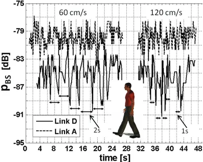
The measurements in for the walking case (Figure 13) showed that the motion affected the two links in a different way. While Link A (with the tag on the chest) remained approximately oscillating around the same average value, but with higher fl uctuations (±2dB), the backscattered power for Link D (with the tag on the leg) presented a much higher vari ability, due to the time-changing mutual position between the leg and the reader’s antenna. In this case, the amplitude of the fl uctuations was ±4dB, and they followed the walking rhythm. The period in the fi rst part of the trace was approxi mately 2 s, corresponding to a complete movement of the tagged leg at 60 cm/s, and which then changed to 1 s in the second trace, when the walker’s speed doubled.
In the same way, Link E was characterized during peri odic movements of the arm. Figure 14 shows the fl uctuation of the
BS
p in the case of a 2 s motion periodicity. When the arm was outstretched (parallel to the body), the reader correctly detected the backscattered power. In the case where the arm was folded (orthogonal to the reader), the microchip did not receive enough power to activate, and no signal was detected at the reader’s side. Hence, a cluster-like response was observed, with the clear possibility of recognizing the perio dicity of the motion.
From these results, it was apparent that the use of back-scattered power to retrieve the output of an RFID sensor looked very challenging for links involving moving limbs, since the theoretical dynamic range of the sensing mechanism had to be much larger than 8 dB to be recognized by the reader. Nevertheless, it was evident that the RSSI may be used as an indicator of motion of a specifi c part of the body. This could be attractive in itself for collecting statistics about repeated movements of working people, and for remote healthcare of elders.
Figure 10. The channel reliability, α , for several postures, expressed in terms of the percentage of answers with the antennas in vertical polarization.
IEEE Antennas and Propagation Magazine, Vol. 54, No. 4, August 2012 57 If the reader received NR responses from the tag, a
qual-ity parameter was the percentage of answers, α , defi ned as
100 T
R
N N
α = . (5)
The reader was set to perform nine polls per second, each interrogation period was 10 s, and hence N =T 90. Both verti-cal and horizontal tag orientations were considered, and, as above, the PIFA was properly rotated to preserve the polariza-tion matching. The results are shown in Figure 10 and Fig ure 11 for the vertical and horizontal orientations of the anten nas.
Link A was rather robust, with a percentage of correct answers exceeding 70% in almost every case. Link D was instead much more sensitive to the human’s activity, with a lower percentage of answers, sometimes close to zero. The mutual orientation between the reader’s antenna and the wear-able tags affected the reliability of the links. It was apparent that Link A exhibited the best performance in the case of the vertical-polarization setup, since both the reader’s antenna and the tag were oriented along the directions of maximum radia tion, e.g., the radiating edges of the two patches were facing each other. For the same effect as before, Link D instead appeared to be the better performing link in the case of hori zontal polarization.
In any case, the lying positions were the most reliable, due to the high variability of the body segments’ positions. Except for the supine posture, the statistics of the readings could be very unstable in the other confi gurations, regardless of the required activation power. In these cases, the torso-waist channel results were also the most effi cient.
5. Measurement of Backscattered Power
The on-body confi gurations A, D, and E are here also characterized in terms of the backscattered power, PBS, received by the reader. This quantity is in general less critical than the turn-on power in view of estimating the quality of the RFID link, since the communication bottleneck is the forward link. Nevertheless, there are some emerging applications wherein the variation of the backscattered power is correlated to some physical property of the tag, and, in turn, to the change of the tagged object or of the nearby environment, with the purpose of achieving a sort of RFID passive sensing. This is the case when the tag is coupled to a chemically sensitive substrate detecting the presence of gases, or when the antenna itself is deformed by motion [35].
For this purpose, three rather common postures of on-body communication were considered, with the aim of ana-lyzing the expected fl uctuations of the received signals and an eventual correlation with the periodicity of motion. In the fi rst posture, the subject stood up motionless, as in Figure 9. In the second posture, the person instead walked along a straight path, inside a corridor, with controlled steps: fi rst a slow walk (60 cm/s per second) and then a faster motion (120 cm/s). In the
third posture, the subject folded his or her arms up and down, as shown in the inset to Figure 14. The same reader and PIFA antenna as before were used in the three experiments. The input power to the reader’s antenna was fi xed at P =in 20dBm. The backscattered power was deduced from the RSSI (received-signal strength indicator) provided by the reader, by means of the following conversion equation (spe cifi c for that reader):
0.8 96 0.8
BS LNA th
P = RSSI+ −G − − RSSI , (6)
with RSSI =th 48, and GLNA being the gain of the low-noise signal amplifi er, defi ned in the communication register. For generality, the backscattered power was normalized by the input power: BS BS in P p P = . (7)
Figure 12 shows that the fl uctuation of pBS for both the links were comparable, and were of the order of ±1dB around the average value. This uncertainty needs to be carefully taken into account in estimating the dynamic range of any sensing application based on RSSI processing.
The measurements in for the walking case (Figure 13) showed that the motion affected the two links in a different way. While Link A (with the tag on the chest) remained approximately oscillating around the same average value, but with higher fl uctuations (±2dB), the backscattered power for Link D (with the tag on the leg) presented a much higher vari ability, due to the time-changing mutual position between the leg and the reader’s antenna. In this case, the amplitude of the fl uctuations was ±4dB, and they followed the walking rhythm. The period in the fi rst part of the trace was approxi mately 2 s, corresponding to a complete movement of the tagged leg at 60 cm/s, and which then changed to 1 s in the second trace, when the walker’s speed doubled.
In the same way, Link E was characterized during peri odic movements of the arm. Figure 14 shows the fl uctuation of the
BS
p in the case of a 2 s motion periodicity. When the arm was outstretched (parallel to the body), the reader correctly detected the backscattered power. In the case where the arm was folded (orthogonal to the reader), the microchip did not receive enough power to activate, and no signal was detected at the reader’s side. Hence, a cluster-like response was observed, with the clear possibility of recognizing the perio dicity of the motion.
From these results, it was apparent that the use of back-scattered power to retrieve the output of an RFID sensor looked very challenging for links involving moving limbs, since the theoretical dynamic range of the sensing mechanism had to be much larger than 8 dB to be recognized by the reader. Nevertheless, it was evident that the RSSI may be used as an indicator of motion of a specifi c part of the body. This could be attractive in itself for collecting statistics about repeated movements of working people, and for remote healthcare of elders.
Figure 10. The channel reliability, α , for several postures, expressed in terms of the percentage of answers with the antennas in vertical polarization.
6. Safety Issues
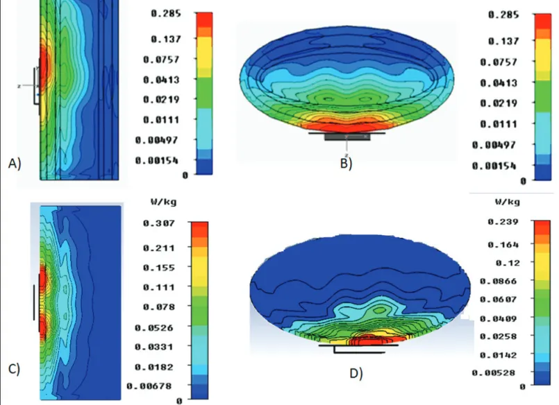
In order to discuss the compliance of the wearable sys-tem with exposure limits, some issues concerning the Specifi c Absorption Rate (SAR) and the radiated electromagnetic fi eld are discussed here for the on-body and the off-body setups with the help of numerical electromagnetic simulations. In the fi rst case, the same FDTD torso model previously adopted for the design of the wearable antenna was applied to estimate the resulting SAR distribution at 870 MHz, averaged over 10 g of tissue. The reader’s PIFA antenna was placed on the middle of the external surface of the cylinder, and radiated a fi xed 0.5 W power, as in the on-body experiments. The diagrams in
Fig-ure 15 for both vertical and horizontal placements of the PIFA had to be compared with the considered SAR limit of 2 W/Kg [36]. As expected, the maximum SAR occurred underneath the antenna, in correspondence with the muscular tissue, but it was one order of magnitude smaller than the absorption limit. This means that the cohabitation of the reader’s PIFA with the body was safe, even for the case of the maximum emitted power allowed by European (3.2 W EIRP) and US (4.0 W EIRP) regulations.
Concerning off-body communication, the experimental reading distance was simply discussed with respect to the maximum limit, E0, imposed on the fi eld radiated by the reader. The study in [21] addressed this topic by introducing a forbidden region all around the reader, wherein the emitted fi eld strength exceeded the allowed limit, and hence no person should be present inside for more than a given time, specifi c to the local regulation. In particular, the simulations in [21] showed that even in the case where the reader radiated 3.2 W EIRP, the extension of the forbidden region was less than 50 cm for E ≤0 20V/m. Moreover, such a distance was practi cally further reduced for the case of duty cycles d <1. For instance, assuming a typical inventory communication between reader and tag with ten interrogations per second, the resulting forbidden distance would be halved with respect to the case of continuous interrogation. Therefore, the off-body link was fully compatible with local regulations for body-tag distances larger than a small fraction of a meter.
7. Conclusion
The experiments presented demonstrated that passive body-centric RFID links are feasible within a regular indoor room with the technology available today, and within safety regulations. Actually, the on-body link may be established using a query power of the order of just 10 dBm in case where the tag is placed over the torso and the reader’s antenna is on the waist. This power requirement is compatible with pico-Figure 12. The normalized backscattered power, pBS, from
Tags A and D, as collected by the on-body PIFA antenna placed as in Figure 10, when the subject was standing motionless.
Figure 13. The normalized backscatt ered power, pBS, from Tags A and D, when the person walked along a straight line within a corridor, initially with a velocity of 60 cm/s, and then at 120 cm/s. The pBS power looked to be able to follow the walking dynamics.
Figure 14. The normalized backscattered power, pBS, from Tag E when the subject’s arm was moving up and down at a frequency of 0.5 Hz.
Figure 15. The Specifi c Absorption Rate (SAR) [W/Kg] of the human torso model wearing the reader’s PIFA antenna for vertical polarization (Cases A and B) and horizontal polarization (Cases C and D).
readers, as well as with conventional hand-held radios, and even with smart phones. Moreover, the continuous improve-ment in microchip sensitivity will permit extending the read-ing distance or, conversely, reducread-ing the required powers. New pervasive applications may therefore be envisaged, where low-cost and even disposable wearable tags will inter act with multi-service radio devices.
The position of the tags over the body has to be carefully chosen in order to avoid shadowing and excessive absorption. A single tag is not enough to establish an omnidirectional off-body link. Two or three tags placed over the chest, the shoul-ders, or over the arms permit interacting with the moving body from any angle and with remarkable reproducibility.
Finally, the backscattered power level in on-body confi gu-rations undergoes fl uctuations with amplitudes of from ±1dB up to ±4dB, depending on the position and on the motion. This issue has to be carefully taken into account in sensing applications based on RSSI processing. Such fl uctua tions may result in being synchronized to the movement of the arm to which the antenna is attached, revealing that selective motion detection could be possible by using very low-cost technology.
8. Acknowledgments
This research was supported by the Italian Ministry of University under funded project PRIN2008 “RFID MULTI-TAG.” The authors would like to thank G. Contri, A. Giuliani, and M. Trecca for technical support of the measurements.
9. References
1. S. Jongwoo, T. Sanchez Lopez, and K. Daeyoung, “The EPC Sensor Network for RFID and WSN Integration Infra structure,” Fifth Annual IEEE International Conference on Pervasive Computing and Communications Workshops, March 2007. 2. L. Cheng-Ju, L. Li, C. Shi-Zong, W. Chi Chen, H. Chun-Huang, and C. Xin-Mei, “Mobile Healthcare Service System Using RFID,” IEEE International Conference Networking on Sensing and Control, 2, 2004, pp. 1014-1019.
3. R. S. Sangwan, R. G. Qiu, and D. Jessen, “Using RFID Tags for Tracking Patients, Charts and Medical Equipment Within
IEEE Antennas and Propagation Magazine, Vol. 54, No. 4, August 2012 59
6. Safety Issues
In order to discuss the compliance of the wearable sys-tem with exposure limits, some issues concerning the Specifi c Absorption Rate (SAR) and the radiated electromagnetic fi eld are discussed here for the on-body and the off-body setups with the help of numerical electromagnetic simulations. In the fi rst case, the same FDTD torso model previously adopted for the design of the wearable antenna was applied to estimate the resulting SAR distribution at 870 MHz, averaged over 10 g of tissue. The reader’s PIFA antenna was placed on the middle of the external surface of the cylinder, and radiated a fi xed 0.5 W power, as in the on-body experiments. The diagrams in
Fig-ure 15 for both vertical and horizontal placements of the PIFA had to be compared with the considered SAR limit of 2 W/Kg [36]. As expected, the maximum SAR occurred underneath the antenna, in correspondence with the muscular tissue, but it was one order of magnitude smaller than the absorption limit. This means that the cohabitation of the reader’s PIFA with the body was safe, even for the case of the maximum emitted power allowed by European (3.2 W EIRP) and US (4.0 W EIRP) regulations.
Concerning off-body communication, the experimental reading distance was simply discussed with respect to the maximum limit, E0, imposed on the fi eld radiated by the reader. The study in [21] addressed this topic by introducing a forbidden region all around the reader, wherein the emitted fi eld strength exceeded the allowed limit, and hence no person should be present inside for more than a given time, specifi c to the local regulation. In particular, the simulations in [21] showed that even in the case where the reader radiated 3.2 W EIRP, the extension of the forbidden region was less than 50 cm for E ≤0 20V/m. Moreover, such a distance was practi cally further reduced for the case of duty cycles d <1. For instance, assuming a typical inventory communication between reader and tag with ten interrogations per second, the resulting forbidden distance would be halved with respect to the case of continuous interrogation. Therefore, the off-body link was fully compatible with local regulations for body-tag distances larger than a small fraction of a meter.
7. Conclusion
The experiments presented demonstrated that passive body-centric RFID links are feasible within a regular indoor room with the technology available today, and within safety regulations. Actually, the on-body link may be established using a query power of the order of just 10 dBm in case where the tag is placed over the torso and the reader’s antenna is on the waist. This power requirement is compatible with pico-Figure 12. The normalized backscattered power, pBS, from
Tags A and D, as collected by the on-body PIFA antenna placed as in Figure 10, when the subject was standing motionless.
Figure 13. The normalized backscatt ered power, pBS, from Tags A and D, when the person walked along a straight line within a corridor, initially with a velocity of 60 cm/s, and then at 120 cm/s. The pBS power looked to be able to follow the walking dynamics.
Figure 14. The normalized backscattered power, pBS, from Tag E when the subject’s arm was moving up and down at a frequency of 0.5 Hz.
Figure 15. The Specifi c Absorption Rate (SAR) [W/Kg] of the human torso model wearing the reader’s PIFA antenna for vertical polarization (Cases A and B) and horizontal polarization (Cases C and D).
readers, as well as with conventional hand-held radios, and even with smart phones. Moreover, the continuous improve-ment in microchip sensitivity will permit extending the read-ing distance or, conversely, reducread-ing the required powers. New pervasive applications may therefore be envisaged, where low-cost and even disposable wearable tags will inter act with multi-service radio devices.
The position of the tags over the body has to be carefully chosen in order to avoid shadowing and excessive absorption. A single tag is not enough to establish an omnidirectional off-body link. Two or three tags placed over the chest, the shoul-ders, or over the arms permit interacting with the moving body from any angle and with remarkable reproducibility.
Finally, the backscattered power level in on-body confi gu-rations undergoes fl uctuations with amplitudes of from ±1dB up to ±4dB, depending on the position and on the motion. This issue has to be carefully taken into account in sensing applications based on RSSI processing. Such fl uctua tions may result in being synchronized to the movement of the arm to which the antenna is attached, revealing that selective motion detection could be possible by using very low-cost technology.
8. Acknowledgments
This research was supported by the Italian Ministry of University under funded project PRIN2008 “RFID MULTI-TAG.” The authors would like to thank G. Contri, A. Giuliani, and M. Trecca for technical support of the measurements.
9. References
1. S. Jongwoo, T. Sanchez Lopez, and K. Daeyoung, “The EPC Sensor Network for RFID and WSN Integration Infra structure,” Fifth Annual IEEE International Conference on Pervasive Computing and Communications Workshops, March 2007. 2. L. Cheng-Ju, L. Li, C. Shi-Zong, W. Chi Chen, H. Chun-Huang, and C. Xin-Mei, “Mobile Healthcare Service System Using RFID,” IEEE International Conference Networking on Sensing and Control, 2, 2004, pp. 1014-1019.
3. R. S. Sangwan, R. G. Qiu, and D. Jessen, “Using RFID Tags for Tracking Patients, Charts and Medical Equipment Within