Alma Mater Studiorum – Università di Bologna
SCUOLA DI SCIENZE
Dipartimento di Chimica Industriale “Toso Montanari”
Corso di Laurea Magistrale in
Chimica Industriale
Classe LM-71 - Scienze e Tecnologie della Chimica Industriale
Tesi di laurea sperimentale
DEVELOPMENT AND IMPLEMENTATION OF AN
ALTERNATIVE METHOD FOR THE DETERMINATION OF
THE FIBER VOLUME CONTENT OF CFRP LAMINATES
CANDIDATO: RELATORE:
Emanuele Mainenti Prof. Tiziana Benelli
CORRELATORE:
Prof. Luciano Avila Gray
TABLE OF CONTENTS
CHAPTER 1 – INTRODUCTION
1.1 Composite materials Pag. 1
1.2 Matrix Pag. 2
1.3 Epoxy resins Pag. 4
1.3.1 HexFlow® RTM6 Pag. 6
1.4 Reinforcement Pag. 7
1.5 Carbon fiber Pag. 10
1.6 Interface Pag. 14
1.7 Composite manufacturing processes Pag. 15
1.8 Properties of CFRPs Pag. 20
1.8.1 Fiber Volume Content (FVC) Pag. 20
1.9 Methods for the determination of the FVC Pag. 22 1.10 Mechanisms of thermal degradation of polymers Pag. 23
1.11 Thermal degradation of CFRP Pag. 25
CHAPTER 2 – AIM OF THE THESIS
Pag. 28CHAPTER 3 – RESULTS AND DISCUSSIONS
Pag. 323.1 Specimens preparation Pag. 32
3.2 Acid Dissolution Method Pag. 33
3.2.2 Neat fibers and neat resins experiments Pag. 37
3.3 Burn-off Method Pag. 39
3.3.1 Neat fibers experiments Pag. 39
3.3.2 Neat resin experiments Pag. 42
3.3.3 Corrective factors Pag. 44
3.3.4 Fixed fibers weight experiments Pag. 45
3.3.5 Composite experiments Pag. 47
3.4 Improved Thickness Method Pag. 50
3.5 Comparison of the error propagations Pag. 56
CHAPTER 4 – CONCLUSIONS
Pag. 60CHAPTER 5 – EXPERIMENTAL SECTION
Pag. 625.1 Material and reagents Pag. 62
5.2 Instruments Pag. 63
5.3 Methods Pag. 64
Abstract
The fiber volume content (FVC) is a parameter that determines the mechanical, thermal and electrical properties of composite materials; it is therefore very important to be able to determine it accurately. Two methods (burn–off method and improved thickness method) for the determination of fiber volume content within composite materials were developed and implemented with the aim of providing an alternative to the current acid dissolution method that is laborious, dangerous and polluting. The three different methods were carried out on a carbon fiber reinforced polymer (CFRP) braided laminate and the results obtained by acid dissolution were used as reference values for the two implemented methods. Regarding the burn-off method, it was highlighted the importance of making corrections to the final measurements by two correction factors (R and L) that have been determined in this study. The improved thickness method results allowed concluding that this technique, in the presence of flat specimens, can be used as a quick and non-destructive method to have a first idea of the parameter.
Finally, the errors propagation on the measurements was determined, in order to compare the relative % error of the three methods.
1
1. INTRODUCTION
1.1 Composite materials
Composite material is defined as the union of two or more materials, which have, in combination, properties superior to those possessed individually [1].
It is generally constituted by a continuous phase, the matrix, inside which there is a dispersed phase, which represents instead the reinforcement. In addition to these two phases, organic or inorganic fillers are often used with the aim to reduce costs [2], enable the use of less matrix or change some of the properties of the final composite. Between the matrix and the reinforcement is finally present an interface that determines the correct adhesion between the two components and allows an effective stress transfer from the matrix to the reinforcement.
Unlike the metal alloys, the phases are quite distinct and each component retains its mechanical, chemical and physical properties.
In view of the above, it is easy to imagine how countless examples of composite materials are present in nature, starting from wood (composed of cellulose fibers held together by the lignin) up to bones (composed of hydroxyapatite and collagen) that exist and have been used since ancient times. Only starting from the thirties however, a genuine development on an industrial scale of composite materials began, with the discovery, in 1935, by Owens Corning of glass fiber and the subsequent marketing of reinforced polymers with this type of fiber [3].
During the Second World War, encouraged by military purposes, several research projects were launched with the aim of identifying new materials or production techniques that would further improve the properties of the composites, using, especially in aviation, the incredible lightness combined with high mechanical and chemical properties of these materials.
Unbound from the military context, in the following decades, new uses have been identified, which have allowed rapid development also in the automotive, naval, aerospace and most recently sports and medical sectors.
The versatility of composites is certainly due to the considerable amount of matrices and reinforcements that can currently be combined in order to give the material the desired properties.
2
1.2 Matrix
The matrix constitutes the continuous phase of the composite material and has the purpose of maintaining the orientation and the spacing between the fibers, protecting them from external agents and from abrasion, as well as allowing a stress transfer on the reinforcing fibers and giving shape to the final product. It has a very important role because it determines the maximum service temperature of the composite, the moisture sensitivity and the aging resistance [4].
There are several types of matrix and their choice is made on the basis of the applied reinforcement, the manufacturing process and the required properties.
You can have three different matrices:
o Metallic: made up of metal monocrystals. Light metals such as aluminum, magnesium or titanium, are typically used. This type of composite materials is mainly used when you want temperature and abrasion resistance; they also have the great advantage of being able to be used as alloys, in order to improve the mechanical and chemical properties of the same, according to your needs. Unlike other matrices, the incorporation of reinforcements does not change much the mechanical properties of the composite, but instead has the purpose of improving the wear resistance, creep and thermal distortion [5]. However, these metals are very reactive and have a high affinity with oxygen. This leads to complications during production and makes it necessary to use an external coating in the reinforcements to prevent them from reacting with the continuous phase.
The main use is currently in the automotive field, to lighten the metallic components [6]
o Ceramic: consisting of ceramic materials such as Alumina (Al2O3), Silicon Carbide (SiC), Mullite (Al2O3 + SiO2) or Zirconia (ZiO2). Their development has been linked to the need to overcome some known issues of classical ceramics, which, despite having very high resistance to high temperatures and chemical inertia, tend to fracture without excessive difficulties due to mechanical loads, both under normal conditions and at high temperatures. This is due to the presence of defects in their structure, which act as a starting point for the propagation of cracks [7]. The inclusion of fibers, particles or lamellae inside the matrix thus acts as an
3
obstacle to the propagation of the cracks, greatly improving the fracture toughness. Moreover, these composites also have very high resistance to thermal shock and a lower weight than conventional ceramics.
At present, they are widely used as thermal protection systems in the aerospace industry or brake components [8].
o Polymeric: consisting of polymeric materials. Composites made up of these matrices have had the greater development in recent years as they have unique properties of high mechanical properties, combined with low weight and good corrosion and abrasion resistance
There are two types of matrices:
o Thermoset: a resin subjected to an irreversible curing stage, in which it passes from a viscous liquid to solid. The curing process is induced by the action of heat or by a radiation, usually in the presence of high pressures. It consists of the formation of an insoluble and infusible tri-dimensional (cross-linked) network, in which covalent bonds are formed between the different chains of the resin. The solid thus obtained can no longer be melted and has good resistance to temperature, high mechanical properties and hardness but high fragility (9).
The most used resins are epoxy, polyester, vinyl ester and phenolic resin.
o Thermoplastic: Unlike thermosetting resins, thermoplastic polymers do not have cross-linking between the various chains but they are only physically intertwined (entanglements). This results in lower mechanical and thermal properties, however balanced by the possibility of fusing and re-working them and by higher values of % elongation. They exhibit a higher processing temperature of the resins, as they have very high molecular weights that result in higher Tg. An important advantage is to have significantly lower costs than thermosetting resins.
The most used thermoplastic polymers are Polyether ether ketone (PEEK), Polypropylene, Nylon 6.6 and Polyphenylene sulfide (PPS).
4
1.3 Epoxy resins
Despite the extensive development in thermoplastic matrices in recent years, in the high performance composite field, a predominant role is still occupied by epoxy resins. There are several factors that have led to their extensive use, first among all their versatility. In fact, it is possible to obtain epoxy resins by combining different types of reagents, as well as different curing cycles, which lead to different properties. High mechanical and thermal resistance can be obtained, as well as high elasticity or abrasion resistance, resulting in the use of these resins in the most varied fields, from adhesives to aerospace fields (10). There are no secondary volatile products during treatment, and there is no shrinkage, typical of unsaturated polyester resins, which would lead to an increase of the internal stress. They also have a low molecular weight before being cured, which allows exceptional mobility of the molecules undergoing treatment, making fiber impregnation easier (11). The main problems are related to high costs and long production times due to rather slow cross-linking. An epoxy resin can be defined by two main elements:
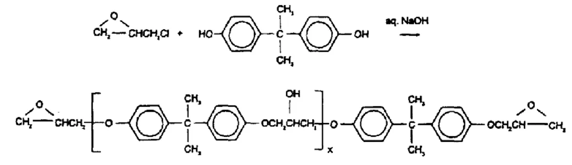
o Basic Component: molecule in which at least two epoxy groups are bonded to a molecular chain, which can vary within a wide range, depending on the length or the groups present, whose composition has a large influence on the final properties of the resin. Figures 1 and 2 show the most commonly used base components. The first one is diglycidyl ether of bisphenol A, obtained from the reaction of Bisphenol A with epichlorhydrin. It can be seen as a pre-polymer, whose molecular weight can be controlled by the stoichiometric excess of epichlorhydrin, which makes it liquid/viscous or solid [12].
The aromatic rings of the bisphenol A provide good thermal properties and mechanical strength even at high temperatures, while the hydroxyl and aliphatic groups in the chain provide respectively adhesive properties and flexibility.
5
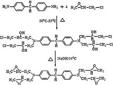
The second component (Figure 2) is tetraglycidyl 4,4'-diaminodiphenylmethane, obtained from the reaction of 4,4'-diaminodiphenylmethane with epichlorhydrin. In this case, a tetrafunctional pre-polymer is obtained which allows to obtain a greater cross-linking and higher mechanical strength and temperature resistance.
Figure 2. Tetraglycidyl 4,4'-diaminodiphenylmethane
o Crosslinking Agent: By reacting pre-polymers with curing agents or hardeners, tri-dimensional, infusible and insoluble networks are obtained. The crosslinking agents can be of two types: catalysts or hardeners. A catalyst acts as an initiator of homopolymerization of the epoxy resin or as an accelerator in the presence of another curing agent (crosslinker), while the curing agent acts as a comonomer in the crosslinking process [13]. The crosslinking agents acting as catalysts are a group of compounds that promote both the ring opening reactions of the epoxy groups and the crosslinking reaction. Most epoxies are crosslinked through a ring opening mechanism with an anionic initiator, which occurs in the presence of a nucleophile. Hardeners for epoxy resins are compounds with active hydrogen atoms such as primary and secondary amines, phenols, thiols and carboxylic acids [14]. Aliphatic amines are used for curing cycles at room temperature, while aromatic ones are less reactive and require high temperatures or accelerators. The two most used curing agents are shown in Figure 3. It is possible to observe that in both cases secondary amines are present, with two active hydrogen atoms, which
6
can react with two epoxide groups. Primary amines react faster than secondary ones. The reaction of the epoxide group with a primary amine initially produces secondary alcohol and a secondary amine, which in turn is able to react with another epoxy group to give a tertiary amine and two secondary hydroxyl groups.
Figure 3. 4,4’-Methylenedianiline MDA (a), 4,4’-Diaminodiphenylsulfone DDS (b)
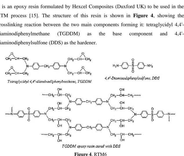
1.3.1 HexFlow® RTM6
It is an epoxy resin formulated by Hexcel Composites (Duxford UK) to be used in the RTM process [15]. The structure of this resin is shown in Figure 4, showing the crosslinking reaction between the two main components forming it: tetraglycidyl 4,4'-diaminodiphenylmethane (TGDDM) as the base component and 4,4'-diaminodiphenylsulfone (DDS) as the hardener.
7
The resin is supplied as monocomponent, in which the basic component and the curing agent are already mixed. According to the datasheet of the resin, several curing cycles are possible, leading to different properties of the final resin, as shown in Table 1.
Table 1. Curing cycles and expected properties.
Cycle 1 Cycle 1 + Post curing
Cycle 2 Cycle 3 Cycle 4 Cycle 5
Curing Cycle 160°C 180°C min. min. 75 / 75 120 120 / / 60 / 90 / 120 Tg °C 160 183 173 189 193 196
This resin, in addition to the known high mechanical properties of classic epoxy resins (Young’s modulus of 2890 MPa) combined with low density (1.14 g/cm3) [16], also exhibits higher resistance to high temperatures, as well as a low tendency to absorb water and a relative ease of processing. The major drawback is the fragility, due to the high number of cross-links present between the various chains.
They therefore find vast use in the aerospace field and for high performance applications.
1.4 Reinforcement
The reinforcement represents the internal fraction and discontinuous phase of the composite. It has the main purpose to receive and unload the stress from the matrix and to prevent the formation or propagation of cracks in the matrix. It therefore gives the composite high mechanical properties and hardness.
The reinforcement may be fibrous or particulate. In the particulate composites, the reinforcement consists of "particles" (sand, alumina, titanium carbide or the like) which can be assumed equiaxial, that is, the ratio between diameter and length of each particle is approximately equal to one [17]. This gives the material isotropic properties, equals in all directions.
They usually do not constitute more than 40% of the total volume due to the excessive fragility that they give to the product.
In this case, the final properties of the composite depend on the size and shape of the particles and their concentration and distribution within the matrix [17]. Their use is mainly
8
due to the high hardness and wear resistance that they give to the final product, combined with ease of processing and their relatively low cost.
They are mainly used for road surfaces or where high mechanical properties are not required.
In fibrous composites, however, reinforcement consists of fibers, usually glass, Aramide or carbon. The fibers are small monocrystalline filaments with a diameter of about 10μm, which have a very high length/dimeter ratio (aspect ratio), which gives it high mechanical properties that increase with a decrease of transversal dimensions [18]. This type of reinforcement increases the tensile strength, while maintaining a relatively low weight. It has therefore been widely used in sports, automotive and aviation.
Depending on the size and distribution of fibers within the product, there can be
discontinuous or continuous reinforcements. In the first case, short fibers are used, with
a maximum length of some cm, randomly dispersed within the matrix (Figure 5C). They lead to an almost isotropic reinforcement, and at present they find non-structural uses, where is given more importance to the weight of the product rather than performance. In continuous reinforcements, however, are used long fibers with a length of more than 10cm, arranged in an orderly and oriented manner. They may have unidirectional or bi-directional arrangements. In the first case, at least 90% of the fibers are oriented in the same direction [19] (Figure 5A); the fibers are held together by stitching in organic material, they are light and lead to a composite characterized by a high tensile strength along the axis of the fibers, while exhibiting a weaker reinforcement in the perpendicular direction [20]. The bi-directional fibers (Figure 5B) are woven into weft and warp (with angles of 0° and 90°) and this allows to have good properties, even if lower than the unidirectional reinforcement, along the orientation of the fibers [20].
With the improvement of manufacturing and weaving techniques, it has been possible to implement even more complex "fabric" geometries (Figure 5D) where fibers are interwoven according to the desired geometry to obtain the desired properties.
9
Figure 5. Fibers architectures [21]
The most used geometries are essentially three [21]:
o Plain Weave (or Canvas): It is the easiest way to weave warp and weft (Figure
6A). Each of them passes alternately over and under the other, at each step. It has
the maximum number of binding points, which make the fabric very tough but not flexible; there are also the same properties in both faces of the fabric.
o Twill Weave (or Saw): In this case, each weft passes alternately over and under two or more warps and vice versa (Figure 6B). This results in a pattern of diagonal lines characteristic of this fabric. The less fiber waviness determines the better mechanical properties and unlike the plain weave, they have greater flexibility even if they have higher costs.
o Satin: it is fundamentally twill weave modified to produce fewer intersections of warp and weft (Figure 6C). It is often defined by a number that indicates the number of fibers above and below which the weft passes before repeating itself again. The low number of overlays makes these fabrics very flat and more wettable. Low waviness also provides high mechanical properties. The main defects are caused by the low stability of the structure and the asymmetry along the two faces, which causes a fabric face to have a higher number of fibers in the warp direction and the opposite in the other face. It is therefore necessary to pay particular attention if you want to stack multiple layers for a laminate to ensure that this does not affect mechanical properties.
10
Figure 6. Fabric geometries [21]
In relatively recent times, laminates have been developed: they consist of different sheets of continuous fibers, generally unidirectional or fabric, stacked according to different orientations, allowing to obtain high properties along different directions [22]. The assembly of the laminates is made by polymerization or using adhesives. They are widely used in the automotive and aerospace industries.
1.5 Carbon Fiber
Among the fibrous reinforcements, carbon fibers are those which have been more widely used in areas where high performances connected to lightness of the final product, are required.
With the term carbon fiber, we often refer improperly to the composite where the fiber is, instead, the reinforcement. Carbon fiber can be seen as a mono-dimensional filament, consisting almost exclusively of carbon atoms (> 92%) [23], with a length / diameter ratio greater than 100 [24]. As shown in Figure 7, within the filaments, carbon atoms, with sp2 hybridization, are arranged in hexagonal geometry to form sheets (graphene), which constitute the different planes of the structure. The strength of the covalent bonds between the carbon atoms results in high resistance along the a-direction [25], which corresponds to the fiber axis.
11
Figure 7. Graphite structure of carbon fibers [25]
Atoms are arranged in a graphite or non-graphite structure (turbostratic) as shown in
Figure 8.
Figure 8. Carbon fibers arranged in a turbostratic structure [28]
The fibers with turbostratic structure have a two-dimensional long-range order along the planar hexagonal plane of the single plane (a-direction in Figure 7), whereas they do not have a crystalline order along the third dimension (c-direction) [25]. The latter has a long-range amorphous structure, with the different planes bending and mechanically linking to each other, thus increasing the fiber resistance along the c-direction and showing a higher tensile strength.
The graphitic structure, on the other hand, has a long-range crystalline order, along all three dimensions, which grants to the fibers a high Young's modulus and thermal conductivity. The main characteristics of carbon fibers are the low density (1.7-2.2 g/cm3) [26] combined with high mechanical properties such as tensile strength (1.3-7.7 GPa) [27] and the elastic modulus (230-935 GPa) [27]; they also have a very low thermal expansion coefficient and a high fatigue strength [28]. The fibers can be classified according to the mechanical characteristics and the production method used.
12
Method 1: Modification of organic fibers (polyacrylonitrile, PAN) as precursors, is used in the production of about 90% of fibers in the world [29]. The process is divided into three phases: heating/oxidation, carbonization and graphitization. The most important process is the heating/oxidation, where the cross-linking of PAN chains is favored and in general, it makes the structure more stable in order to withstand subsequent steps, preventing fiber fusion or volatilization of the atoms of carbon. It is carried out at about 300 ° C and in the presence of oxygen. The chemistry of the stabilization process consists in the transformation of the triple bond of the nitrile group into a double one and in the formation of a new bond between the nitrogen of a nitrile group and the adjacent carbon (Figure 9). There is therefore a cyclization process with the formation of aromatic rings.
Figure 9. PAN aromatization reaction mechanism proposed by Houtz [30]
After being stabilized, the precursors undergo a carbonization process, which modifies both the physical properties and the chemical composition of the material, leading to the formation of carbon fibers. The process, described in Figure 10, is carried out at 700-1300°C in an inert environment (N2 or Ar) and eliminates all elements outside of the carbon, as gas. It is divided into two stages: a pre-carbonization at about 700°C, to avoid an excessive thermal shock of the fibers, where the aromatic chains formed previously, merge laterally through the expulsion of hydrogen atoms, released in the form of gas. The result of this process is the formation of "tape" polymers. Subsequently, increasing the temperature up to about 1300°C, the nitrogen atoms are gradually expelled in gaseous form as a result of the progressive lateral fusion of the “tape” polymers and wider tape are formed, with the planes arranged in a turbostratic structure.
13
Figure 10. Carbonization processes at 700 and 1300°C [31]
In order to obtain fibers with a high Young’s modulus, at the disadvantage of the tensile strength [30], there is a final process, called graphitization. In this stage, the previously obtained turbostratic structure is transformed into a graphite structure with a longrange order on all three dimensions, by thermal treatment at 2500 -3000°C in Ar atmosphere.
Method 2: Use of precursors obtained from petroleum or tar distillation residues (pitch) consisting of a mixture of aromatic hydrocarbons. They are thermally treated at 450°C, with the formation of a mesophase. By extrusion through a capillary, the mesophase molecules are oriented along the fiber axis and finally by carbonization (2000°C) in an inert atmosphere, all non-carbon elements are eliminated [32]. The final structure obtained by this method is graphitic.
Regarding the classification by mechanical properties, there are three major categories [33]:
High tensile strength fibers: they are obtained with the PAN method and have turbostratic structure. They have a tensile strength of 4-6 GPa and elastic modulus below 100Gpa.
Intermediate Fibers: They have an elastic modulus between 200-350 GPa. High elastic modulus fibers: usually obtained with the Pitch method, they have
graphitic structure. They have an elastic modulus higher than 450Gpa and a tensile strength around 2.5 GPa.
The first use of carbon fibers dates back to 1879 when T. Edison used carbon fiber filaments obtained by baking at high temperatures and in controlled atmosphere, some chopped bamboo fragments in the first incandescent bulbs [34]. With time however,
14
carbon fiber filaments were replaced by the more resistant tungsten filaments, and consequently the carbon fibers disappeared from the industrial landscape. It was only in 1956 that Union Carbide started to develop high performance fibers at the “Parma Technical Center”, Ohio; it was here that physicist Roger Bacon, during an experiment to determine the triple point of the graphite using an electric arc furnace, noticed that on the negative electrode were condensed, from the vapor phase, some thin filaments (whiskers) [35]. They were constituted by graphite sheets perfectly perpendicular to the cylindrical axis, which acted as if they were single crystals along the filament axis and exhibited surprising mechanical characteristics. In the following years, new fiber production techniques were developed, studying the use of new precursors, until A. Shindo, a Japanese researcher, in 1961 succeeded in synthesizing high-modulus fibers, using polyacrylonitrile (PAN) as the precursor, a polymer obtained by polymerization of acrylonitrile [35]. This, as already discussed above, is still today the most used method.
1.6 Interface
It has an important role on the overall physical and mechanical properties of the composite. It is essential to have a good adhesion and wettability between matrix and reinforcement in order to have a good synergy between them. A low cohesion between matrix and reinforcement results in an incorrect distribution of the applied load, which would only weigh on the weakest part of the composite that is the matrix.
At molecular level, the interaction of the two phases is determined by the chemical structure of both phases and is due to Van der Waals forces, acid-base interactions or chemical bonds. [25]
The fibers have low wettability and adsorption in the resin, for this reason the adhesion is often promoted by the use of a third organic or inorganic component called sizing, applied in a very thin layer on the surface of the reinforcement. Surface treatments such as acid oxidation or plasma treatment, are also often used to increase the surface area of the fibers or the number of reactive groups that can facilitate the adhesion with the matrix [26].
15
1.7 Composite Manufacturing Processes
Vacuum Bag Moulding
It is the most used technique to obtain composites that can be used in the aerospace field and in applications where are required artefacts, even of large dimensions, with high mechanical properties and excellent surface finish [36]. In this process, (Figure 11) the final product is obtained by a lamination process, in which a fixed number of layers of woven fiber impregnated in a partially cured resin (pre-preg) is manually overlapped inside a mould. The latter, which has the shape of the piece to be obtained, is then placed in a vacuum bag in order to remove any air bubbles that would adversely affect the final properties of the composite and to compact the layers of fiber. The final step consists in placing the laminate inside an autoclave under controlled pressure and temperature, to complete the curing cycle and to obtain the final piece.
Figure 11. Vacuum Bag Moulding [36]
Hand Lay-Up
It is the simplest method and allows to obtain artefacts with complex shapes [37]. Firstly, a coat of gel is applied in the open mould, as a coating; the reinforcing fibers (in the most common case, glass fibers), usually in the form of fabrics, are placed manually in the mould, then the resin is applied and homogeneously distributed with metal or plastic rollers, which also have purpose to remove trapped air. The process ends with the final curing at atmospheric pressure.
16
Spray Lay-Up process
A popular variant for manual lamination is the spray lay-up technique, shown in Figure
12. It is widely used in nautical applications and consists in spraying simultaneously resin
and short fibers, with a suitable vaporizer-cutting gun [38]. The compressed air sprays the mixture on the rotating mould, in order to uniform the deposition. This technique is used for forming of pre-forms, that is semi-finished parts of the final piece, which are then placed between the two parts of the mould and the final piece is formed by hot-melted die moulding.
Figure 12. Spray Lay-Up [38]
Filament winding
The filament winding technique is well suited for the production of axial parts such as tanks, tubes and fishing rods, or non-circular cross-section such as wing profiles for helicopter blades [39]. The manufacturing is performed by winding machines, in which a spindle of the right shape rotates, moved by an electric motor, as shown in Figure 13. At the same time, one or more tapes are unrolled from rotating coils and, by means of a movable carriage, are wound around the spindle. During the winding or in a subsequent phase, polymerization is performed. It is possible to vary the mechanical characteristics, changing the winding angle: for example, a narrow winding angle enhances the resistance to radial stresses, a high angle favours the resistance in axial direction [40].
17
Figure 13. Filament Winding [40]
Pultrusion
The extreme automation is one of the great advantages of this process that allows to make a large number of pieces at very high speeds. It is well suited for the production of semi-finished profiles with a constant section with mainly monodirectional fibers such as pipes, tubes and beams [41]. In the pultrusion process, the continuous fibers are impregnated in a resin bath, passed through a heated and drawn mould, slowly exiting as a crosslinked composite material with a constant cross-section, as shown in Figure 14.
18
Prepregs
This process is the most used to produce flat laminates, or with certain curvatures, using an autoclave. The laminate is prepared with a cold process, overlapping the various pre-impregnated layers. Then it is placed in an autoclave or in heat presses, in order to polymerize it under pressure at temperatures of about 180°C. This technology is expensive, but allows to obtain high quality mechanical components with good manufacturing quality, minimizing manufacturing defects [42].
Resin Transfer Molding (RTM)
In the Resin Transfer Moulding (RTM) process, the reinforcement (pre-formed fiber fabrics) is placed inside a mould; the latter is then closed and vacuum is applied. Subsequently, pressurized injection (1-5 bar) of the resin mixed with the curing agent is carried out inside the mould [43]. The polymerization is carried out at room temperature or under heat, with or without catalyst. This technology allows to obtain high fiber/resin ratios with low voids content; the pieces have a high surface finish due to the pressure exerted by the two mould elements. This process is also easily automatable, reducing labour costs and making it more scalable [43].
Braiding
Braiding is a weaving process known for its simplicity and versatility. The peculiarities of the products produced with this technique are conformability (surfaces with double curvature), torsional stability and damage tolerance [44]. In the braiding process, the fibers are present in the form of yarns, consisting of thousands filaments of parallel fibers, twisted together; According to the thousands of filaments present, there are 1K, 3K, 6K, 12K, 24K yarns, which obviously have different costs and properties [45].
Two or more yarn systems are then twisted to create an integrated structure with the desired texture, thus obtaining a variety of shapes, orientations and fiber volume fractions. Although braiding cannot match filament winding in terms of fiber content, it can produce more complex shapes and anti-clastic curvatures [46]. Moreover, the braided artefacts possess intrinsically high structural integrity, tolerance to damage, intra- and inter-laminar tenacity and compared to filament winding, braiding also allows to obtain longitudinal orientation with respect to the spindle axis.
19
Studies carried out by the McDonnell Douglas Corporation have shown that braiding composites can be produced at 56% of the cost of the same realized by filament winding due to the reduction of labour force in the assembly and to the simplification of the design [47].
The most attractive feature of braiding is simplicity: a typical machine (Figure 15) consists of:
1) a plate containing the tracks 2) the spool carrier
3-4) a twist trainer 5-6) a collection system.
Figure 15. Braiding [44]
The weave is defined by the braiding angle θ, that is, the angle formed between the direction of the fibers and the axis of the machine. The compactness of the braid is related to the frequency with which yarns are interlaced. The distance between the overlapping points is called pick spacing; the plate with tracks receives the supports of the spools, which move along the tracks themselves. The supports are moved by a gear system; the supports, in addition to wearing the spools of yarn, also regulate the tension of the latter. At the interweaving point, a special trainer controls the shape and size. The finished article is gradually wound around a coil at a predetermined speed. The twisted components are made with RTM technology. This technology, with carbon fiber twists, derives from the textile industry and is used for the manufacture of tubular components for special applications,
20
such as structural uprights but also for helicopters, in components like beams, sandwich structures, frames, and panels. Similarly, they are used to manufacture complex beam structures and floor panels in passenger cars.
The properties of the final product depend strongly on the braiding angles and geometries used, but generally, high-impact resistant pieces are obtained, due to an efficient distribution on the applied load [48]. In addition, better interlaminar adhesion is obtained between the different layers, and by varying the shape of the coil, more complex geometries can also be obtained.
1.8 Properties of CFRPs
Carbon Fiber Reinforced Polymers (CFRP) are composite materials in which a polymer matrix and a carbon fiber reinforcement are present. As said before, the main properties of these materials are high chemical resistance and mechanical strength, high rigidity and toughness, low density and therefore low weight [49]. Further advantages include excellent fatigue strength and high wear and corrosion resistance associated with low thermal expansion coefficients [11]. All of these properties depend on several factors: the degree of graphitization of the fibers, the type of matrix and their density, the number of filaments of the yarn or the fibers orientation in the composite [50]. One of the most important parameters that must be taken into account is however the fiber volume content.
1.8.1 Fiber Volume Content (FVC)
It is often designated with acronym FVC and it is defined as the ratio between the volume of the fibers in the composite and its total volume [51]. It is a very important parameter, that should be defined during the manufacturing phase, which strongly influences the hardness, mechanical strength and thermal conductivity of the material. A rule of mixture approach [52] allows us to define the overall elasticity module such as:
Etot = EfVf + EmVm
where: Ef is the fibre modulus of elasticity, Em is the matrix modulus of elasticity, Vf is the fibre volume ratio, Vm is the matrix volume ratio.
21
As can be seen, the overall elastic modulus is closely related to the fiber volume content in the composite.
The theoretical maximum value of FVC is determined by the way fibers are arranged inside the composite. If they have a hexagonal array packing (or close-packed array), considering all the fibers in contact with each other, as showed in Figure 16b, the maximum fraction of fibers is:
𝜋
2 √3= 0,91
For a square array packing (Figure 16a) is: 𝜋
4 = 0,79 [53]
Figure 16. Fibers packing arrangements
Prior to these physical limitations, however, there are limitations related to the difficulty in the manufacturing of composites with high FVC values, as well as the importance of a good resin/fiber balance to allow effective impregnation of all fibers in order to keep them cohesive and separated, to have a good stress transfer on the reinforcement. Given all of that, the maximum limit for the fiber volume content is between 0.65 and 0.7 which can be obtained in prepregs or by filament winding [54].
Related to the FVC value, there is the matrix volume content (MVC) which refers to the content of matrix in the composite. The importance of the latter is mainly related to the fact that by knowing these two values, it is possible to calculate the void volume content (VVC) that is the porosity of the composite. This is a very important parameter, in particular in the aerospace industry, where there is usually a 2% limit of accepted porosity in order to use these materials [55]. In fact, the presence of pores constitutes a favorable point for the development and propagation of cracks and results in an incorrect adhesion between matrix and reinforcement. A decrease in longitudinal and transverse flexural
22
strength and modulus, longitudinal and transverse tensile strength and modulus, compressive strength and fatigue resistance has been observed [56].
There are different techniques for direct porosity measurement, such as X-ray Computed Tomography [57] or the Ultrasonic Attenuation [58] which are, however, currently very expensive and not really accurate.
Porosity usually develops during manufacturing and can be of two types: laminate, if formed between the different layers of a laminate or inside the resin, if incorporated into the laminate. To keep these values low, in the manufacturing processes is usually applied vacuum.
From this point of view, knowledge of these three parameters is crucial for both composite producers in order to ensure at the quality control stage that the desired relationships and the buyers have been respected in order to verify the veracity of the datasheet provided.
1.9 Methods for the determination of the FVC
Different methods of analysis are reported in the literature that have been used to measure the carbon fiber content in composites [59].
The most commonly used method, at present, is the so-called acid digestion. It consists in the removal of the matrix by a combination of chemical substances, which proceed to eliminate it selectively. For this purpose concentrated nitric acid or a combination of concentrated sulfuric acid and hydrogen peroxide at high temperatures can be used. The main advantage is given by the accuracy of this method, because it completely eliminate the resin, without damaging the fibers and by the fact that there is a standard for the carbon fibers to be referred to [59]. However, there are some disadvantages like the excessive duration of the method, due to the elaborate preparation of the specimens and conditioning of the residual fibers, as well as the use of hazardous and polluting substances at high temperatures.
Another possible method is the Optical Microscopy Analysis [54]. In this method slices of the specimens are analyzed by two-dimensional image processing to determine the fiber content. This may also lead to misrepresentation from studying three-dimensional features (fiber volume/weight content) using two-dimensional characterization (fiber area on a polished surface). To get enough accurate results, a large number of areas need to be analyzed. This approach is not practical as specimen preparation and image analysis are
23
extremely time-consuming and expensive. In addition, it can only be used when there is a unidirectional fiber distribution, while it is unusable for more complex geometries, as in the case of Braided Composites.
Thermogravimetric Analysis (TGA) could also be used to measure the carbon fiber content [60]. In this method, a sample weighing less than 0,1 grams is used. However, this small sample size is not sufficiently representative of carbon fiber composite structures. The TGA method has not been widely adopted because of the low confidence level derived from using small sample size (0.1 grams) to represent large composite structures. Both the microscopy and the TGA methods are limited in their accuracy and reliability.
Finally, another non-destructive method is the thickness method [59]. As it can be seen from the name, the first step consist in measuring the thickness of the specimen in ten different points, to have an average value. It is important for this reason that the specimens are flat and do not have surface roughness, which can alter this measurement. The obtained value is then used within a formula in which appears the areal weight, that can be known or measured, and the density of the fiber, in order to measure the FVC. The formula used is the following:
𝐅𝐕𝐂 =
𝐅𝐀𝐖 ∙ 𝐧°𝐩𝐥𝐢𝐞𝐬𝛒𝐟𝐢𝐛𝐞𝐫 ∙ 𝐭𝐡𝐢𝐜𝐤𝐧𝐞𝐬𝐬
where FAW is the fiber areal weight and n° plies is the number of plies that are present in the laminate. This is certainly the fastest and most cost-effective method, as it only requires measuring the thickness and the areal weight if not known. The main defect is that it can only be used for the measurement of the FVC and does not allow having information about the matrix volume content and porosity. Another drawback is the accuracy, as it is complex to obtain a laminate with a constant thickness throughout the profile and at the same time it is important to use a solid and precise method for measuring the areal weight, which has a major influence on the final result [61].
1.10 Mechanisms of thermal degradation of polymers
Depolymerization and statistical fragmentation of chains are generally the two mechanisms of degradation of polymers [62]. The rate and extent of degradation may be monitored by changes in a sample’s mass and molecular weight, detection and quantification of reaction enthalpy changes, quantitative analysis of reaction by-products
24
such as carbonyls. The factor that limits polymer thermal stability is the strength of the weakest bond in the polymer chain. Thermal degradation of polymers can follow three major pathways [62]:
o Side-group elimination: it takes place generally in two steps. The first step is the elimination of side groups attached to the backbone of the polymer. This leaves an unstable polymer macromolecule that undergoes further reactions, including the formation of aromatic molecules, scission into smaller fragments, or the creation of char [63].
o Random scission: it involves the formation of a free radical at some point on the polymer backbone, producing small repeating series of oligomers, usually differing in chain length by the number of carbons. Statistical fragmentation can be initiated by chemical, thermal or mechanical activation or by radiation. If such random scission events are repeated successively in a polymer and its degradation products, the result is initially a decrease in molecular weight and ultimately weight loss, as degraded products with a broad range of carbon numbers become small enough to evaporate without further cleavage.
o Depolymerization: it is a free-radical mechanism in that the polymer is degraded into the monomer or comonomers that make up the polymer. The formation of a free radical on the backbone of the polymer causes the polymer to undergo scission to form unsaturated small molecules and propagate to the free radical on the polymer backbone. The mechanism of depolymerization can occur under the same condition (high temperature) as statistical fragmentation.
In most of cases, the three degradation pathways happen at the same time in a degradation process. Different pathways dominate at different temperature ranges based on the structure of the polymers. At the end of the degradation process, the carbonization process is normally the dominating degradation behaviour, especially in inert atmospheres. In this process, the polymer chain transfer to a variety of products by forming the char at a high pyrolysis temperature [62]. The residue weight appeared to remain constant.
25
1.11 Thermal Degradation of CFRP
The degradation of carbon fiber composites, follows a path that depends on several factors, including the type of atmosphere in which occurs the degradation (in the presence of oxygen or not), the composition of the matrix, the presence of defects, the FVC, etc. In general, when there is an epoxy resin matrix, three different steps can be identified [64]:
o Matrix decomposition: this first step takes place at a temperature in the range 250-450°C [64]. Epoxy resin cracked in low molecular volatile species (endothermic reaction) with unzipping, stripping and cross-linking, which promote char formation (exothermic). This first step is independent of heating rate and oxygen concentration, because it occurs in both inert atmosphere and in the presence of oxygen. A diagram of what happens is shown in Figure 17. Resin decomposition occurs in the Pyrolysis zone. The resin condensation and cyclization lead to the formation of a char: a porous (traps volatiles from the Pyrolysis zone) layer that gives thermal insulation and oxidation-resistance to the below layer [65]. Higher aromatics presence in the composite leads to a higher percentage of char. There is a diffusive mass transfer of the volatile gas species from the internal areas of the composite to the gas zone (char acts like a barrier) and a diffusive oxygen mass transfer between the gas zone, the char zone and the pyrolysis zone [65]. Delamination can accelerate the composite degradation.
26
o Oxidation of the resin char: This step occurs at a temperature between 500 and 580°C. In this step, the char acts as a barrier to a further decomposition of the residual resin and fibers, inhibiting the flow of heat and oxygen from the gaseous zone to the condensed zone (Figure 17). In this case the oxygen concentration has a very important role.
o Oxidation of the carbon fibers: occurs at a temperature between 550 and 800°C. It is an exothermic process driven by the heat released by the reaction. The speed at which fibers oxidize depends on several factors such as the level of graphitization of the fibers, the presence of pores or defects, and especially the concentration of oxygen present [50]. Degradation occurs with CO and CO2 release.
28
2. AIM OF THE THESIS
Carbon fiber composites have had a rapid development over the last decades and they are still on the rise, so much so that the volume of market demand is likely to double within ten years [66]. The market share of composite materials that has been more successful is without a doubt the Carbon Fiber Reinforced Polymers (CFRPs), which represent a perfect combination of the extremely high mechanical strength and chemical inertia of carbon fibers with the lightness and machinability of polymers. Possible uses of these materials are extensive and widen daily. They are used in aircraft components and structures, where their superior strength to weight ratio exceeds that of any metal. It is estimated that 30% of all carbon fibers (CFs) is used in the aerospace and defense industry [67], from helicopters to gliders, fighter jets to microlights. They are widely used also in spacecraft components due to their thermal expansion coefficient close to zero. Over the last few years, there has also been a growth in the sports sector, where it is demanded a combination of lightness and design quality; in this sense, they were used in tennis rackets, bicycle frames and golf clubs.
Even though the industrial scale production started from the early 1970s, due to several challenges in their manufacturing, the production volume did not grow on par with the increasing demand; as a result, the price of CFs based materials remains still high.
At the moment, the two main drawbacks are the production costs of carbon fibers and their manufacturing. Currently, the used CF precursors are polyacrylonitrile (PAN) and pitch fibers; both of them originated by petroleum and as such they follow its price trends. For this reason, alternative precursors, such as lignin, are being sought, which allow lower costs, while retaining the final fiber properties.
As regards manufacturing, costs are related to the growing demand of materials with very high properties and complex geometries of the reinforcements. To this end, the main focus has been paid on the design of the parts, with the development of the techniques of lamination and braiding, by which certain properties can be obtained by varying the reinforcement arrangement in the matrix. In addition to the type of geometry used, the final properties of the composites are closely related to the fraction of fibers present within the product and its porosity. These parameters have a decisive influence on mechanical, thermal and electrical properties. Thus, it is of fundamental importance to define the value of Fiber Volume Content (FVC) in the manufacturing phase, where it is usually tried to
29
maintain it as high as possible, while trying to keep the porosity as low as possible, in order to obtain higher final properties. The knowledge of this parameter is very important in the design phase, as it has a decisive impact on the final properties of the composites. Find an effective way to measure it would also be very useful even for the quality control of the purchased material.
After obtaining the finished piece, these parameters are no longer measurable directly, since the fibers are embedded within the matrix and it is therefore necessary separate them from the latter. For less complex geometries (e.g. unidirectional fiber distribution), the fiber and void content can be measured using the Optical Microscopy Analysis, where a 2D slice of composite is analyzed by two-dimensional image processing. This can only be done when there is a homogeneous distribution of the fibers throughout the volume, for which the 2D slice is a representative sample of the entire distribution. For this type of geometries, Thermogravimetric Analysis (TGA) can also be used, which requires a little manual work and it is relatively fast. Also, in this case however, it is necessary to have a homogeneous distribution of the fibers, because the samples used for this technique have very small dimensions (10mg) and it is therefore important to have a representative sample of fiber and resin distribution in the composite.
For more complex architectures, such as laminates or braided composites, which currently represent the major market share, these methods are not applicable.
In such cases, it is usually used acid dissolution, which allows to selectively remove the matrix by means of concentrated acids and subsequently measuring the mass content of fibers and matrix. Knowing these two parameters and the density of fibers, matrix and composite, it is possible to measure the FVC, MVC and subtracting from the total volume fraction, the VVC.
The main drawbacks of this method are the time consuming, due to the elaborate preparation of the specimens and conditioning of the residual fibers, as well as the use of hazardous and polluting substances at high temperatures.
Finally, there is the thickness method that is non-destructive. In this case, the thickness of the composite is measured and used within a formula (shown in Paragraph 1.9) in which appears the areal weight, that can be known or measured, and the density of the fiber, in order to measure the FVC. Such a method, however, does not allow having information about the matrix volume content and porosity.
In this context, the purpose of the work done at the Technische Universität München in the
30
alternative methods to those previously mentioned for the determination of FVC, MVC and VVC of composite materials obtained by Braiding. In particular, there is aiming to reduce the time required to measure these parameters, avoid using hazardous chemicals for humans and the environment while maintaining high accuracy and precision.
In the first place, the three parameters of interest were measured by the acid dissolution that was used as a reference method, since it has a high accuracy. The chemical behavior of the resin was studied and acid dissolution experiments on neat fibers and neat resin were also carried out, in order to study their behavior in an acid environment. Two methods were then implemented; the first of them is the burn-off of the matrix by oven in air atmosphere, which is currently used only for glass fibers, since it has been observed that carbon fibers may undergo a partial oxidation under the used conditions. For this reason, the thermal behavior of the fibers was studied in depth and at the same time, the formation of a matrix residue (char) on the surface of the fibers after the burn-off process was also studied, with the aim of finding corrective factors that would allow to use this method with different fiber types or matrix compositions.
Some samples were then produced with a fixed amount of fibers, in order to verify the truthfulness of the correction factors found.
As for the second method, the aim of the study was to make improvements to the current thickness method by extrapolating equations that could also allow MVC and porosity to be measured while maintaining the simplicity and rapidity of the method. It was finally determined the propagation of errors for the different methods and sensitivity, in order to identify the critical measured parameters that had a decisive influence on the final error, with the aim of reducing them as much as possible.
32
3. RESULTS AND DISCUSSIONS
3.1 Specimens preparation
The purpose of this thesis project was to compare the current method used as standard for the determination of carbon fiber content in composites, namely acid dissolution, with two methods that have been identified and developed during the work. In the first phase, all composite samples were cut to be used in the three different methods, and then they were weighed and densities were measured. In order to make the comparison valid and accurate, it was of fundamental importance that all the specimens had the same characteristics. For this reason, they were all cut from the same plate (Figure 18a), called CF-Braided (see
Paragraph 5.1I), which had a homogeneous fiber/resin ratio throughout the whole volume.
All the specimens (Figure 18b) had the same size (20 mm x 10 mm) in order to avoid any kind of influence of other parameters such as, for example, the different mass of fibers or matrix.
Figure 18. Plate of carbon fiber braided composite (a), samples cut (b)
The choice of the dimensions of the samples is due to two considerations: obtaining a sample sufficiently large to be representative of fiber/matrix distribution in the composite and, at the same time, limiting the consumption of acid and hydrogen peroxide necessary to dissolve the matrix and the related waste management. Lastly, particular care was paid during cutting, to avoid any surface roughness formation that would have distorted the thickness measurement and signs of delamination, which would be a major problem in the subsequent measurement of density.
All the samples were conditioned and then weighed and their density was measured with the Buoyancy method. At this stage, they were divided into three groups, in order to be
33
used for the three different methods. The various samples were selected so as to have the most uniform weight and densities between the various groups. AD, BO and TH stand for, respectively, acid dissolution, burn-off and thickness. The data are reported in Table 2.
Table 2. Measured density for the three groups of samples
DENSITY (g/cm3) AD 1.4978 BO 1.4982 TH 1.4987
3.2 Acid Dissolution
3.2.1 Composite ExperimentsThe first method used was the acid dissolution. As already mentioned, this method was used as a reference method to evaluate the quality of the others. In a first step, the behavior of the composite in acid environment was studied; the mass content of fibers and matrix was then measured, removing the latter. Knowing the fiber, matrix and composite density, the FVC, MVC and VVC were then measured.
Figure 19. Composite samples in sulfuric acid before the heating (a), composite sample after
34
After a first stage of set-up of the experiment, during which it was optimized the ratio between sulfuric acid and hydrogen peroxide, the acid dissolution was performed on composites specimens. Two stages can be detected:
o Dehydration and cleavage of the resin: in a first phase, the specimen was in contact with hot sulfuric acid (Figure 19a). Regarding the choice of temperature, it is important to understand what happens to the RTM6 resin in an acid environment.
Figure 20. Example of E1 elimination on a secondary alcohol
In Figure 20 is shown what happens to secondary alcohols when sulfuric acid is added. As can be seen, they undergo an E1 elimination reaction, with protonation of the hydroxyl group by the acid, with formation of an alkyl oxonium ion. Leakage of the ion leads to the formation of a carbocation as an intermediate. The water molecule (which is a stronger base than the HSO4 ion) then abstracts a proton from one of the two adjacent carbon, forming the more substituted alkene. The same reaction takes place for the secondary alcohols present in the RTM 6 structure, as shown in Figure 21.
35
Figure 21. Dehydration of the RTM resin
In the presence of secondary alcohol, dehydration occurs only at temperatures above 120°C. It is also important to specify that the eliminations are more influenced by the reaction temperature than the substitutions are, as the reaction entropy ΔS affects the thermodynamic driving force of the reaction, since it is a factor of the term -TΔS in the Gibbs free energy ΔG = ΔH - TΔS. Due to the fact that in the eliminations the translational entropy increases, the reaction entropy of eliminations is usually positive. As a result, ΔG becomes smaller and smaller, or more and more negative, respectively, with the increase in reaction temperatures. According to the Hammond postulate, the decrease of ΔG results in a reduction of the transition state's energy and thus in a reduction of the activation energy. The reaction rates of eliminations, therefore, increase more with the rise in reaction temperatures than the rates of substitution reactions do. If the reaction is not sufficiently heated (T <100°C), the alcohols do not dehydrate to form alkenes, but react with one another to form ethers (Figure 22) (e.g. Williamson Ether Synthesis).
Figure 22. Williamson Ether Synthesis
The dehydration of the resin and the formation of double bonds take place in the first 30 minutes of heating, as demonstrating by the yellowing of the resin and the solution which becomes brown (Figure 19b). Furthermore, it was noticed a
36
cleavage of the resin, which has lost its original shape, with the fibers that began to disperse in solution. At this stage, the cleavage of the C-N bond takes place with the previously formed double bonds that favor allylic cleavage to give a resonance stabilized allylic carbocation. The solution becomes dark brown and finally black; in this phase some gases begin to develop.
o Mineralization of the resin: By adding Hydrogen Peroxide, a large amount of gas was immediately released in the form of carbon and sulfur oxides.
Peroxide has played a double action:
1. It decomposes to form hydroxyl radicals, which act as initiator of thermo-oxidative degradation of the polymer.
2. Formation of the highly oxidizing Piranha solution, used to clean organic residues off substrates.
The extremely reactive atomic oxygen formed reacts with the double bond, stealing an electron pair bonding to form a carbonyl group. Further oxidation, converts the initial carbonyl group into carbon dioxide. The carbon removed by Piranha solution may be either original residues or char from the first step. As can be seen, the oxidation of carbon exhibits itself as a gradual clearing of suspended soot and carbon char left by the initial dehydration process. In time, Piranha solutions in which organic materials have been immersed, typically return to complete clarity, with no visible traces of the original organic materials remaining.
The obtained fibers after drying (Figure 19c), were weighted and the FVC, MVC and VVC were determined (Table 2).
37
𝑭𝑽𝑪 =
𝑊𝑓𝑚𝑒𝑎𝑠 𝑊𝑡∙
𝜌𝑐 𝜌𝑓𝑴𝑽𝑪 =
𝑊𝑡 − 𝑊𝑓𝑚𝑒𝑎𝑠 𝑊𝑡∙
𝜌𝑐 𝜌𝑚𝑽𝑽𝑪 = 1 − 𝐹𝑉𝐶 − 𝑀𝑉𝐶
where Wt and Wfmeas are respectively the initial total weight of the composite and the measured weight of the fibers after the process.
ρ
c,ρ
f andρ
m are the density of thecomposite, fiber and matrix.
Table 2. FVC, MVC and VVC and their Standard Deviation % for the AD samples group Percentage content (%) Standard Deviation (%)
FVC 55.76 0.53
MVC 43.33 0.65
VVC 0.91 0.38
The values of the three parameters are those expected, because for composites obtained by RTM and subsequent braiding, the FVC% reported in literature is about 55-58% and the porosity is about 1% [54]. These parameters were then used as a comparison standard for the other two methods.
3.2.2 Neat Fibers and Neat Resins Experiments
The same treatment was carried out on samples of neat fibers and neat resin too, in order to study their behavior in acid environment, especially the fibers weight loss and the resin residue. Carbon fibers were previously extracted in acetone with the aim to remove the sizing, in order to measure its content and subtract it from the fibers weight loss; furthermore a rapid method for obtaining specimens in the laboratory was implemented for the resin, in order to study its residue in acid environment.
Two batches of four experiments were conducted on the neat fibers and neat resin.
First of all, the neat fibers were prepared. The virgin carbon fibers, whose characteristics are shown in Paragraph 5.1, were supplied wound in a coil (Figure 23).
38
The fibers were then cut, weighed and a sizing removal procedure was applied. The purpose of this process was to measure the sizing % applied on the fibers and compare it with the one provided on the datasheet. It is very important to know the exact amount of sizing, in order to ignore it in the fiber loss measure.
Different methods were evaluated in the literature and the one used was a Soxhlet extraction in Acetone at 80°C for 24h.
Figure 23. Virgin Carbon Fibers
It was measured the fiber weight before and after the acid dissolution in three different batches and then the mean value of sizing % resulted 1.05%.
The fiber datasheet reports a sizing content of 0.3-1%. The three results have a comparable value to that expected and in turn are very similar to each other. This allows us to say that this method has good accuracy and precision and can therefore be used to remove sizing or just to measure its contents.
In order to measure the residual weight of resin after performing the acid dissolution, neat resin specimens were produced and then subjected to acid dissolution.
Figure 24. Neat resin samples obtained with a cure cycle at 180°C for 120min. (a), Neat resin samples obtained with a cure cycle at 160°C for 120min. (b)
39
With the aim to obtain samples reproducible and comparable with composites, the curing process of the RTM6 resin was studied at different temperature (160 and 180°C) with the aim to improve the process. As reported in Figure 24, it can be noticed that at higher temperature the cured resin is burnt in a fairly widespread manner in all specimens; this can be attributed to two main causes: a defect in the measurement of the internal temperature of the oven, with the presence of hottest areas inside it, or an inadequate propagation of heat inside pan and mold, overheated as a result of the process resin crosslinking that is exothermic. The specimens obtained at 160°C for 120 minutes, instead (Figure 24b) do not show any burns and therefore this cure cycle was used to produce all neat resin samples.
Thus, the obtained neat fibers and neat resin were subjected to acid dissolution as reported above for composite specimens.
In these conditions, the resin is almost completely degraded (resin residue = 0.05%) whereas the determined % fiber loss is low (0.31%) and it is probably attributable to the zones of discontinuity, more exposed to action of acid and in small part to possible residual sizing traces.
Thus no correction was made on the measured parameters.
3.3 Burn-Off Method
3.3.1 Neat Fibers Experiments
The first alternative method implemented was the burn-off of the matrix in the oven in air atmosphere. As stated above, this method is quite simple and does not have any particular security concerns; it only requires the use of special pliers and gloves in order to handle specimens inside the oven.
In this case, it was decided to start from the study of the thermal behavior of the neat fibers so as to be able to determine the best temperature conditions and duration of treatment which should lead to less fiber loss and less oscillating results. This study also had the purpose of evaluating the possible introduction of a correction parameter for the fiber loss.
![Figure 5. Fibers architectures [21]](https://thumb-eu.123doks.com/thumbv2/123dokorg/7423484.99107/16.892.228.694.101.475/figure-fibers-architectures.webp)
![Figure 6. Fabric geometries [21]](https://thumb-eu.123doks.com/thumbv2/123dokorg/7423484.99107/17.892.194.785.162.401/figure-fabric-geometries.webp)
![Figure 8. Carbon fibers arranged in a turbostratic structure [28]](https://thumb-eu.123doks.com/thumbv2/123dokorg/7423484.99107/18.892.293.634.111.268/figure-carbon-fibers-arranged-turbostratic-structure.webp)
![Figure 11. Vacuum Bag Moulding [36]](https://thumb-eu.123doks.com/thumbv2/123dokorg/7423484.99107/22.892.140.790.518.701/figure-vacuum-bag-moulding.webp)
![Figure 12. Spray Lay-Up [38]](https://thumb-eu.123doks.com/thumbv2/123dokorg/7423484.99107/23.892.245.680.372.631/figure-spray-lay-up.webp)
![Figure 13. Filament Winding [40]](https://thumb-eu.123doks.com/thumbv2/123dokorg/7423484.99107/24.892.167.757.125.471/figure-filament-winding.webp)
![Figure 15. Braiding [44]](https://thumb-eu.123doks.com/thumbv2/123dokorg/7423484.99107/26.892.202.718.430.794/figure-braiding.webp)
