Tribology in Industry
www.tribology.rsThe Effect of Fibre Bridging on Mode I Interlaminar
Fracture Toughness of Carbon-Aramid/Epoxy
Intra-Ply Hybrid Laminates
R. Rajasekar
a, R. Asokan
a, C. Santulli
b, A. Pavlovic
c, C. Fragassa
caSchool of Aeronautical sciences, Hindustan Institute of Technology and Science, Chennai, India, bSchool of Architecture and Design, University of Camerino, Ascoli Piceno, Italy,
cAlma Mater Studiorum University of Bologna, Department of Industrial Engineering, Bologna, Italy.
Keywords: Toughness Composites Damage zone Carbon/aramid Intra-ply A B S T R A C T
The present study investigates mode I interlaminar fracture toughness of aramid/epoxy, carbon/epoxy and intra-ply hybrid composites, obtained from carbon and aramid fibres as the reinforcement of an epoxy matrix, maintaining the total fibre content equal to 50 wt.%. The bidirectional, woven fabric specimens were fabricated using vacuum moulding technique. Double Cantilever Beam (DCB) test configuration was used to study the Mode I interlaminar fracture toughness. Two not very different pre-crack lengths were considered for the present study, namely 40 and 42 mm, to show the influence of small variations on crack development during fracture. The obtained results are compared according to their energy release rate GIC: this indicates that the intra-ply composition shows enhanced delamination resistance with respect to the other two materials. The results also show that the intra-ply hybrid composite has the highest fracture toughness. The maximum critical load and corresponding deflection are closely related in experimental results and theoretical prediction.
© 2019 Published by Faculty of Engineering
Corresponding author:
Cristiano Fragassa
Dept. of Industrial Engineering, University of Bologna
viale Risorgimento 2, 40136 Bologna, Italy,
E-mail: [email protected]
1. INTRODUCTION
Hybrid composites can be conveniently used where stiffness, light weight and heavy load bearing capacity are required [1, 2]. This class of composites can be obtained with two different general configurations, namely inter-ply and intra-ply. Inter-ply hybridization is created when two or more fibre mats are stacked in a matrix (as in [3, 4]), while having two or more fibre mats interspersed in the same lamina is
known as intra-ply hybridization. The latter technique shows more potential, for example to combine the high stiffness of carbon fibre with the excellent impact resistance of aramid ones. Dealing with nylon/basalt hybridisation for example, the geometric effect of fibre orientation led to enhancing the subsequent load bearing capabilities [5-6].
However, stacked layer reinforcement is likely to undergo delamination failure, which can be
R
ES
EA
R
measured using three different modes for producing stress in the composite, namely by opening mode, in-plane shear and out-of-plane shear.
There are a number of reasons for damage developing in composite structures, such as the presence of a defect produced by manufacturing technology or an increase in stress concentration due to fibre discontinuity. The difficulty in measuring internal damage may also explain why hybridisation, though a typical procedure of taking advantage of the properties of different fibres into a composite, is not yet widely diffused. Starting some decades ago, Chamis et al. [7] investigated mechanical properties of interlaced hybrid and they considered graphite fibre as a primary fibre, while changing the secondary fibre, by using S-glass and Kevlar. The improvement of performance was obvious, although a deeper characterization of materials obtained by adopting this configuration was only pursued by a limited amount of studies, possibly due to increased complication of material processing. In particular, Pegoretti et al. [8] studied the mechanical characterisation of the interply and intraply hybrid on poly-vinyl alcohol and E-glass with reinforced by polyester resin, and their results indicated that intra-ply reinforcement shows better performance compared to inter-ply. Zeng et al. [9] modelled stress redistribution due to the failure of single fibres on carbon-glass/epoxy intraply hybrid composite laminates. As demonstrated by Attia et al., the type of loading applied has a strong influence on the stacking sequence configuration for both interply and intraply composites [10].
In cases such as interlaminar shear strength, the variable selected for result evaluation can also make some difference on the values obtained. In particular, Nageswara Rao and Acharya [11] studied mode I interlaminar fracture toughness on carbon fibre/epoxy and carbon fibre/PEEK composites and their results were evaluated by different methods, based on energy, compliance, load and displacement, respectively. Truss et al. [12] investigated the delamination crack growth of interlaminar and intralaminar damage on carbon/epoxy laminates by using different test methods, such as double cantilever test and compact tension. The authors concluded that fibre misalignment and resulting discontinuities
in the laminates increase the fracture toughness at the initiation of propagation. Briscoe and Williams [13] used double cantilever beam test to evaluate the fracture toughness of aramid/epoxy composites and mainly focused on the effect of surface treatment over fibre lamina and found that fibre bridging phenomenon i.e., delamination cracks interacting with misaligned or inclined fibres, may be influenced by surface modification of the fabric. Laksimi et al. [14] characterized the response of fracture resistance on cross-ply carbon-epoxy laminates with different stacking sequences ([0/0], [90/90], [0/90]), noticing that the values of the strain energy release rates for the initiation cracks and the delamination growth, GIc and GIp, are very different, according to the position of the delamination plane. More specifically, it was found that in the case of [0/90] and [90/90] ply orientation, there is a significant augmentation of crack growth resistance and higher energy strain rates, when compared with [0/0] ply orientation. Polaha et al. [15] presented the effect of loading mode, ply orientation and pre-cracking on the crack growth resistance of laminated composite. In particular, delamination toughness tests were performed on specimens that exhibited crack growth at (0/0), (15/15), (15/-15), (30/30) and (30/-30) interfaces. Three mode ratios were considered: for mode I testing, the lowest toughness was exhibited by (30/30) interface, while for mixed-mode tests, it was offered by (0/0) interface, and for mode II no significant effect of interface angle on toughness was observed. Pre-cracked toughness values were generally lower than corresponding non-precracked ones: this study suggested that the effect of pre-crack needed to be more investigated, especially in terms of the pre-crack dimension.
Also weaving pattern architecture can have some effect on toughness: Bensadoum et al. [16] determined the interlaminar fracture toughness of flax-epoxy arranged as either plain weave or twill weave, and reported that the addition of flax fibre increases the mode I and mode II toughness over that of pure epoxy by two to three times. Along these lines, Fanteria et al., [17] made a comparative study on woven and unidirectional carbon/epoxy composite. The result obtained indicated the higher interlaminar fracture toughness of woven fabric,
which was explained not only with the larger resin volume present at the interface, but also with the modification of damage mechanisms, due to the presence of fabric. Going more into detail in how fracture progresses, Zhu [18] reported that the shape of the R-curve may be affected by fibre bridging phenomenon, as well as from matrix cracking, tow breaking and multiple delamination. In practical terms, as the crack starts to extend, fibres pull-out of the delaminated surfaces ahead the crack tip and form a region bridging the gap between delaminated surfaces ahead and behind the crack tip. The consequence of the variable presence of fibre bridging and its effect on the onset of non-linearity of load-displacement curve during crack propagation was also indicated by Davies et al. [19], using cleavage tests.
Trakas and Kortschot [20], Foster et al. [21], Tao et al. [22], Yang and Sun [23] presented detailed reviews on the interlaminar Mode I fracture testing covering specimen preparation, data reduction methods and factors affecting DCB test results. From these studies, the various parameters that may affect the Strain Energy Release Rate (SERR) i.e., the energy dissipated during fracture per unit of newly created fracture surface area, of Mode I delamination have been identified. The aforementioned parameters are laminate lay-up, root rotation, curved crack front, symmetry of laminate, geometrical nonlinearity due to large deflection, shear deformation, mixed mode fracture, residual stresses and energy dissipation due to damage (fibre bridging effect, matrix cracking, plastic deformation at crack tip, fibre breakage). The behaviour of unidirectional laminates is obviously less affected by these parameters compared to multidirectional ones. For the analysis of energy dissipated, it is not possible to consider all parameters in a complete model. By designing a proper DCB specimen, the effect of some factors can be ignored in SERR calculation. It was found however that in this case interlaminar fracture toughness has a constant value during the crack propagation [24]. However, this excludes the effect of fibre bridging, which often occurs progressively behind the crack tip, especially with carbon fibre composites [25]. The consequence of the presence of fibre bridging is that strain energy release rate is not constant, in particular increasing with delamination length, if, like it
most commonly occurs, fibre bridging takes place ahead of delamination front and aligned with crack tip.
What has been described above is further complicated in the case of hybrid composites (as in [26,27]) and needs investigation. The purpose therefore of this work is trying to elucidate the effect of fibre bridging on toughness in carbon/aramid fibres intraply hybrid composites with different pre-crack lengths.
2. EXPERIMENTAL
2.1 Materials and Methods
Three different types of fibre mats were used for the present study, such as carbon, aramid and intra-ply hybrid of (carbon-aramid). All mats used were plain weave of 200 g/m² weight. In intra-ply hybrid, fibre yarns distribution of both weft and warp of 50 % was maintained in an arrangement shown in Fig. 1.
Fig. 1. Fabric weaving pattern.
Table 1. Properties of intra-ply (Carbon/aramid) fabric.
Properties Values
Fibre diameter (µm) 7
Fibre density (g/cm3) 2
Tensile strength (GPa) 3.45
Tensile modulus (GPa) 230
Elongation at break (%) 1.5
Fabric weight (g/m2) 200
Thickness (mm) 0.22
The material properties of intra-ply fabric are presented in Table 1. A crack propagation resisting epoxy (Araldite GY257) and hardener (Aradur 140) are used as matrix system for laminate preparation. The mixing ratios by weight of fibre to resin and resin to hardener are
maintained as 1:1 and 10:4.5, respectively. Fourteen layers are considered for fabrication of 0/90 laminates and each lamina has an average thickness of 0.22 mm. The VARTM (Vacuum Assisted Resin Transfer Molding) technique is used to fabricate the parent laminates (size 300x300x3.08 mm). The pre-crack was initiated in the mid plane of the composite panel by inserting a 13 µm thick Teflon sheet and the laminates are fabricated considering two different pre-crack lengths, ao = 40 mm and ao.=
42 mm. Carbon/epoxy, aramid/epoxy and carbon-aramid/epoxy specimens of dimensions L=150 mm, B=25 mm and 2h=3.08 mm are precisely trimmed from the fabricated parent laminates using water jet machining process, according to ASTM D5528 standard [28], as reported in Fig. 2.
Fig. 2. Specimen dimensions.
In order to avoid delamination, the machining was performed, while a low water jet pressure of 23.5 MPa was maintained. A total of 18 specimens were trimmed from the parent laminates.
2.2 Experimental procedure
DCB test is the most commonly used delamination test for interlaminar fracture characterization under mode I testing. According to ASTM (D5528) [28] the optimum length of the DCB specimen should be at least 125 mm, the width of the specimen should be around 20 to 25 mm and the thickness can be between 3 and 5 mm.
For materials with low flexural modulus or high interlaminar fracture toughness, it may be necessary to increase the number of plies, which will result in correspondingly increasing the laminate thickness, or decreasing the
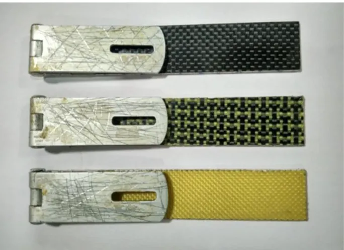
delamination length to avoid large deflections of the specimen extremities, which would invalidate the test. The pre-crack was initiated using a small knife which pulled out the Teflon sheet. The specimen surfaces were scrubbed with sand paper and a thin layer of araldite adhesive was used to fix the piano hinge to the specimen. The samples are painted at one of the longer sides with white paint for proper visibility of crack during the testing. The prepared specimens are shown in Fig. 3.
Fig. 3. Fabricated specimen types. 2.3 Material Testing
Mode I interlaminar fracture toughness tests are conducted for three different sample types, namely carbon/epoxy, aramid/epoxy and carbon-aramid/epoxy composite laminates. The specimens are tested in an electronically controlled universal testing machine according to the standard procedure. Quasi-static force is applied on the specimen and is recorded against the elongation using FSA (Model M100) Universal testing machine, equipped with a load cell of maximum load capacity 100 kN, as shown in Fig. 4. A specimen length of 150 mm was selected and a cross-head speed of 1 mm/min was applied, according to ASTM D5528 [28]. The initial crack length a0 was noted, as responding to the values selected, namely 40 and 42 mm, within an accuracy of 0.1 mm. For the present test, a magnification lens with magnification range up to 10x has been used to track the crack propagation, as shown in Fig. 5. The crack growth from the starter insert was determined by careful inspection of the specimen edge through magnification lens and by observation from force-deflection curve. The specimens are subjected to tensile load until fracture occurs.
Fig. 4. UTM with magnifying lens.
Fig. 5. Development of crack in DCB specimen.
The experiment is repeated for five times each for three types of materials and the average value is considered for discussion.
2.4 Data reduction for mode I interlaminar fracture toughness
The beam theory is modified in terms of P-δ record to calculate the energy release rate. Generally, the energy release rate G in a DCB specimen is related as:
a B G (1)
where B is the specimen width, a is the crack length, while the potential energy Π of a linearly elastic system is:
G
ij ijdv
uP
u
du
0)
(
]
[[
2
1
(2)where Gij and
ij are the stress and strainvector over an infinitesimal element of volume
dv and P(u) is the applied force and depends on displacement function. The initial expression (1) refers to energy due to internal loads in the elastic body and the following expression (2) is the potential work due to application of load. The displacement u is the full opening point for the crack due to the application of load P. The critical strain energy release rate
G
Ic iscalculated from the fracture data of composite DCB specimens by the equation (3):
Ba P BEI a P G cr cr cr Ic
3 2 2 (3)The critical load and corresponding critical deflection of the cantilever section can be calculated by the two equations below from Naik et al. [27]: 1 2 2 r Ic cr Bk a BEI a G P (4) cr r cr
a
P
Bk
EI
a
2 32
3
2
(5)where
P
cr and
cr are critical load andcorresponding critical deflection, respectively. The rotational spring constant kr is obtained
from the fracture data and N is the number of fracture data: 1 1 4 1 2 3 2 ) 3 2 ( 1
N i i N t i cr cr r a a aI a P k (6)The maximum load anticipated during a DCB test of a material with a known modulus, E11,
and the anticipated value of GIC may be
estimated, again by what suggested by Naik et al [27], as: 96 ) 2 ( 3 11 max E h G a B P Ic (7)
2.5 Scanning electronic microscope (SEM)
The DCB fractured sample was studied by using ZEISS EVO MA 15 scanning electron microscope with the magnification range of < 5 – 1,000,000x. The fractured specimens were coated with a gold-sputter over the surface uniformly and to obtain high conductance from SEM observation. The study of interfacial properties, such as matrix crack, fibre pull-out, fibre fracture and
fibre-matrix debonding can be found though the SEM examination. The fractographic analysis is carried out on aramid/epoxy, carbon-aramid/epoxy and carbon/epoxy at different magnification range.
3. RESULTS AND DISCUSSION
The three different composite laminates were considered for mode I interlaminar fracture toughness, such as carbon/epoxy, aramid/epoxy and carbon-aramid/epoxy, at two different pre-crack lengths of ao = 40 mm and ao = 42 mm.
Two very close, yet quite high, pre-crack lengths values have been selected to evaluate the final stage of delamination of the laminates, so to be able to evaluate the maximal energy absorbed during the fracture. Load-deflection curves are obtained from the tests, and are reported in Fig. 6. In general, it was observed that the load varies linearly until reaching the “maximum load” point with stable crack growth propagation. To this, a rapid load drop follows, till reaching a point, after which it decreases with rapid un-stable crack propagation. This is defined as “critical load”, to which corresponds a “critical deflection”. The average values of the maximum load of different composites are reported in Table 2. Hybrid carbon-aramid/epoxy shows a better load carrying capacity compared with carbon/epoxy and aramid/epoxy laminates, although the loss between pre-crack length of 40 and 42 mm is always very significant in the whole extension of the load-deflection curve. In Table 3 the critical deflection of different materials is reported, data which were used for modelling. In particular, modelling, whose results are reported in Fig. 7 as R-curves, which will be discussed below, and summarised with respect to experimental data in Table 4, started for each material at a crack length exceeding the critical deflection, proceeding then up to material failure.
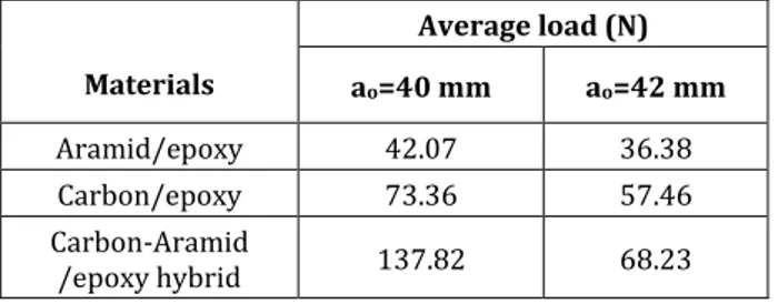
Table 2. Average load of different composites for
different pre-crack length (ao).
Materials Average load (N) ao=40 mm ao=42 mm Aramid/epoxy 42.07 36.38 Carbon/epoxy 73.36 57.46 Carbon-Aramid /epoxy hybrid 137.82 68.23
Table 3. Critical deflection of different composites for
different pre-crack length (ao).
Materials Average load (N) ao=40 mm ao=42 mm Aramid/epoxy 28.4 33.5 Carbon/epoxy 24.3 26.7 Carbon-Aramid /epoxy hybrid 22.3 29.8
Table 4. Fracture toughness of the different
materials with different pre-crack length (ao).
Materials Fracture toughness (J/m2) ao=40 mm ao=42 mm Aramid/epoxy 759.16 688.34 Carbon/epoxy 814.17 596.43 Carbon-Aramid /epoxy hybrid 1239.26 1015.76 0 5 10 15 20 25 30 0 10 20 30 40 50 60 70 80 90 100 110 120 130 140 150 Load (N) Deflection (mm) Aramid/epoxy (a0=40mm) Aramid/epoxy (a0=42mm) Carbon/epoxy (a0=40mm) Carbon/epoxy (a0=42mm) Carbon-aramid/epoxy (a0=40mm) Carbon-aramid/epoxy (a0=42mm)
Fig. 6. Load vs. deflection curves for two different
crack lengths on the three types of laminates.
40 45 50 55 60 65 70 75 80 85 400 450 500 550 600 650 700 750 800 850 900 950 1000 1050 1100 1150 1200 1250 1300 Energy Releas e Ra te G IC ( J/m 2) Crack Length (mm) Aramid/epoxy (a0=40mm) Aramid/epoxy (a0=42mm) Carbon/epoxy (a0=40mm) Carbon/epoxy (a0=42mm) Carbon-Aramid/epoxy (a0=40mm) Carbon-Aramid/epoxy (a0=42mm)
Fig. 7. Comparative curves for Energy Release Rate.
Resistance to the fracture curve (R-curve) for mode I is represented in Fig. 7. The shape of the R-curve may be affected by the fibre bridging phenomenon, as well as by matrix cracking, tow
breaking, multiple delamination and tow bridging in the case of woven fibre composites [30]. In the first case, when the displacement increases, only a small amount of load drop was noted immediately after the first crack onset, although overall a stable crack growth was observed. If fibre bridging has no significant influence on crack growth, the second type features stick-slip behaviour, corresponding to a rapid increase in crack growth and a correlated load drop, occurs after the start of the crack propagation. In this case, a large amount of load drop initiates visually observable unstable crack growth. The unstable crack growth arrests after certain amount of crack extension and may occur again when the load increases, because of coalescence of microcracks, even off-axis with respect to the pre-crack [31]. This sudden drop could be caused therefore by discontinuities in the composite structure, such as geometry pattern of the yarns and weaving defects which act as weakening mechanisms. Fracture toughness values, therefore the initial energy release rates when crack start propagating, are reported in Table 4. Among the three composites, once again, the one that offers the
least percent decrease in fracture toughness when pre-crack is extended from 40 to 42 mm is aramid/epoxy.
Table 5 illustrate the comparison of theoretical and experimentally determined critical load and corresponding critical deflection for all specimens, according to equations (5)-(7) are validated and appear to be very close to the theoretical expression: points were taken at 1 mm intervals in the initial stage of crack growth, and at 5 mm intervals for higher crack growths. The maximum energy release shown by the hybrid laminates was compared to what measured by Kim et al [32] and showed a 44 % increment in total energy release rate, which was attributed to the intraply structure, resulting in a 3.62 mm fibre yarn incremented width. The values used in the analysis are the dimensional parameters of the samples (lay-up [0º/90º]14, B=25mm, 2h=3.08mm). The only
variables differing between the materials are pre-crack length ao, Young’s modulus E and
elastic spring constant kr, which are specified in
each case in the caption.
Table 5. Mode I delamination tests and numerical analysis results.
a. Aramid/epoxy (ao=40 mm, E=18.95 GPa, kr=20.48 N-m)
Test Results Numerical Analysis
Crack length
a (mm) P (N) Load Deflection δ (mm) Critical Load Pcr (N)
Critical deflection
δcr (mm)
Maximum load
Pmax (N)
Energy release rate
GIc (J/m2) 55 42.07 8.8 39.90 12.68 47.26 602.25 56 41.16 9.9 38.95 13.33 45.95 609.89 57 40.21 10.5 39.04 13.99 44.70 614.84 58 39.45 11.4 37.18 14.67 43.53 624.25 59 38.67 12.3 36.35 15.36 42.41 631.79 64 34.12 14.1 32.72 19.07 37.59 626.06 69 31.08 16.2 29.75 23.16 33.76 644.24 74 30.01 21.3 27.28 27.63 30.63 729.48 79 28.02 26.4 25.19 32.48 28.03 759.16
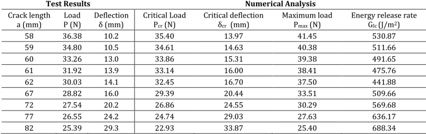
b. Aramid/epoxy (ao=42 mm, E=18.95 GPa, kr=20.48 N-m)
Test Results Numerical Analysis
Crack length
a (mm) P (N) Load Deflection δ (mm) Critical Load Pcr (N)
Critical deflection
δcr (mm)
Maximum load
Pmax (N)
Energy release rate
GIc (J/m2) 58 36.38 10.2 35.40 13.97 41.45 530.87 59 34.80 10.5 34.61 14.63 40.38 511.66 60 33.26 13.0 33.86 15.31 39.38 491.65 61 31.92 13.9 33.14 16.00 38.41 475.76 62 30.03 14.1 32.45 16.70 37.50 441.88 67 28.82 16.0 29.39 20.44 33.51 509.66 72 27.54 20.2 26.86 24.55 30.29 569.68 77 26.55 24.2 24.74 29.03 27.63 636.17 82 25.39 29.3 22.93 33.87 25.40 688.34
c. Carbon/epoxy (ao=40 mm, E=46 GPa, kr=83.47 N-m)
Test Results Numerical Analysis
Crack length
a (mm) P (N) Load Deflection δ (mm) Critical Load Pcr (N)
Critical deflection
δcr (mm)
Maximum load
Pmax (N)
Energy release rate
GIc (J/m2) 49 73.36 4.8 81.06 5.39 92.03 517.25 50 67.52 5.2 78.65 5.74 88.97 468.92 51 67.84 5.4 76.38 6.09 86.10 505.46 52 65.03 5.6 74.24 6.45 83.40 494.90 53 64.27 5.8 72.22 6.82 80.88 514.08 58 61.42 8.2 63.57 8.84 70.23 622.55 63 56.36 9.7 56.78 11.11 62.07 671.22 68 52.21 11.1 51.30 13.63 55.60 717.76 73 50.36 13.3 46.79 16.41 50.36 814.17
d. Carbon/epoxy (ao=42 mm, E=46 GPa, kr=83.47 N-m)
Test Results Numerical Analysis
Crack length
a (mm) P (N) Load Deflection δ (mm) Critical Load Pcr (N)
Critical deflection δcr
(mm) Maximum load Pmax (N)
Energy release rate
GIc (J/m2) 55 57.46 6.2 58.62 6.50 65.27 462.23 56 56.92 6.5 57.14 6.85 63.45 479.87 57 55.15 6.8 55.74 7.20 61.74 475.86 58 54.63 7.1 54.41 7.56 60.11 492.51 59 53.20 7.4 53.14 7.94 58.57 491.97 64 48.74 8.3 47.58 9.92 51.92 525.61 69 45.53 10.4 43.08 12.13 46.62 568.82 74 41.41 11.6 39.35 14.55 42.30 571.46 79 38.72 `13.3 36.23 17.19 38.72 596.43
e. Carbon-Aramid/epoxy (ao=40 mm, E=39 GPa, kr=37.83 N-m)
Test Results Numerical Analysis
Crack length
a (mm) Load P (N) Deflection δ (mm) Critical Load Pcr (N)
Critical deflection δcr
(mm) Maximum load Pmax (N)
Energy release rate
GIc (J/m2) 42 137.82 2.9 105.26 5.21 137.82 1239.26 43 93.94 3.6 101.61 5.61 131.83 629.89 44 93.86 4.8 98.20 6.04 126.33 684.03 45 93.24 4.8 95.03 6.47 121.28 732.45 46 92.16 5.7 92.06 6.92 116.61 773.97 51 82.92 7.4 79.66 9.37 97.80 890.70 56 69.78 10.6 70.26 12.17 84.22 850.70 61 63.18 13.1 62.86 15.32 73.95 904.52 66 61.53 15.6 56.89 18.80 65.91 1079.89
f. Carbon-Aramid/epoxy hybrid (ao=42 mm, E=39 GPa, kr=37.83 N-m)
Test Results Numerical Analysis
Crack length
a (mm) P (N) Load Deflection δ (mm) Critical Load Pcr (N)
Critical deflection δcr
(mm) Maximum load Pmax (N)
Energy release rate
GIc (J/m2) 51 68.23 7.6 72.12 8.49 88.55 603.07 52 65.46 9.0 70.24 8.97 85.78 591.48 53 65.21 10.1 68.45 9.46 83.18 624.23 54 64.86 10.8 66.76 9.97 80.73 655.54 55 64.52 11.4 65.14 10.49 78.43 587.41 60 60.38 14.0 58.13 13.27 68.62 786.32 65 58.63 17.0 52.50 16.36 61.00 938.33 70 53.12 20.5 47.87 19.77 54.90 950.93 75 49.91 22.4 44.00 23.48 49.91 1015.76
The fractographic analysis was aimed at examining the peculiarities of damage accumulation in the samples. For this purpose, different DCB tested samples are considered, such as aramid/epoxy, carbon-aramid/epoxy and carbon/epoxy, and observed at different magnification range and with
different pre-crack lengths. The aramid/epoxy sample presented in Fig. 8 indicates a poor fibre/matrix adhesion and also some broken fibres are present in fracture surface. This may be the main cause of offering the lowest fracture toughness between the composites.
Fig. 8. SEM micrographs of the fractured surface of an
aramid/epoxy specimen.
The intra-ply hybrid carbon-aramid/epoxy fractured surface shown in Fig. 9 illustrates that there is a good bonding between fibre and matrix and the resin appears to flow effectively to embed the fibres.
Fig. 9. SEM micrographs of the fractured surface of a
carbon-aramid/epoxy hybrid specimen.
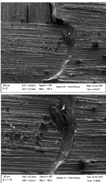
Fig. 10. SEM micrographs of fractured surface of a
carbon/epoxy specimen.
The cleavage failure was caused because of opening displacement for carbon/epoxy laminate, as shown in Fig. 10.
a) b) c)
Fig. 11. Images of fibre bridging effect on different specimens: a) aramid/epoxy; b) carbon aramid/epoxy hybrid;
and c) carbon/epoxy.
The fibre bridging effect on aramid/epoxy, carbon-aramid/epoxy, is shown in Figs. 11a, 11b and 11c: in particular, aramid/epoxy expresses poor fibre bridging effect as compared to other combinations as far as the length of the delaminated surface interested is involved.
a) b)
c) d)
e) f)
Fig. 12. Fractured surfaces of different specimens:
(a-b) aramid/epoxy; (c-d) carbon-aramid/epoxy hybrid; (e-f) carbon/epoxy.
The fractured surfaces are illustrated in Fig. 12, which shows that the hybrid has better peel-out resisting capacity when compared to other combinations, since it tends to disperse fracture damage across the whole surface, resulting in an improved resistance to it. Possible developments of the indication supplied in this study would be achieving a large scale bridging effect [33], which is so far confined to carbon
fibre composites and not to aramid fibre ones. This is especially useful in view of the promising energy absorption characteristics shown by carbon/aramid hybrids in sectors, such as automotive applications [34].
4. CONCLUSIONS
The effect of intraply hybridization on mode I interlaminar fracture response was evaluated in double cantilever beam (DCB). It can be concluded from the results that intra-ply carbon-aramid/epoxy composites material carries maximum GIc value of 1239 J/m2 as compared to carbon/epoxy 814 J/m2 and aramid/epoxy 749 J/m2. Intra-ply composition shows excellent delamination resistance when compared with aramid /epoxy and carbon/epoxy laminates, which may be due to the bridging effect. Intra-ply hybrid shows also good crack stopping ability together with strong fibre/matrix interface. This suggests that, due to fibre bridging, intraply hybrid could be more effective in terms of fracture resistance due to dissipation of fracture energy less concentrated across the sample than in both the originating composites.
Acknowledgement
The authors would like to thank the University Grants Commission (UGC), Government of India, for its financial support to this international collaboration. REFERENCES
[1] M.N. Gururaja, A.N. Hari Rao, A Review on Recent
Applications and Future Prospectus of Hybrid Composites, International Journal of Soft
Computing and Engineering, vol. 1, no. 6, pp. 352-355, 2012.
[2] H. Saghafi, M. Fotouhi, G. Minak, M. Saeedifar,
Improvement of the impact properties of composite laminates by means of nano-modification of the
Nanotechnology and Applied Nanosciences, vol. 8, no.12, pp. 2406, 2018, doi: 10.3390/app8122406 [3] C. Fragassa, Marine applications of natural
fibre-reinforced composites: A manufacturing case study,
in E. Pellicer et al. (Ed.): Advances in applications of industrial biomaterials, Springer, pp. 21-47, 2017, doi: 10.1007/978-3-319-62767-0
[4] C. Fragassa, A. Pavlovic, C. Santulli, Mechanical and
impact characterisation of flax and basalt fibre vinylester composites and their hybrids, Composites
Part B: Engineering, vol. 137, pp. 247-259, 2018, doi: 10.1016/j.compositesb.2017.01.004
[5] M.T. Dehkordi, H. Nosraty, M.M. Shokrieh, G. Minak, D. Ghelli, Low velocity impact properties
of intraply hybrid composites based on basalt and nylon woven fabrics, Materials and Design, vol.
31, no. 8, pp. 3835–3844, 2010.
[6] M.T. Dehkordi, H. Nosraty, M.M. Shokrieh, G. Minak, D. Ghelli, The influence of hybridization
on impact damage behaviour and residual compression strength of intraply basalt/nylon hybrid composites, Materials and Design, vol. 43,
pp. 283-290, 2013, doi:
10.1016/j.matdes.2012.07.005
[7] C.C. Chamis, R.F. Lark, J.H. Sinclair, Mechanical
property characterization of intraply hybrid composites, Pentagon Report No. A301566,
1979, doi: 10.1520/STP29315S
[8] A. Pegoretti, E. Fabbri, C. Migliaresi, F. Pilati,
Intraply and interply hybrid composites based on E-glass and poly (vinyl alcohol) woven fabrics: tensile and impact properties, Polymer
International, vol. 53, no. 9, pp. 1290-1297, 2004, doi: 10.1002/pi.1514
[9] Q. Zeng, X. Huang, X. Lin, Study on stress
concentrations in an intraply hybrid composite sheet, Applied Mathematics Mechanics, vol. 22,
no. 2, pp. 154–159, 2001.
[10] M.A. Attia, M.A. Abd El-baky, A.E. Alshorbagy,
Mechanical Performance of Intraply and Inter-Intraply hybrid composites based on E-glass and Polypropylene unidirectional fibers, Journal of
Composite Materials, vol. 51, no. 3, pp. 381–394, 2017, doi: 10.1177/0021998316644972 [11] B. Nageswara Rao, A.R. Acharya, Evaluation of
fracture energy, GIc, using a double cantilever beam fibre composite specimen, Engineering
Fracture Mechanics, vol. 51, no. 2, pp. 317–322, 1995, doi: 10.1016/0013-7944(94)00251-C [12] R.H. Truss, P.J. Hine, R.A. Duckett, Interlaminar and
intralaminar fracture toughness of uniaxial continuous and discontinuous carbon fibre/epoxy composites, Composites Part A, vol. 28A, pp. 627–
636, 1997, doi: 10.1016/S1359-835X(97)00019-5
[13] B.J. Briscoe, D.R. Williams, Interlaminar fracture
toughness of aramid/epoxy laminates, Composites
Science and Technology vol. 46, pp. 277-286, 1993, doi: 10.1016/0266-3538(93)90161-9 [14] A. Laksimi, M.L. Benzeggagh, G. Jing, M. Hecini
J.M. Roelandt, Mode I interlaminar fracture of
symmetrical cross-ply laminates, Composites
Science and Technology, vol. 41, pp. 147–164, 1991, doi: 10.1016/0266-3538(91)90025-K [15] J.J. Polaha, B.D. Davidson, R.C. Hudson, A.
Pieracci. Effect of mode ratio, ply orientation and
precracking on the delamination toughness of a laminated composite, Journal of Reinforced
Plastics and Composites, vol. 15, pp. 141-173, 1996, doi: 10.1177/073168449601500202 [16] F. Bensadoun, I. Verpoest, A.W. Van Vuure,
Interlaminar fracture toughness of flax-epoxy composites, Journal of Reinforced Plastics and
Composites, vol. 36, pp. 121–136, 2017, doi: 10.1177%2F0731684416672925
[17] D. Fanteria, L. Lazzeri, E. Panettieri, U. Mariani, M. Rigamonti, Experimental characterization of the
interlaminar fracture toughness of a woven and a unidirectional carbon/epoxy composite, Composites
Science and Technology, vol. 142, pp. 20-29, 2017, doi: 10.1016/j.compscitech.2017.01.028
[18] Y. Zhu, Characterization of interlaminar fracture
toughness of a carbon/epoxy composite material.
Master thesis, The Pennsylvania State University, State College, 2009.
[19] P. Davies, H.H. Kausch, J.G. Williams, et al.,
Round-robin interlaminar fracture testing of carbon-fibre-reinforced epoxy and PEEK composites, Composites
Science and Technology, vol. 43, pp. 129–136, 1992, doi: 10.1016/0266-3538(92)90003-L [20] K. Trakas, M.T. Kortschot, The Relationship
between Critical Strain Energy Release Rate and Fracture Mode in Multidirectional Carbon-Fiber/Epoxy Laminates, Composite Materials:
Fatigue and Fracture, vol. 6, pp. 283-304, 1997. [21] S. Foster, P. Robinson, J.M. Hodgkinson,
Interlaminar fracture toughness testing of 0 deg/θ deg interfaces in carbon-epoxy laminates using edge delaminated strategy, Plastics Rubber
and Composites, vol. 26, pp. 430-437, 1997. [22] J. Tao, C.T. Sun, Influence of Ply Orientation on
Delamination Composite Laminates, Journal of
Composite Materials, vol. 31, pp. 1933-1947, 1998, doi: 10.1177/002199839803202103 [23] Z. Yang, C.T. Sun, Interlaminar fracture
toughness of a graphite/epoxy multidirectional composite, Journal of Engineering Materials and
Technology, vol. 122, no. 4, pp. 428-433, 2000, doi: 10.1115/1.1289027
[24] A.B. Pereira, A.B. de Morais, Mode-I interlaminar
fracture of carbon/epoxy multidirectional
laminates, Composites Science and Technology, vol. 64, no. 13-14, pp. 2261-2270, 2004, doi: 10.1016/j.compscitech.2004.03.001
[25] X.N. Huang, D. Hull, Effects of fibre bridging on
GIC of a unidirectional glass/epoxy composite,
Composites Science and Technology, vol. 35, no. 3, pp. 283-299, 1989, doi: 10.1016/0266-3538(89)90040-7
[26] M. Fotouhi, P. Suwarta, M. Jalalvand, G. Czél, M. R. Wisnom, Acoustic Emission Monitoring of Thin Ply
Hybrid Composites under Repeated Quasi-Static Tensile Loading, FME Transactions, vol. 46, pp.
238-244, 2018, doi: 10.5937/fmet1802238F [27] Hyseni A., De Paola S., Minak G., Fragassa C,
Mechanical characterization of ecocomposites, in
30th Danubia-Adria Symposium on Advances in Experimental Mechanics, September 25-28, 2013, DAS 2013, Primosten, Croatia, pp. 175-176. [28] ASTM Standard D 5528-94a. Standard Test
Method for Mode I Interlaminar Fracture Toughness of Unidirectional Fiber Reinforced polymer Matrix Composites, ASTM Annual Book
of Standards, 15.03, p. 272–81, 1994 .
[29] R.A. Naik, J.H. Crews, K.N. Shivakumar, Effects of
T-Tabs and Large Deflections in DCB Specimen Tests, in T. K. O’Brien (Ed.): Composite
Materials; Fatigue and Fracture, Third Volume, American Society for Testing and Materials, pp. 169–186, 1991.
[30] Z. Suo, G. Bao, B. Fan, Delamination R-curve
phenomena due to damage, Journal of the
Mechanics and Physics of Solids, vol. 40, no. 1, pp. 1-16, 1992, doi: 10.1016/0022-5096(92)90198-B [31] L. Asp, A. Sjögren, E. Greenhalgh, Delamination
growth and thresholds in a carbon/epoxy composite under fatigue loading, Journal of
Composites, Technology and Research, vol. 23, no. 2, pp. 55-68, 2001, doi: 10.1520/CTR10914J [32] S.C. Kim, J.S. Kim, H.J. Yoon, Experimental and
numerical investigation of mode I delamination behaviours of woven fabric composites with carbon, Kevlar and their hybrid fibers, International Journal
of Precision Engineering and Manufacturing, vol. 2, no. 2, pp. 321-329, 2011.
[33] B.F. Sørensen, T.K. Jacobsen, Large-scale
bridging in composites: R-curves and bridging laws, Composites Part A, vol. 29, no. 11, pp.
1443-1451, 1998, doi: 10.1016/S1359-835X(98)00015-6
[34] Y. Ma, T. Sugahara, Y. Yang, H. Hamada, A study on
the energy absorption properties of carbon/aramid fiber filament winding composite tube, Composite
Structures, vol. 123, pp. 301-311, 2015, doi: 10.1016/j.compstrucut.2014.12.067