Università degli Studi di Ferrara
DOTTORATO DI RICERCA IN SCIENZE
DELL’INGEGNERIA (CURRICULUM CIVILE)
CICLO XXI° - COORDINATORE Prof. Stefano Trillo
Universitat Politècnica de Catalunya
DOCTORAT EN ANÀLISI ESTRUCTURAL
COORDINADOR Prof. Alex Barbat
CONTINUUM DAMAGE MODEL
FOR NONLINEAR ANALYSIS
OF MASONRY STRUCTURES
Settore Scientifico Disciplinare ICAR/09
Dottorando Tutori
Dott. Ing. Pelà Luca Prof. Ing. Aprile Alessandra
Prof. Ing. Cervera Miguel
Look ahead, and even when you think you are looking ahead, look even more ahead.
Doctoral Thesis submitted in fulfilment of the requirements for the Degree of Doctor of Philosophy
International Ph.D. Program:
Universitat Politècnica de Catalunya
Departament de Resistència de Materials i Estructures a l'Enginyeria Doctorat en Análisi Estructural
Università degli Studi di Ferrara Dipartimento di Ingegneria
Dottorato di Ricerca in Scienze dell’Ingegneria Civile
Thesis Supervisors:
Prof. Miguel Cervera - Universitat Politècnica de Catalunya, Spain Prof. Alessandra Aprile - Università degli Studi di Ferrara, Italy
Public Defence: Ferrara, Italy, March 26, 2009
Board of Examiners:
Prof. Antonio Tralli - Università degli Studi di Ferrara, Italy Prof. Miguel Cervera - Universitat Politècnica de Catalunya, Spain Prof. Pere Roca - Universitat Politècnica de Catalunya, Spain
Prof. Andrea Benedetti - Alma Mater Studiorum Università di Bologna, Italy Prof. Giorgio Vassena - Università degli Studi di Brescia, Italy
European Referees (for the Doctor Europaeus Mention):
Prof. Sergio Oller - Universitat Politècnica de Catalunya, Spain Prof. Rui Faria - Universidade do Porto, Portugal
Acknowledgments
The research reported in this thesis has been carried out at the Department of Strength of Materials and Structural Engineering (RMEE) of the Technical University of Catalonia and at the Department of Engineering (ENDIF) of the University of Ferrara. The aforementioned Universities subscribed a co-tutoring agreement, with the aim of formalising the international co-tutorship of this Doctoral Thesis.
The work reported in this thesis has been possible thanks to the scholarship made available by the University of Ferrara. Additional financial support by the same University is gratefully acknowledged.
The studies presented here have been developed within the research project BIA2006-04127 funded by DGE of the Spanish Ministry of Science and Technology, whose assistance is gratefully acknowledged.
The work has been performed under the guidance of Prof. Miguel Cervera and the supervision of Prof. Pere Roca and Prof. Andrea Benedetti.
I am very grateful to Prof. Cervera for his continuous helpfulness, his wise advice and his sincere incitement during all the research. Thanks also for proposing me to do a prestigious international Ph.D.
I would like to thank Prof. Roca for his valuable advice and all the helpful support he gave me during my long stay in Barcelona.
I gratefully acknowledge the priceless help of Prof. Andrea Benedetti and Prof. Alessandra Aprile, expressed in the form of so many suggestions and fruitful discussions. Moreover, they gave me the precious opportunity to continue my studies. This led me to a memorable international experience. Their friendship and support are definitely very important for me. I gratefully acknowledge the always helpful suggestions contributed by Prof. Antonio Tralli and Prof. Sergio Oller on many occasions.
I would like to record my thanks to Prof. Evelina Lamma and to Lena Fabbri, who devoted a lot of energies to define the co-tutoring agreement between the UNIFE and the UPC. I would like also to acknowledge Rosa Maria Olea, Felicidad Leiva and Ángela Navarro of
the UPC, as well as the coordinator of the Ph.D. Program of the Engineering Department of Ferrara, Prof. Stefano Trillo.
I am grateful to all my kind colleagues of the Department of Construction Engineering of Barcelona, particularly to Cristian, Álvaro and Guillermo for their support and sincere friendship. I have also a happy memory of professors and students I met at the UIS University, in Colombia.
I must acknowledge Roberto Clemente for all the material provided in order to help me to handle the tracking algorithm. Thanks also to Michele Chiumenti for providing me the COMET package.
A special thanks goes out to my friends and colleagues of the Department of Engineering of Ferrara, i.e. Monia, Stefania, Marco, Valerio, Anna, Alessio, Giovanni, Chiara, Reyna, Agnese, Tommaso, Sara, Stefano, Alessandro and Luisfilippo.
I have no words to thank my best friends in Barcelona, Beniamino, Rubén, Flaminio, Marc and Hiram. Although I met them only 2 years ago, they are now like brothers for me, and I really doubt that I will ever be able to fully convey my gratitude to them. Thanks also to Marina and her family, Alberto and Anna, Sergio and Teresa, Cristina, Sonia, Elvira, Leo, Dani, Guillermo, Miriam, Luisa, Gerard and Jordi.
A very special thanks goes out to all my Italian friends, in particular to Enrico, Alessandro, Alessio and Davide. We have always shared good times and unforgettable happy moments. They have been, are and always will be my reference point.
Finally, a very special thanks goes out to my family, Mario, Marisa, Claudia, Tina and Isolda. Thanks God for giving me such a beautiful family. They gave me the education and handed down the most important life values. They taught me the love of knowledge. They have always encouraged and helped me a lot, even when I was far from home. I love you. My gratitude to Chiara, my girlfriend, cannot be expressed in few words… her love, patience and support in whatever I do are things that I will never forget.
Abstract
The present work focuses on the formulation of a Continuum Damage Mechanics model for nonlinear analysis of masonry structural elements. The material is studied at the macro-level, i.e. it is modelled as a homogeneous orthotropic continuum.
The orthotropic behaviour is simulated by means of an original methodology, which is based on nonlinear damage constitutive laws and on the concept of
mapped tensors from the anisotropic real space to the isotropic fictitious one. It is
based on establishing a one-to-one mapping relationship between the behaviour of an anisotropic real material and that of an isotropic fictitious one. Therefore, the problem is solved in the isotropic fictitious space and the results are transported to the real field. The application of this idea to strain-based Continuum Damage Models is rather innovative.
The proposed theory is a generalization of classical theories and allows us to use the models and algorithms developed for isotropic materials. A first version of the model makes use of an isotropic scalar damage model. The adoption of such a simple constitutive model in the fictitious space, together with an appropriate
Abstract ii
definition of the mathematical transformation between the two spaces, provides a damage model for orthotropic materials able to reproduce the overall nonlinear behaviour, including stiffness degradation and strain-hardening/softening response. The relationship between the two spaces is expressed in terms of a transformation
tensor which contains all the information concerning the real orthotropy of the
material. A major advantage of this working strategy lies in the possibility of adjusting an arbitrary isotropic criterion to the particular behaviour of the orthotropic material. Moreover, orthotropic elastic and inelastic behaviours can be modelled in such a way that totally different mechanical responses can be predicted along the material axes.
The aforementioned approach is then refined in order to account for different behaviours of masonry in tension and compression. The aim of studying a real material via an equivalent fictitious solid is achieved by means of the appropriate definitions of two transformation tensors related to tensile or compressive states, respectively. These important assumptions permit to consider two individual damage criteria, according to different failure mechanisms, i.e. cracking and crushing. The constitutive model adopted in the fictitious space makes use of two scalar variables, which monitor the local damage under tension and compression, respectively. Such a model, which is based on a stress tensor split into tensile and compressive contributions that allows the model to contemplate orthotropic induced damage, permits also to account for masonry unilateral effects. The orthotropic nature of the Tension-Compression Damage Model adopted in the fictitious space is demonstrated. This feature, both with the assumption of two distinct damage criteria for tension and compression, does not permit to term the fictitious space as “isotropic”. Therefore, the proposed formulation turns the original concept of “mapping the real space into an isotropic fictitious one” into the innovative and more general one of “mapping the real space into a favourable
Abstract iii
(or convenient) fictitious one”. Validation of the model is carried out by means of comparisons with experimental results on different types of orthotropic masonry. The model is fully formulated for the 2-dimensional case. However, it can be easily extended to the 3-dimensional case. It provides high algorithmic efficiency, a feature of primary importance when analyses of even large scale masonry structures are carried out. To account for this requisite it adopts a strain-driven formalism consistent with standard displacement-based finite element codes. The implementation in finite element programs is straightforward.
Finally, a localized damage model for orthotropic materials is formulated. This is achieved by means of the implementation of a crack tracking algorithm, which forces the crack to develop along a single row of finite elements. Compared with the smeared cracking approach, such an approach shows a better capacity to predict realistic collapsing mechanisms. The resulting damage in the ultimate condition appears localized in individual cracks. Moreover, the results do not suffer from spurious mesh-size or mesh-bias dependence. The numerical tool is finally validated via a finite element analysis of an in-plane loaded masonry shear wall.
Abstract iv
Resumen
En el presente trabajo se plantea la formulación de un modelo basado en la Mecánica del Daño Continuo aplicado al análisis no lineal de estructuras de obra de fábrica. El material se estudia a nivel macroscópico y se modela como un continuo homogéneo y ortótropo.
La ortotropía del comportamiento se simula por medio de una metodología original, basada en leyes constitutivas no lineales y en el concepto de tensores
transformados desde el espacio real anisótropo a un espacio ficticio isótropo. En
detalle, se establece una transformación entre el comportamiento de un sólido real anisótropo y el de un sólido ficticio isótropo. De esta manera el problema se resuelve en el espacio ficticio isótropo y los resultados se retraen al espacio real. La aplicación de dicho planteamiento a Modelos de Daño Continuo basados en deformaciones es muy innovadora.
La teoría propuesta es una generalización de las teorias clásicas y permite utilizar modelos y algoritmos formulados para materiales isótropos. Una primera versión del modelo considera un modelo de daño escalar e isótropo. La adopción de este modelo simple en el espacio ficticio, junto a la apropriada definición de la
Resumen vi
transformación matemática entre los dos espacios, conduce a un modelo de daño para materiales ortótropos capaz de reproducir el comportamiento no lineal global, incluyendo degradación de rigidez y leyes de endurecimiento/ablandamiento. La relación entre los dos espacios está expresada en términos de un tensor de
transformación que contiene toda la información sobre la real ortotropía del
material. Una ventaja muy importante de esta estrategía reside en la posibilidad de ajustar cualquier criterio de daño al comportamiento particular del material ortótropo. Además, se pueden modelar comportamientos elásticos e inelásticos totalmente diferentes a lo largo de los ejes del material.
El procedimiento mencionado anteriormente se refina después para reproducir los diferentes comportamientos a tracción y a compresión. El objetivo de estudiar un material real por medio de un sólido equivalente ficticio se logra a través de las definiciones de dos tensores de transformación relacionados a estados de tensión y compresión, respectivamente. Estos importantes supuestos permiten considerar dos criterios de daño distintos de acuerdo con diferentes mecanismos de fallo, es decir fisuración y aplastamiento. El modelo constitutivo contemplado en el espacio ficticio considera dos variables para controlar respectivamente el daño local a tracción y compresión. Dicho modelo, que está basado en una descomposición del tensor de tensión en componentes positivas y negativas que hace que el modelo induzca una degradación ortótropa, permite también representar el caracter unilateral del daño. Se demuestra el carácter ortótropo del Modelo de Daño Tensión-Compresión contemplado en el espacio ficticio. Este último aspecto, juntamente al hecho de considerar dos criterios de daño distintos en tracción y en compresión, no permite denominar el espacio ficticio como “isótropo”. Por lo tanto, la formulación planteada en este trabajo cambia el concepto original de “transformar el espacio real en uno ficticio isótropo” en el concepto innovador y más general de “transformar el espacio real en uno ficticio oportunamente
Resumen vii
comparación con resultados experimentales de diversos ensayos sobre obra de fábrica ortótropa.
El modelo está formulado para el caso bidimensional. Sin embargo, es posible su extensión al caso 3D. Se observa una considerable eficiencia computacional, muy importante para el análisis de estructuras complejas de obra de fábrica. Este requisito se debe al favorable formato en deformaciones, compatible con programas de elementos finitos estándar basados en desplazamientos. La implementación en codigos de elementos finitos es relativamente simple.
Finalmente, se plantea la formulación de un modelo de daño localizado para
materiales ortótropos. Se utiliza un algoritmo de rastreo de fisuras, que fuerza la
fisura a desarrollarse a lo largo de una fila singular de elementos finitos. Su comparación con el enfoque de fisura distribuida evidencia una mejor capacidad de predecir mecanismos de fallo realistas. El daño correspondiente a condiciones últimas se modela mediante fisuras localizadas. Además, los resultados no dependen ni del tamaño de los elementos finitos utilizados en la discretización espacial, ni de la orientación de la malla. El proceso de validación de la herramienta numérica se lleva a cabo mediante el análisis por el método de elementos finitos de una pared de obra de fábrica sometida a cargas verticales y horizontales.
Resumen viii
Sommario
Questo lavoro presenta la formulazione di un modello basato sulla Meccanica del Danneggiamento dei Solidi Continui, finalizzato all’analisi non lineare di elementi strutturali in muratura. Il materiale viene studiato da un punto di vista macroscopico e modellato come un continuo omogeneo ortotropo.
Il comportamento ortotropo viene simulato per mezzo di una metodologia originale, basata su leggi costitutive non lineari e sul concetto di tensore mappato dallo spazio reale anisotropo ad uno spazio fittizio isotropo. In pratica, si stabilisce una trasformazione tra il comportamento di un solido reale anisotropo e quello di uno fittizio isotropo; di conseguenza, il problema viene risolto nello spazio fittizio isotropo e i risultati ricondotti al campo reale. L’applicazione di questa idea a modelli di danno continuo formulati in deformazioni è piuttosto innovativa.
La teoria proposta è una generalizzazione delle teorie classiche e permette l’utilizzo di modelli e algoritmi sviluppati per materiali isotropi. Una prima versione del modello utilizza una legge costitutiva di danno isotropo scalare. Tale semplice assunzione nello spazio fittizio, assieme ad un’appropriata definizione della trasformazione matematica tra i due spazi, fornisce un modello di danno per
Sommario x
materiali ortotropi in grado di riprodurre il comportamento non lineare globale, tenendo in conto la degradazione della rigidezza e leggi di hardening/softening non lineari. La relazione tra i due spazi si esprime per mezzo di un tensore di
trasformazione che contiene tutta l’informazione sull’ortotropia reale del materiale.
Uno dei vantaggi principali di tale metodologia risiede nella possibilità di aggiustare un qualsiasi criterio di danno isotropo al comportamento particolare del materiale ortotropo. In aggiunta, è possibile modellare il comportamento elastico ed anelastico in modo tale da riprodurre risposte meccaniche completamente differenti lungo gli assi del materiale.
L’approccio summenzionato viene successivamente raffinato, in maniera tale da includere la descrizione del diverso comportamento a trazione e a compressione. L’obiettivo di studiare un materiale reale per mezzo di un solido equivalente fittizio viene raggiunto mediante l’appropriata definizione di due tensori di trasformazione relazionati, rispettivamente, a stati di trazione e compressione. Tali importanti assunzioni permettono di considerare due criteri di danno indipendenti, coerentemente a due diversi meccanismi di rottura, ossia fessurazione e schiacciamento. Il modello costitutivo adottato nello spazio fittizio è caratterizzato dall’uso di due variabili scalari che controllano, rispettivamente, il danno locale a trazione e compressione. Tale modello, basato su una decomposizione del tensore degli sforzi nelle sue componenti di trazione e compressione, che permette di contemplare l’anisotropia indotta per danneggiamento, include anche la descrizione del carattere unilaterale del danno. La natura ortotropa del Modello di Danno Tensione-Compressione adottato nello spazio fittizio viene inoltre dimostrata. Quest’ultimo aspetto, assieme all’assunzione di due distinti criteri di danneggiamento per stati di trazione e compressione, non permette di denominare lo spazio fittizio come “isotropo”. Pertanto, la formulazione proposta in questo lavoro cambia il concetto originario di “mappare lo spazio reale in uno isotropo fittizio” in quello innovativo e più generale di “mappare lo spazio reale in uno
Sommario xi
fittizio convenientemente opportuno”. La validazione del modello viene eseguita attraverso un attento confronto con risultati sperimentali su differenti tipi di murature, caratterizzate anche da elevati gradi di ortotropia.
La formulazione completa del modello viene presentata per il caso bidimensionale; ciononostante, è facilmente possibile estrapolare quella tridimensionale. Il modello è caratterizzato da un’alta efficienza computazionale, una caratteristica di primaria importanza nel campo dell’analisi di strutture in muratura anche complesse. A tal fine, viene adottato un vantaggioso formato in deformazioni, pienamente compatibile con i programmi ad elementi finiti standard. L’implementazione del modello in codici ad elementi finiti è relativamente semplice e viene descritta in dettaglio.
Infine, si presenta la formulazione di un modello di danno localizzato per materiali
ortotropi, ottenuta per mezzo dell’implementazione di un algoritmo di crack-tracking, che forza la fessura a localizzarsi lungo una singola fila di elementi finiti.
Confrontato con il tradizionale approccio alle fessure distribuite, il modello proposto presenta una maggiore capacità di prevedere meccanismi di collasso realistici: il danno risultante in condizioni ultime appare localizzato in fessure discrete. Inoltre, i risultati sono oggettivi al variare delle dimensioni degli elementi finiti e dell’inclinazione della mesh adottata nel problema discreto. La validazione del modello numerico viene condotta per mezzo dell’analisi agli elementi finiti di una parete a taglio in muratura caricata nel piano.
Sommario xii
Contents
Chapter 1. Introduction 1
1.1 Overview of Computational Modelling of Masonry
Structures………... 3
1.2 Masonry Material: Principal Features……… 15
1.3 Aim and Objectives of the Thesis……….. 25
1.4 Outline of the Thesis………... 26
Chapter 2. Overview of Continuum Damage Mechanics and
Damage Models
29
2.1 Continuum Damage Mechanics: Background and Basics….. 31
2.1.1 Damage Variable……… 33
2.1.2 Effective Stress Concept and Principle of Strain- Equivalence………….……….….. 36
Contents xiv
2.1.3 Thermodynamic Framework…….………... 40
2.2 Brief Overview of Damage Models……….... 43
2.3 Scalar Damage Models………... 46
2.3.1 Thermodynamic Formulation………. 46
2.3.2 Damage Threshold Function……….. 48
2.3.3 Damage Evolution Law………... 50
2.3.4 Tangent Constitutive Tensor……….. 51
2.3.5 Numerical Implementation………. 52
2.3.6 Different Damage Criteria…….………. 53
2.4 Unilateral Effect and Damage Models……… 57
2.4.1 Tension-Compression Damage Model (Faria et al., 1998)……….. 58
2.4.2 Numerical Implementation………. 63
2.4.3 Comparison with Others Formulations………... 66
2.4.4 Extension to Account for Plastic Strains……… 70
2.5 Conclusions………. 73
Chapter 3. Scalar Damage Model for Orthotropic Materials
77
3.1 Orthotropic Elastic Behaviour………. 793.1.1 Coordinate Systems………. 80
3.1.2 Stress-Strain Equations………... 81
3.1.3 Coordinate Transformations……… 84
3.2 Formulation of the Model……… 88
3.2.1 Definition of the Space Transformation Tensors…… 90
3.3 Underlying Fictitious Damage Model………. 98
Contents xv
3.3.2 Evolution of the Damage Variable. Inelastic
Behaviour……… 102 3.3.3 Tangent and Secant Operators……… 106 3.4 Orthotropic Softening Behaviour……… 107 3.5 Numerical Implementation of the Proposed Model………… 109 3.6 Numerical Examples………... 111 3.6.1 Behaviour of the Model. Elemental Test……… 112 3.6.2 Directional Strength of Wood………. 118 3.6.3 Biaxial Failure Envelopes for Unidirectional
Fibre-Reinforced Composite Laminae………. 121 3.6.4 Uniaxial and Biaxial Failure Envelopes for Masonry 125
3.7 Conclusions 133
Chapter 4. Two-Parameters Damage Model for Orthotropic
Materials: Application to Masonry
135
4.1 Modelling the Orthotropic Behaviour of Masonry………….. 136 4.2 Formulation of the Model……… 147 4.2.1 Definition of the Space Transformation Tensors…… 147 4.3 Underlying Fictitious Damage Model………. 152
4.3.1 Constitutive Equations……… 152 4.3.2 Damage Threshold Surfaces in the Fictitious Space... 156
4.3.3 Evolution of the Damage Variables. Inelastic
Behaviour……… 160 4.3.4 Tangent and Secant Operators……… 165 4.4 Damage in the Real Orthotropic Space………... 166
Contents xvi
4.4.1 Damage Threshold Surfaces in the Real Orthotropic
Space………... 166
4.4.2 Orthotropic Softening Behaviour……… 174
4.5 Numerical Implementation of the Proposed Model………… 175
4.6 Numerical Examples……… 178
4.6.1 Simulation of Experimental Tests Conducted by Page………. 179
4.6.2 Simulation of Experimental Tests Conducted by Ganz and Thürlimann……….…… 185
4.6.3 Simulation of Experimental Tests Conducted by Lurati et al. ……… 191
4.6.4 Inelastic tensile and compressive orthotropic behaviour……… 196
4.7 Conclusions………. 200
Chapter 5. Localized Damage Model for Orthotropic Materials
203
5.1 Cracking Approaches……….. 2045.1.1 Discrete Crack Approach……… 206
5.1.2 Smeared Crack Approach………... 207
5.1.3 Some Recent Trends………... 209
5.2 Problem of Crack Propagation in Smeared Damage Approaches……….. 212
5.2.1 Local Approximation Error………. 213
5.2.2 Evaluation of the propagation direction………. 214
5.3 Local Crack Tracking Technique……… 216
Contents xvii
5.3.2 Cracks Propagation………. 218 5.3.3 Maximum Curvature Criterion………... 220
5.3.4 Validation Example……… 223
5.4 Localized Damage Model for Orthotropic Materials……….. 227
5.4.1 Validation Example……… 231
5.5 Finite Elements Analysis of a Masonry Shear Wall………… 235 5.6 Conclusions………. 243
Chapter 6. Conclusions
245
6.1 Summary………. 245 6.2 Main Contributions………. 250 6.3 Suggestions for Future Work……….. 251
Contents xviii
Chapter 1.
Introduction
Masonry has always been one of the basic building materials. Important new developments in the materials and applications occurred in the last decades but the techniques to assemble bricks or blocks are essentially the same as the ones developed thousands of years ago.
In many European countries, the existing building heritage is mainly constituted by masonry structures, including monuments of huge architectural and historical value. In a great number of cases, such buildings are also located in earthquake prone sites. Exceptional events such as earthquakes are often the most evident cause of damage on the buildings, and even of their collapse. For instance, the Umbria-Marche earthquake (1997) damaged important historical heritage buildings in Italy, such as the Basilica of Saint Francis in Assisi and more than 200 ancient churches. In the former case, the partial collapse of the transept vault caused 4 persons to die and reduced some Giotto’s and Cimabue’s frescos to a huge jigsaw puzzle, see Figure 1.1.
Chapter 1 2
Figure 1.1 Photo sequence of the transept vault partial collapse occurred in the Basilica of
Saint Francis in Assisi, Italy, during the Umbria-Marche earthquake (1997). Therefore, it is evident the importance of the structural evaluation of existing masonry buildings, in order not only to guarantee the architectural heritage conservation, but also people safety.
The engineer participation in the conservation projects is twofold. Firstly, it is necessary to assess the structural safety of the construction. Secondly, the designer must provide the strengthening solutions, if they are necessary. In both cases the engineer needs adequate structural analysis tools.
The analysis of masonry structures is a complex task. The material presents a very particular mechanical behaviour, which is principally due the lack of homogeneity and standardization. The structural response of such a composite material derives from the complex interaction between units and mortar joints.
The traditional simplified analysis methods are not able to contemplate all the inherent complex phenomena, such as cracks opening, compression crushing and
Introduction 3
shear slip. The incompatibilities between observed real structural behaviour and the predictions stemming from conventional analysis methods led to the need for using refined and advanced computational strategies.
The numerical approach seems to be an effective possibility to deal with such a complicated problem. Several methods and computational tools are available for the assessment of the mechanical behaviour. The approaches use different theories, resulting in different levels of complexity and cost. Such analysis strategies are still in an experimental phase, hence the problem is still open.
Nowadays, a significant effort is carried out to develop computational models of analysis that can be successfully used to determine the structural capacity and expected damage attained by masonry structures under different actions, including earthquakes. In this particular instance, the determination of the capacity should consider accurately the development of localized damage such as the individual large cracks normally experienced by masonry structures in the ultimate condition. The analysis of the cracking phenomenon is also useful to understand the causes of the existing cracks actually visible on historical structures, due for instance to construction phases, foundations settlements, previous earthquakes, etc.
1.1 Overview of Computational Modelling of
Masonry Structures
In the last decades, the masonry research community has been showing a great interest in sophisticated numerical tools, being in opposition to the prevailing tradition of rules-of-thumb and empirical formulae. Several difficulties arose from adopting existing numerical tools from more advanced research fields, namely the mechanics of concrete, rock and composite materials, because of the very particular features of masonry. All the aforementioned factors led to the need for developing appropriate and specific tools for the analysis of masonry structures.
Chapter 1 4
The large number of modern research studies concerning this issue emphasizes the little importance given in the past to the numerical aspects.
Several numerical models have been proposed for the structural analysis of masonry constructions. Such models are characterized by different theoretical backgrounds and levels of detail. The cause of these differences is the large variety of the objects which could be studied. Masonry involves building techniques which may considerably differ for materials, texture and structural details. Therefore, trying to individuate a unique model of absolute applicability and general validity is not realistic.
Several ways are practicable and the choice of the analyst depends on the searched information (serviceability, damage, collapse, failure mechanisms, etc. ), the required level of accuracy (local or global behaviour of the structure), the necessary input data (detailed or rough information about material characteristics) and the costs (principally the time permissible for the analysis).
The simplest approach to the modelling of masonry constructions is based on representing the structure as a combination of structural elements, such as truss, beam, plate or shell elements. This is the case of the simplified methods via
macro-elements. Several approaches based on the concept of the equivalent frame method
are found in the literature (Magenes and Dalla Fontana, 1998; Roca et al., 2005), in which the building walls are idealized as equivalent frames made by pier elements, spandrel beam elements and joint elements (Figure 1.2). Research efforts were also devoted to the development of two-dimensional macro-elements (Brencich and Lagomarsino, 1998, see Figure 1.3). All the cited simplified approaches are characterized by a very low computational cost, since each macro-element represents an entire wall or masonry panel, reducing drastically the number of degrees of freedom of the structure. Nevertheless, such simplified elements usually provide a coarse description of the real masonry element behaviour.
Introduction 5
Figure 1.2 Application of the simplified method proposed by Roca et al. (2005) to the
study of the Gaudí’s Casa Botines.
Figure 1.3 Macro-elements proposed by Brencich and Lagomarsino (1998).
Masonry is a composite material that consists of units and mortar joints. In general, the approach towards a better numerical representation can focus on the micro-modelling of the individual components, viz. unit (brick, block, etc.) and mortar, or the macro-modelling of masonry as a composite, see Figure 1.4.
Chapter 1 6
Figure 1.4 Modelling strategies for masonry structures (from Lourenço, 1996): masonry
sample (a); detailed (b) and simplified (c) micro-modelling; macro-modelling (d).
Micro-modelling is probably the best tool available to analyse and understand the
real behaviour of masonry, particularly concerning its local response. Such an approach includes distinct representations of units, mortar and the unit/mortar interface. The detailed micro-models represent units and mortar in the joints with continuum elements, whereas the unit-mortar interface is represented by discontinuous elements (Figure 1.4b). Elastic and inelastic properties of both unit and mortar can be taken into account. The interface represents a potential crack/slip plane. Such a modelling procedure leads to very accurate results, but requires an intensive computational effort. This drawback is partially overcome by the
simplified micro-models (Lofti and Shing, 1994; Tzamtzis, 1994; Lourenço and
Rots, 1996; Gambarotta and Lagomarsino, 1997a and 1997b; Sutcliffe et al., 2001), where expanded units are represented by continuum elements while the behaviour of the mortar joints and unit-mortar interface is lumped in discontinuous elements
Introduction 7
(Figure 1.4c). Masonry is thus considered as a set of elastic blocks bonded by potential fracture/slip lines at the joints (Figures 1.5-1.6).
Figure 1.5 Micro-modelling of masonry shear walls (from Lourenço, 1996):
load-displacement diagrams (a); deformed mesh at peak load (b); deformed mesh at collapse (c).
Figure 1.6 Micro-modelling of masonry, from Gambarotta and Lagomarsino (1997a).
The micro-modelling approaches are suitable for small structural elements with particular interest in strongly heterogeneous states of stress and strain. The primary aim is to closely represent masonry from the knowledge of the properties of each constituent and the interface. The necessary experimental data must be obtained from laboratory tests in the constituents and small masonry samples. Nevertheless,
Chapter 1 8
the high level of refinement required for obtaining accurate results means an intensive computational effort (i.e. great number of degrees of freedom of the numerical model), which limits micro-models applicability to the analysis of small elements (e.g. laboratory specimens) or, at least, to small structural details.
Midway between micro-modelling and macro-modelling we recognize the
homogenized modelling. Several homogenization techniques have been developed
to obtain macro-constitutive laws starting from the micro-constitutive laws of the constituents and the texture of the masonry (Luciano and Sacco, 1997; Gambarotta and Lagomarsino, 1997a and 1997b; Zucchini and Lourenço, 2002; Massart et al. 2004, Milani et al., 2006a and 2006b). Such methodologies consist in identifying an elementary cell, which generates an entire panel by regular repetition. In this way, a field problem can be written on the unit cell in order to achieve average values for the homogenized masonry material, starting from the knowledge of the mechanical properties of the constituents and the geometry of the elementary cell (Figure 1.7). Recently, homogenization techniques have been effectively applied to upper and lower bound limit analyses (Milani et al., 2006a and 2006b; Cecchi et
al., 2007; Milani et al., 2007; Milani et al., 2008), see Figure 1.8. Recent advances
in terms of sophisticated analysis homogenisation tools are discussed in Lourenço
et al. (2007).
Introduction 9
Figure 1.8 3-D homogenized limit analysis of a masonry building, from Milani et al. 2007.
In large and practice-oriented analyses the knowledge of the interaction between units and mortar is, generally, negligible for the global structural behaviour. In these cases a different approach can be used, namely the macro-modelling (Figure 1.4d), which does not make any distinction between units and joints. The material is regarded as a fictitious homogeneous orthotropic continuum. An appropriate relationship is established between average masonry strains and average masonry stresses. A complete macro-model must account for different tensile and compressive strengths along the material axes as well as different inelastic behaviour for each material axis. This is clearly a phenomenological approach, meaning that the continuum parameters must be assessed by means of tests on
Chapter 1 10
specimens of sufficiently large size, under homogeneous states of stress. As an alternative to difficult experimental tests, it is possible to assess experimentally the individual components (or simple wallets and cores, see Benedetti et al. 2008) and consider the obtained data as input parameters for the following numerical homogenization technique. Clearly, macro-modelling is more practice oriented due to the reduced time and memory requirements as well as a user-friendly mesh generation. The computational advantage is considerable, since the mesh discretization does not have to accurately describe the internal structure of masonry and the finite elements can have dimensions greater than the single brick units. This type of modelling is most valuable when a compromise between accuracy and efficiency is needed.
The macro-models, also termed Continuum Mechanics finite element models, can be related to plasticity or damage constitutive laws.
An example of the former approach is the work of Lourenço et al. (1997 and 1998, see Figure 1.9), which proposed a non-linear constitutive model for in-plane loaded walls based on the plasticity theory, for which the material admissible field is bounded by a Hill-type yield criterion for compression and a Rankine-type yield criterion for tension.
The latter approach, which is based on Continuum Damage Mechanics, is the one that will be considered in the thesis.
Introduction 11
Figure 1.9 Analysis of a shear wall with the plasticity model of Lourenço et al. (1997):
deformed mesh (a) and cracks (b).
Among the Damage Mechanics-based macro-models we cite the work of Papa (1996), which consists in an unilateral damage model for masonry deriving from the extension of a damage model originally developed for isotropic material to the orthotropic case and including a homogenization technique to keep into account the texture of brick and mortar. Berto et al. (2002) developed a specific damage model for orthotropic brittle materials with different elastic and inelastic properties along the two material directions. The basic assumption of the model is the acceptance of the natural axes of the masonry (i.e. the bed joints and the head joints directions) also as principal axes of the damage, see Figure 1.10.
Chapter 1 12
Figure 1.10 Analysis of a cyclically-loaded wall with openings (from Berto et al. 2002): (a)
dx- , (b) dy- , (c) dx+ and (d) dy+ numerical damage contours.
The macro-models have been extensively used with the aim of analyzing the seismic response of complex masonry structures, such as arch bridges (Pelà et al., 2009), historical buildings (Mallardo et al., 2007), mosques and cathedrals (Massanas et al., 2004; Martínez et al., 2006; Murcia, 2008), see Figures 1.11-1.12.
Introduction 13
Figure 1.11 Pushover analysis of a masonry arch bridge, from Pelà et al. (2009).
Figure 1.12 Analysis of Küçük Ayasofya Mosque in Istanbul, from Massanas et al. (2004).
In the case of Continuum Damage finite element models, isotropic criteria are usually preferred because of their simplicity, hence the need for only few material parameters. Moreover, smeared damage models are generally adopted even if they only provide general information about the level of damage expected on the
Chapter 1 14
structure. In fact, the damage is simulated in an unrealistic way, involving significant volumes and spreading over large regions of the structure.
Figure 1.13 Seismic analysis of Mallorca Cathedral: smeared damage approach (a) versus
localized damage approach (b), from Clemente et al. (2006).
An interesting enhancement of the traditional smeared damage approaches was proposed by Clemente et al. (2006). The model is based on the so-called smeared-crack scalar damage model, modified in such a way that it can reproduce localized
Introduction 15
individual (discrete) cracks. This is achieved by means of a local crack-tracking algorithm. The crack tracking model enables the simulation of more realistic damage distributions than the original smeared-crack model. The localized cracks predicted by the crack tracking model reproduce consistently a set of expectable plastic hinges developing gradually in the structure and leading to the full collapsing mechanism. The model has been used to analyze the response of the structure of Mallorca Cathedral under gravity and seismic forces, see Figure 1.13.
1.2 Masonry Material: Principal Features
Masonry is a heterogeneous material that consists of units and joints. The huge number of possible combinations (see Figure 1.14) generated by the geometry, nature and arrangement of units as well as the characteristics of mortars raises doubts about the accuracy of the generic term “masonry”. Despite the large number of typologies, the overall mechanical behaviour presents several peculiar features. A complete description of the material is not pursued in this study and the reader is referred to Drysdale et al. (1994) and Hendry (1990).
From a phenomenological point of view, masonry is a composite material with an overall orthotropic behaviour. Such an anisotropy arises from the geometrical arrangements of units and mortar, even if the properties of these constituents are isotropic. The orthotropy in the elastic response is related to the different elastic properties of mortar and units. Moreover, the constituents are arranged in such a way that the horizontal and vertical directions are obviously not equivalent.
The mortar joints act as planes of weakness. Therefore, structural response is strongly dependent on the orientations of the bed joints.
Chapter 1 16
Figure 1.14 Variability of masonry: stone masonry (a), brick masonry (b).
The uniaxial compressive strength of masonry in the direction normal to the bed joints has been traditionally regarded as the most relevant structural material property. Uniaxial compression tests in the direction parallel to the bed joints have received substantially less attention from the masonry community. However, masonry is an anisotropic material and, particularly in the case of low longitudinal compressive strength of the units due to high perforation, the resistance to compressive loads parallel to the bed joints can have a decisive effect on the load bearing capacity.
Introduction 17
Hilsdorf (1969) demonstrated that the difference in elastic properties of the unit and mortar is the precursor of failure. In fact, units are normally stiffer than mortar and the difference is more pronounced in ancient masonry, built with lime mortar. Uniaxial compression of masonry in direction perpendicular to bed joints leads to a state of triaxial compression in the mortar and of compression/biaxial tension in the unit, see Figure 1.15. In practice, the unit confines the mortar and avoids its lateral extension. As a consequence, vertical cracks appear in the units. Upon increasing deformation, additional vertical cracks appear, until the failure.
Figure 1.15 Local state of stress in masonry prisms under uniaxial vertical compression.
The strength and the failure mode change when different inclinations of bed joints are considered (Samarasinghe and Hendry, 1980; Page, 1981, 1983) because of the anisotropic nature of the material. If loading direction is parallel to bed joints, the splitting of the bed joints in tension occurs. For intermediate inclinations, we find a mixed mechanism, see Figure 1.16.
Chapter 1 18
Figure 1.16 Modes of failure of solid clay units masonry under uniaxial compression, from
Page (1981, 1983).
For tensile loading perpendicular to the bed joints, failure is generally caused by debonding between the bed joint and the unit. As a rough approximation, the masonry tensile strength can be equated to the tensile bond strength between the joint and the unit. In masonry with low strength units and greater tensile bond strength between the bed joint and the unit, e.g. high-strength mortar and units with numerous small perforations, which produce a dowel effect, failure may occur as a result of stresses exceeding the unit tensile strength. As a rough approximation, the masonry tensile strength in this case can be equated to the tensile strength of the unit.
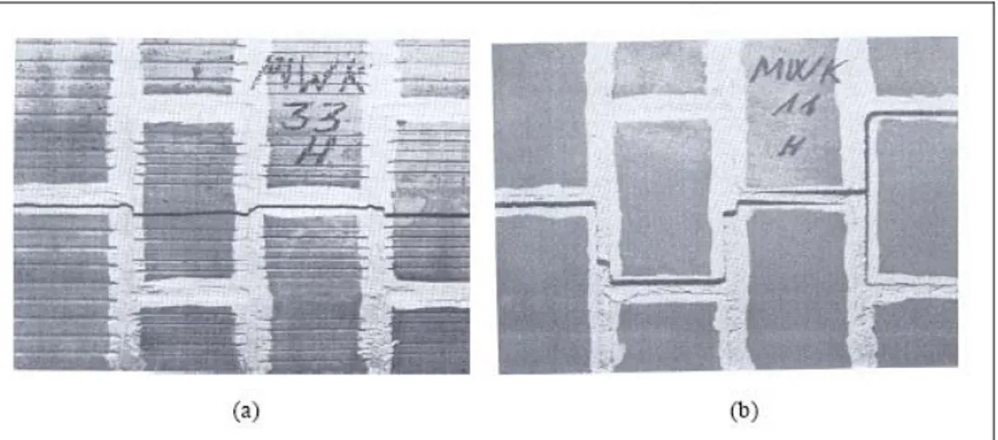
For tensile loading parallel to the bed joints a complete test program was set-up by Backes (1985). The author tested masonry wallets under direct tension and he found that tension failure was affected by the type of the mortar and the masonry units. For stronger mortar and weaker masonry units, the tension cracks passed along the head mortar joints and through the centre of the bricks at the intervening courses, as shown in Figure 1.17a. For weaker mortar joints and stronger masonry units, the tension crack passed along the head joints of the masonry units and the length of bed joints between staggered head joints, as shown in Figure 1.17b.
Introduction 19
Figure 1.17 Modes of tension failure of masonry walls under direct tension, from Backes
(1985): through type (a), zigzag type (b).
Figure 1.18 shows different modes of failure observed by Page (1983) on solid clay units masonry walls subjected to uniaxial tension. As can be seen, for intermediate inclinations of the bed joints, the failure is concentrated on joints.
Figure 1.18 Modes of failure of solid clay units masonry under uniaxial tension, from
Page (1983).
The constitutive behaviour of masonry under biaxial states of stress cannot be completely described from the constitutive behaviour under uniaxial loading conditions. The biaxial strength envelope cannot be described solely in terms of principal stresses, because masonry is an anisotropic material. Therefore, the
Chapter 1 20
biaxial strength envelope of masonry must be either described in terms of the full stress vector in a fixed set of material axes or, in terms of principal stresses and the rotation angle θ between the principal stresses and the material axes. The most complete set of experimental data of masonry subjected to proportional biaxial loading was provided by Page (1981, 1983), see Figure 1.19. The tests were carried out with half scale solid clay units. Both the orientation of the principal stresses with regard to the material axes and the principal stress ratio considerably influence the failure mode and strength.
Introduction 21
The influence of the lateral tensile stress in the tensile strength is not known because no experimental results are available. A lateral compressive stress decreases the tensile strength. The minimum value is achieved when tension direction is perpendicular to the bed joints. In tension-compression (Page, 1983), the failure occurs either by cracking and sliding of the joints or in a combined mechanism involving both units and joints, see Figure 1.20.
Figure 1.20 Modes of failure of solid clay units masonry under biaxial
tension-compression, from Page (1983).
In biaxial compression failure typically occurs by splitting of the specimen at mid-thickness, in a plane parallel to its free surface, regardless of the orientation of the principal stresses, see Figure 1.21. The orientation plays a significant role when the compression in one direction is much greater than the perpendicular one. In this case, failure occurs in a combined mechanism involving both joint failure and lateral splitting. The increase of compressive strength under biaxial compression can be explained by friction in the joints and internal friction in the units and mortar.
It is further noted that the strength envelope shown in Figure 1.19 is of limited applicability for other types of masonry. Different strength envelopes and different failure modes are likely to be found for different materials, unit shapes and geometry. Comprehensive programs to characterize the biaxial strength of different masonry types were carried using full scale specimens, see Ganz and Thürlimann (1982) for hollow clay units masonry, Guggisberg and Thürlimann (1987) for clay
Chapter 1 22
and calcium-silicate units masonry and Lurati et al. (1990) for concrete units masonry.
Figure 1.21 Mode of failure of solid clay units masonry under biaxial
compression-compression, from Page (1981).
Concerning the shear capacity of masonry, we observe that the determination of the shear response of masonry joints is a complex task, since it depends on the ability of the test set-up to generate a uniform state of stress in the joints. Different test configurations are possible and the reader is referred to van der Pluijm (1983, 1998), Hofmann and Stockl (1986) and Atkinson et al. (1989). Obviously, the shear strength increases with the confining compression stress, because of the frictional behaviour of masonry in shear. Moreover, the real behaviour of a joint is generally non-associative, i.e. δn ≠ δt tanφ , where δn and δt are respectively the normal (dilatant) and tangential relative displacements between sliding surfaces at a masonry joint, and φ is the angle of friction. Whilst in practice some dilatancy will be likely to occur when two rough blocks pass over each other, experimental evidence indicates that real joint behaviour is quite complex, with the amount of
Introduction 23
dilatancy being dependent on the micro-scale geometrical and mechanical features of the masonry joint (van Zijl, 2004). Also, it is found that the angle of dilatant friction tends to reduce both with increasing relative tangential displacement and also under the action of increasing normal stresses, see Figure 1.22.
Figure 1.22 Masonry joint behaviour: associative, Coulomb friction (non-associative)
idealisations and typical real behaviours.
A salient feature of masonry is the softening behaviour, which is typical of quasi-brittle materials. Softening is a gradual decrease of mechanical resistance under a continuous increase of deformation and it is due to a process of progressive internal crack growth. Such mechanical behaviour is commonly attributed to the heterogeneity of the material, due to the presence of different phases and material defects, like flaws and voids. Even prior to loading, mortar contains microcracks due to the shrinkage during curing and the presence of the aggregate. The clay brick contains inclusions and microcracks due to the shrinkage during the burning process. The initial stresses and cracks as well as variations of internal stiffness and strength cause progressive crack growth when the material is subjected to progressive deformation. Initially, the microcracks are stable which means that
Chapter 1 24
they grow only when the load is increased. Around peak load an acceleration of crack formation takes place and the formation of macrocracks starts. The macrocracks are unstable, which means that the load has to decrease to avoid an uncontrolled growth. In a deformation controlled test the macrocrack growth results in softening and localization of cracking in a small zone while the rest of the specimen unloads. Figure 1.23 shows characteristic stress-displacement diagrams for quasi-brittle materials in uniaxial tension, uniaxial compression and pure shear.
Figure 1.23 Typical behaviour of quasi-brittle materials and definition of fracture energy:
uniaxial tensile loading (a); uniaxial compressive loading (b); pure shear (c). The integral of the σ−δ diagram is the fracture energy , denoted by Gf and Gc, for tension and compression, respectively. In case of mode II failure mechanism, i.e. slip of the unit-mortar interface under shear loading, the inelastic behaviour in shear can be described by the mode II fracture energy GII,f , defined by the integral
Introduction 25
of the τ−δ diagram. Figure 1.23c shows brittle behaviours in shear. The value of the fracture energy depends on the level of the confining stress.
Shear failure is a salient feature of masonry behaviour which must be incorporated in a micro-modelling strategy. However, for continuum macro-models, this failure cannot be directly included because the unit and mortar geometries are not discretized. Shear failure is then associated with tension and compression modes in a principal stress space.
1.3 Aim and Objectives of the Thesis
The main aim of this thesis is to provide a non linear model, based on the Continuum Damage Mechanics, devoted to the finite element analysis of masonry structures. The work consists in developing a robust and accurate numerical tool for the analysis even of large and complex constructions.
The study focuses on two-dimensional structures, which can be approximated as being in a state of plane stress, such as panels, shear walls and arched structures. The material is studied at the macro-level, i.e. it is modelled as a homogeneous orthotropic continuum without making any distinction between units and joints. This aim will be achieved through the following enabling objectives:
• To gather information on the existing knowledge about Continuum Damage Mechanics models, through a comprehensive literature review. • To develop an efficient model capable of predicting the behaviour of
masonry structures, which includes orthotropic elastic as well as orthotropic inelastic behaviour and incorporates the knowledge of concepts used in crack propagation problems.
• To validate the model by comparing the predicted behaviour with the behaviour observed in experiments on different types of masonry. The
Chapter 1 26
developed model should be able to predict the failure mode and the ultimate load with reasonable agreement with the experimental evidence. • To apply the validated model to engineering practice case-studies.
It is further noted that the model developed and the discussion carried out in this study has a much broader applicability than masonry structures. In fact, the proposed model could be utilized for most anisotropic materials such as plastics, wood and fibre-reinforced composite materials.
1.4 Outline of the Thesis
This thesis consists of six Chapters.
Chapter 1 provides an introduction and states the aim and objectives of the research. A brief overview on the mechanical behaviour of the material and computational modelling of masonry structures is also included.
Chapter 2 reports a review of several Continuum Damage Mechanics models. The aspects related to their numerical implementation are also discussed.
Chapter 3 presents the formulation of a scalar damage model for orthotropic materials. An original methodology is presented, which is a generalization of the classical theories and allows one to use the models and algorithms developed for isotropic materials. Such a methodology is based on establishing a one-to-one mapping relationship between the behaviour of an anisotropic real material and that of an isotropic fictitious one. Therefore, the problem is solved in the isotropic fictitious space and the results are transported to the real field. Orthotropic elastic and inelastic behaviours of the material are taken into account, in such a way that totally different responses can be predicted along the material axes. The proposed tool is able to reproduce the mechanical degradation of the material and to predict the potential collapse under given load conditions.
Introduction 27
Chapter 4 presents the formulation of a two-parameters damage model for masonry. Such a model is more sophisticated than the one described in the previous chapter. In fact, it accounts for different orthotropic behaviours in tension and compression. Individual damage criteria are considered for tension and compression, according to different failure mechanisms. The former is associated with cracking phenomenon, while the latter is associated with the crushing of the material. Totally different elastic and inelastic behaviours can be predicted along the material axes, both in tension and compression. The resulting formulation is easily implemented in a non linear finite element code. Validation of the model is performed by means of a comparison between the calculated numerical results and the experimental results available in the literature for different types of orthotropic masonry.
Chapter 5 validates the damage model developed in Chapter 4 by means of the FE analysis of an engineering practice case study, i.e. a shear wall with openings. A localized-cracks approach is considered instead of the traditional smeared one, in order to obtain more accurate and mesh-objective results. The description of the adopted local crack-tracking algorithm is also provided.
Chapter 6 presents an extended summary, the main contributions and the final conclusions which can be derived from this study. Suggestions for future work are also pointed out.
Chapter 1 28
Chapter 2.
Overview of Continuum Damage
Mechanics and Damage Models
The mechanical behaviour of many materials is complex and highly nonlinear, even for moderate stress levels. The available literature on material modelling includes models based on the theories of Hypoelasticity, Hyperelasticity, Plasticity, Fracture Mechanics, Plastic-Fracture or Continuum Damage Mechanics.
Continuum Damage Mechanics provides a powerful and general framework for the
derivation of consistent material models suitable for many engineering fields. This theory was firstly introduced by Kachanov (1958) in the context of creep related problems. It has been accepted afterwards as a valid tool to deal with complex material behaviour. Continuum Damage Mechanics covers a broad range of applications nowadays. It is used for materials so different as metals, ceramics, rock, concrete and masonry. Such a large acceptance is due to several important factors, namely:
Chapter 2 30
• The simplicity of the approach, which is totally based on Continuum Mechanics Theory. This is a major difference with Fracture Mechanics and leads to a much simpler formulation and interpretation. The damaged material is assumed to remain a continuum and the collective effect of cracks is modelled by modifying the mechanical properties, i.e. stiffness and strength. One or more, scalar or tensorial, field quantities are introduced into the constitutive equations as measures of the degradation of the material.
• The consistency of the theory, which is formulated in a rigorous framework, i.e. the Thermodynamics of irreversible processes.
• The versatility of the approach, which can deal with a large number of problems, e.g. creep, fatigue, brittle or ductile failure, etc.
• The compatibility with other theories. For instance, the combination of Damage Mechanics Theory with Plasticity is straightforward. In addition, it is possible to include thermal and rate dependent effects in the formulation.
This Chapter presents some approaches to this branch of Continuum Mechanics. Basic concepts are defined, together with the theoretical formulation. Then, a comparative discussion concerning some damage models is carried out, in order to emphasize the implications arising from the different backgrounds. In particular, the attention is paid mainly to the models in which the damage is described by one or two scalar variables. A large number of studies deals with such approaches to characterize the mechanical behaviour of materials. The principal features of these approaches will be pointed out, in order to better understand the models that will be formulated in the following Chapters of the thesis.
Overview of Continuum Damage Mechanics and Damage Models 31
2.1 Continuum Damage Mechanics: Background and
Basics
All real materials deform when loaded. The deformation may be elastic or inelastic. It may be time independent or dependent. Occasionally rupture may occur, being either ductile or brittle. The deformational properties are described by constitutive equations, which are either derived from micromechanical or statistical considerations or even postulated to fit measurements test specimens.
In general, constitutive equations relate to the material modelled as a continuum. The deformation is described by a field variable, the strain. The distribution of internal forces in the material is described by another field variable, the stress. These concepts are useful in analyzing the behaviour of load carrying structures in spite of the fact that they do not account for the discrete structure of real materials. Under certain load conditions the material structure may begin to disintegrate. Small cracks may form, voids and other forms of small cavities may appear in highly stressed parts. Such deterioration weakens the material and lowers its load carrying capacity. Because of their nature, these defects are discrete entities. An accurate analysis of their influence would have to consider them as discrete disturbances of the material continuum. This is definitely a prohibitive task.
In a pioneering paper Kachanov (1958) proposed to describe the collective effect of such deterioration by means of a field variable termed continuity. Therefore, an inherently discrete process was modelled by a continuous variable. What was lost in accuracy in modelling the deterioration was then gained in computational simplicity.
The state of the material with regard to deterioration was characterized by a dimensionless scalar field variable
ψ
denoted continuity. To a completely defect free material was ascribed the conditionψ
=
1
, whereasψ
=
0
was defined to characterize a completely destroyed material with no remaining load carryingChapter 2 32
capacity. Kachanov also postulated a law according to which
ψ
changes with time in a material subjected to stress at elevated temperature during extended times. For further details on Kachanov’s analysis of brittle creep rupture the reader is referred to Kachanov (1958, 1986).The continuity Ψ quantifies the absence of the material deterioration. The complementary quantity
D
= −
1
ψ
is therefore a measure of the state of deterioration or damage (Odqvist and Hult, 1962; Rabotnov, 1963). For a completely undamaged material D=0 whereasD
=
1
corresponds to a state of complete loss of integrity of the material structure. The designationD
as fieldvariable to describe the degree of material damage has lately come into a widespread use and will be used in the sequel of the work.
Although Kachanov assumed Ψ to be a scalar field variable, later developments have led to the study of tensorial quantities to describe damage, see Krajcinovic and Lemaitre (1987) and the references therein.
Even though the Kachanov model was entirely phenomenological, micromechanical studies lent support to this model, see Jansson and Stigh (1985). Such results led to increasing interest in damage analyses based on Mechanics principles.
The term Continuum Damage Mechanics was coined by Janson and Hult (1977). The aim of such a theory is to develop methods for the prediction of the load carrying capacity of structures subjected to material damage evolution. It is a counterpart of Fracture Mechanics, which deals with structures containing one or several cracks of finite size. In this latter approach, the cracks are usually assumed to be embedded in a non-deteriorating material. However, Fracture Mechanics and Continuum Damage Mechanics may be combined to predict the damage growth and the resulting decrease of load carrying capacity (Janson and Hult, 1977; Krajcinovic, 1985).
Overview of Continuum Damage Mechanics and Damage Models 33
2.1.1 Damage Variable
Damage in solid materials is the creation and growth of microvoids or microcracks, which are discontinuities in a medium considered as continuous at a larger scale. In engineering, the mechanics of continuous media introduces a Representative Volume Element (RVE) on which all properties are described by homogenized variables. To give an order of magnitude, its size can vary from about 0.1 mm3 for metals and ceramics to about 100 mm3 for concrete. The damage discontinuities are small with respect to the size of the RVE but of course large compared to the atomic spacing, see Figure 2.1.
Figure 2.1 Examples of damage in a metal (microcavities in copper), in a composite
(microcracks in carbon-fiber/epoxy resin laminate), and in concrete (crack pattern). From Lemaitre and Desmorat (2005).
From a physical point of view, damage is always related to plastic or irreversible strains and more generally to a strain dissipation either on the mesoscale, the scale of the RVE, or on the microscale, the scale of the discontinuities.
In the first case (mesolevel), the damage is called ductile damage if it is nucleation and growth of cavities in a mesofield of plastic strains under static loadings; it is
Chapter 2 34
called creep damage when it occurs at elevated temperature and is represented by intergranular decohesions in metals; it is called low cycle fatigue damage when it occurs under repeated high level loadings, inducing mesoplasticity.
In the second case (microlevel), it is called brittle failure, or quasi-brittle damage, when the loading is monotonic; it is called high cycle fatigue damage when the loading is a large number of repeated cycles. Ceramics, concrete, and metals under repeated loads at low level below the yield stress are subjected to quasi-brittle damage.
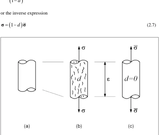
Consider a damaged solid in which a characteristic element of finite volume has been isolated, i.e. the RVE, see Figure 2.2.
Figure 2.2 Damaged element and interpretation of the damage variable.
Let
δ
S be the area of the section of the volume element identified by its normalnG. On this section, cracks and cavities which constitute the damage leave traces of different forms. Let
δ
S
be the effective area of resistance(
δ
S
<
δ
S
)
takingOverview of Continuum Damage Mechanics and Damage Models 35
account of the area of these traces, stress concentrations in the neighbourhood of geometric discontinuities and the interactions between the neighbouring defects. Let
δ
S
D be the differenceD
S
S
S
δ
=
δ
−
δ
(2.1)i.e. the total area of the defect traces corrected for stress concentrations and interactions. We will see in Section 2.1.2 that the concept of effective stress associated with the hypothesis of strain-equivalence enables us to avoid the calculations of
δ
S
D. In fact, it would be extremely difficult to do because of the lack of knowledge of the precise geometry of the defects and because of the doubts regarding the applicability of Continuum Mechanics on this scale.By definition (Lemaitre and Chaboche, 1985), the damage variable is physically defined by the surface density of microcracks and intersections of microvoids lying on a plane cutting the RVE of cross section
δ
S (Fig. 2.2):( )
S
DD n
S
δ
δ
=
G
(2.2) Expression (2.2) provides the mechanical measure of local damage relative to thedirection nG. It is evident that:
• D n
( )
G =0 corresponds to the undamaged or virgin state;• D n
( )
G =1 corresponds to the totally damaged material, hence breaking of the RVE into two parts;• 0≤D n
( )
G ≤1 characterizes the damaged state.If the damage is isotropic, it consists of cracks and cavities with an orientation distributed uniformly in all directions. In this case, the variable D n