self-assembled metal-phthalocyanine on
intercalated graphene
Candidate: Giulia Avvisati, 1401628
Thesis Advisor: Prof. Maria Grazia Betti
PhD School in Astronomical, Chemical, Physical and Mathematical Sciences “Vito Volterra”
PhD in Physics – XXXI cycle January 2019
A Thesis presented for the degree of
Doctor of Philosophy
metal-phthalocyanine on intercalated graphene
Giulia Avvisati
Submitted for the degree of Doctor of Philosophy January 2019
Abstract
We report on advanced organic spin-interface architectures constituted by metal (man-ganese, iron, copper) phthalocyanine molecules magnetically coupled with ferromagnetic layer(s), mediated by graphene. The rippled moir´e superstructure of graphene/Ir(111), intercalated with a single magnetic layer, drives the assembly of evenly-spaced molecu-lar bits, providing preferential adsorption regions for the phthalocyanine molecules. Our X-ray absorption and photoemission results show that the graphene layer shields the elec-tronic/magnetic state of the molecules, screening the charge transfer/orbital intermixing with the metallic surface. The magnetic response of the molecular spin interfaces and its robustness against thermal fluctuations were investigated by X-ray magnetic circular dichroism. Mn-, Fe- and Cu-phthalocyanines assemble on graphene/Co with identical structural configurations, but MnPc and FePc are strongly antiferromagnetically coupled with Co up to room temperature, while CuPc couples ferromagnetically with weaker ther-mal stability. The robust antiferromagnetic alignment is stabilized by a superexchange in-teraction, driven by the out-of-plane molecular orbitals responsible of the magnetic ground state and electronically decoupled from the underlying metal via the graphene layer, as confirmed by ab initio theoretical predictions. The strength and stability of the magnetic coupling is further optimized by the open 3d shell of the central Mn ion. These archetypal spin interfaces can be prototypes to demonstrate how antiferromagnetic/ ferromagnetic coupling can be optimized by selecting the molecular orbital symmetry, paradigmatic ex-amples to exploit in surface-supported molecular spin electronics.
Copyright © 2018 by Giulia Avvisati.
“The copyright of this thesis rests with the author. Information derived from it should be acknowledged”.
Abstract ii
1 Molecular spin interfaces: a brief introduction 1
2 The graphene/ferromagnet substrate: a strategic support 7
2.1 The versatile Co-intercalated graphene/Ir(111) substrate . . . 8
2.1.1 Structural and electronic environment: a template for molecular assembly . . . 8
2.1.2 The magnetic configuration . . . 14
2.2 Simultaneous FeCo intercalation at the graphene/Ir(111) interface . . . 17
2.3 Conclusions . . . 28
3 Molecular architectures on Co-intercalated Gr/Ir(111) 29 3.1 Moir´e-driven molecular self assembly . . . 30
3.2 TMPc-Co interaction mediated by highly corrugated graphene . . . 38
3.2.1 The role of graphene corrugation . . . 46
3.3 Conclusions . . . 52
4 Graphene-mediated magnetic coupling 53 4.1 Super-exchange pathways . . . 54
4.1.1 FePc/Gr/Co: a 180° super-exchange interaction . . . 54
4.1.2 CuPc/Gr/Co: a 90° super-exchange interaction . . . 62
4.2 MnPc/Gr/Co: can we optimize the spin interface? . . . 65
4.3 Robustness against thermal fluctuations of the magnetic response . . . 68
4.4 Conclusions . . . 72
4.5 Perspectives: Optimization of the substrate magnetic state . . . 74
4.6 Perspectives: Tuning the magnetic coupling via electron injection . . . 76 iv
5 Conclusions 81
Appendix 85
A Experimental Techniques 85
A.1 Sample preparation . . . 85
A.2 Interaction of radiation with matter . . . 86
A.2.1 Photoemission Spectroscopy . . . 88
A.2.2 NEXAFS . . . 91
A.2.3 XMCD . . . 93
A.3 Low Energy Electron Diffraction . . . 96
B Experimental Apparatus 98 B.1 The LoTUS laboratory . . . 98
B.2 The SuperESCA beamline . . . 98
B.3 The BOREAS beamline . . . 100
Ringraziamenti 102
List of Figures 103
List of Tables 112
Acronyms 113
Molecular spin interfaces: a brief
introduction
The ultimate goal of nanomagnetism is to establish a route to achieve a well ordered spin network, with the smallest unit, exhibiting a high magnetic anisotropy and tunable magnetic state, robust against thermal fluctuations. This intriguing research field is mo-tivated by the rising of spintronics, i.e., electronics with spins, born with the discovery of the giant magnetoresistance that led to the award of the 2007 Nobel prize to A. Fert and P. Gr¨unberg [1]. From a technological point of view, adding the spin degree of freedom will add substantially more capability and performance to electronic devices. Non-volatile information storage, increased processing speed, decreased power consumption and in-creased integration densities complete the picture [2], inspiring much experimental effort towards magnetic nanostructures. Such systems, besides meeting the demands for devices miniaturization, provide a new platform for fundamental science. Indeed, when dimen-sion/coordination is reduced, exotic (absent/irrelevant in bulk materials) magnetic phe-nomena arise [3, 4], such as increase of the orbital magnetic moment [5], Kondo effect [6], enhanced magnetic anisotropy [5] and many more.
The smallest spin unit is undoubtedly represented by individual atoms, but it is difficult to attain a well-ordered arrangement of single atoms on surfaces [7] as they tend to form clusters, not to mention the effects of thermal-induced mobility [8]. Furthermore, the magnetic state of single-atom magnets strongly depends on the surrounding environment [9] and is very fragile against thermal fluctuations. In particular, single Ho atoms deposited on metallic substrates (e.g. Pt(111)) exhibit perfect paramagnetic behaviour down to 2.5 K [10], while adsorption on the insulating MgO support guarantees the protection of the
magnetic state against scattering with electrons and phonons, ensuring a stable magnetic state up to 35 K, the best configuration achieved and recently reported in Refs. [11, 12]. It is worth to highlight that the Ho adatoms on the MgO/Ag(100) substrate start to migrate on the surface above 50 K, giving an upper limit to the critical temperature of the system. A stable and reproducible long-range ordering of single-ion magnets can be achieved by self-assembly of metal-organic molecules, thanks to their capability to form intermolec-ular weak directional bonds [13], as well as to be sensitive to polarization effects induced by adsorption on metallic surfaces [14]. The final pattern is determined by a subtle in-terplay between molecule-molecule and molecule-substrate interaction [15] and, generally, the spacing between spin units is larger for metal-organic building blocks as compared to inorganic materials, hence preventing undesirable electronic/magnetic coupling among ad-jacent units. The choice of molecular spin units resides in the combined role of delocalized organic π orbitals, driving the formation of well ordered surface-supported architectures with the aforementioned qualities, while the incorporated metallic cores arrange in a reg-ular network with intriguing magnetic/electronic properties [16]. Furthermore, the light weight (low Z) of metal-organic molecules ensures low spin-orbit coupling and hyperfine interactions, and hence long spin lifetimes and diffusion lengths [17]. From a technological point of view, the possibility to combine efficient spin transport with the potential of or-ganic molecular semiconductors could enable molecular spintronics applications, with the ultimate bit being a single molecule [1].
However, molecular spin units often exhibit paramagnetic behaviour at temperatures above a few K [18, 19]. To the best of our knowledge, the most stable configuration achieved so far for surface-supported single-ion molecular magnets, described in Ref. [20], is represented by double-decker phthalocyanines hosting a rare earth atom, specifically terbium, adsorbed on the insulating MgO surface. TbPc2 on MgO exhibit an
excep-tional zero-field magnetic remanence and an unprecedented blocking temperature of 8 K, still far from the goal of room-temperature activity. The desired thermal stability of the molecular magnetic state must then be induced by coupling with a ferromagnetic substrate. Recently, much attention has been paid to the interface between adsorbed molecules and the supporting surface. Several mechanisms occurring at the interface can influence the molecule-substrate interaction [14, 21], such as charge transfer, formation of interface dipoles, hybridization-induced reduction of the molecular symmetry as well as the appearance of the interface-localized electronic states. Direct adsorption of molecules
on the surface of reactive magnetic metals is usually characterised by chemisorption with covalent bonding between the transition metal surface and the adsorbed metal-organic molecule. This results in the strong hybridization between the d bands of the metal and the π molecular orbitals, giving rise to bonding and antibonding hybrid states [22]. Even if the formation of spin-polarized hybrid interface states has interesting spin-filtering proper-ties [22–25], bond formation has the disadvantage to also maximise the charge transfer from the substrate to the molecular orbitals, reducing or even quenching the magnetic moment of the molecular building block [26], as reported in the left part of Fig. 1.1. Explic-itly, E. Annese and her collaborators recently investigated the interface magnetic coupling between adsorbed Iron-Phthalocyanine (FePc) molecules and the underlying Co(0001) sur-face [27]. On the one hand, they successfully obtained a remarkable exchange coupling, much stronger than thermal fluctuations up to Room Temperature (RT). On the other hand, they estimated a reduction by a factor two(ten) of the spin(orbital) magnetic mo-ment, with respect to the molecular crystal, because of re-hybridization and alteration of the spin-polarized molecular orbitals of the FePc molecules in contact with Co.
To achieve the optimized configuration, the magnetic state of the molecular spin units has to be protected by screening the electronic interaction with the metallic substrate, but stabilized against thermal fluctuations via magnetic coupling with the underlying ferromagnet.
In this thesis, we propose a strategic route to design molecular spin architectures that can guarantee (i) a long-range ordering of well-separated spin units (ii) with pre-served electronic/magnetic configuration upon adsorption and (iii) exhibiting a magnetic response robust against thermal fluctuations, up to RT. Such molecular spin interfaces are obtained by depositing our molecular units on Graphene (Gr) intercalated with Co layer(s), combining the decoupling effect of a Gr buffer layer with the magnetic stability induced by coupling with a ferromagnetic substrate.
We choose archetypal molecular spin units: Transition Metal Phthalocyanine (TMPc) molecules. TMPcs are small (1.5 nm wide), square-shaped and planar metal-organic molecules with applications in optoelectronic [28] and in the pigment industry [29], as well as in organic spintronics [30]. They are ideal for in-situ investigation in an ultra-high-vacuum environment, because of their excellent stability that allows for in-vacuo thermal sublimation. TMPcs share an identical Pc cage made up by four benzene and four pyrrole rings, embedding a central metal core. The common configuration of the
organic ligands ensures ordered self-assembly, with reproducible patterns only slightly de-pending on the TM atom [31], while their planar geometry allows the interaction between the extended surface states of the substrate and the central metal ion. Furthermore, the possibility to change the transition metal centres allows exploring different configurations of the molecular spin units, e.g. magnetic moments, easy magnetization direction, mag-netic anisotropy energy... [32]. TMPc molecules offer an excellent playground, allowing to study coupling with magnetic materials [33], intramolecular spin transport [34], Kondo effects [35], and much more intriguing physics.
Metal-organic spin networks can be stabilized by suitable templates, able to preserve their electronic/magnetic state and favouring the desired magnetic response. Gr can be elected as a promising candidate thanks to its excellent properties for spin electronic ap-plications, with high in-plane charge carrier mobility [36] as well as spin filtering [37] and transport [38]. Furthermore, it only weakly couples with adsorbed/underlying materi-als via van der Wamateri-als-like interactions [39, 40], acting as an ideal spacer between metal-organic adsorbates and underlying reactive magnetic surfaces. Magnetic exchange coupling with the Ni(111) surface through Gr has been reported for isolated Co atoms/clusters [41], cobaltocene [42], Co-porphyrin [43] and -octaethylporphyrin [44], as well as for Fe-porphyrin [45] and -phthalocyanine [46]. Notably, C. F. Hermanns and co-workers recently reported a solid magnetic coupling between Co-porphyrins (CoOEP) and (111)-oriented Ni films, through a Gr spacer [44]. The authors provide evidences, also summarized in the right panel of Fig. 1.1, for electronic decoupling of the adsorbed metal-organic molecules thanks to the Gr covering of the Ni surface. The electronic structure and, accordingly, the molecular magnetic moment fully resemble that of a thick CoOEP film, while an an-tiferromagnetic alignment is reported, activated by the presence of the paramagnetic Gr layer. However, RT remanence is still elusive in such Gr-based atomic/molecular systems. A special effort is needed to obtain molecular spin networks with magnetic activity robust against thermal fluctuations, as a first crucial step towards the integration of molecular magnetic bits in operational spintronic devices.
In this scientific context, briefly summarized in Fig. 1.1, we would take the next step and propose novel molecular spin architectures with preserved molecular structural, elec-tronic and magnetic configurations but with magnetic activity robust against thermal fluctuations. The aims of this thesis are:
Figure 1.1: Comparison between the structural [22, 44], electronic [22, 44] and magnetic [27, 44] configurations of molecular spin interfaces with (right) and without (left) the insertion of a graphene spacer.
2. to control the charge transfer/orbital intermixing at the interface between the molec-ular units and the Gr-based support, to prevent filling of the spin-polarized molecmolec-ular orbitals and, accordingly, reduction/quenching of the molecular spin moment; 3. to ensure thermal stability of the magnetic state and to optimize the magnetic
cou-pling channels and determine the fundamental parameters involved in driving the sign and the strength of the coupling.
The very low concentration of metal centers on the TMPc-covered Gr surface demands for surface sensitive experimental techniques, with high photon flux to minimize measure-ments time and avoid sample contamination. Therefore, we exploited X-ray Photoemission Spectroscopy (XPS) and Near Edge X-ray Absorption Fine Structure (NEXAFS) to ad-dress the effect of adsorption on Gr on the core levels and on the frontier empty molecular orbitals, respectively, disentangling the effects on the organic ligands from the interaction channels involving the metal centers. The magnetic activity of the surface was investi-gated by means of X-ray Magnetic Circular Dichroism (XMCD) measurements, allowing for a quantitative determination of the element specific spin and orbital contribution to the magnetic moment, separating the role of the magnetic intercalant from that of the molecular centers.
The ultimate understanding of the fundamental forces driving the self-assembly (Chap. 3) and the magnetic coupling (Chap. 4) at the molecule-graphene/ ferromagnet interface (Chap.2), is indeed crucial to design a molecular magnetic system with the desired func-tionalities.
The graphene/ferromagnet
substrate: a strategic support
The magnetic substrate is the first ingredient to optimize the magnetic coupling in molec-ular spin architectures. Indeed, the choice of the substrate not only influences the sign and the strength of the magnetic coupling, but can also drive the self-assembly of the molecular units and impact on the magnetic state of the adsorbate itself. The ideal sub-strate is capable to (i) electronically decouple the adsorbed molecular units, to preserve their magnetic state upon adsorption, while (ii) allowing for magnetic coupling, essential to stabilize the magnetic state of the system against thermal fluctuations. Finally, (iii) a fine tuning of the relevant parameters for spintronics applications would be desirable. In particular, the magnetic energy must exceed the thermal energy to avoid spontaneous spin flip but, at the same time, must remain below the practical writing energies. Furthermore, a Perpendicular Magnetic Anisotropy (PMA) is preferable to facilitate the writing process as well as inhibit magnetic coupling between adjacent bits. In this chapter, the structural, electronic and magnetic configurations of the ferromagnetic supports for our molecular spin networks are presented. First, we will describe how the moir´e superstructure of pris-tine graphene/Ir is altered upon increasing Co intercalation, to provide a complete picture of the template for our molecular architectures. Then a thorough investigation of the mag-netic properties for this peculiar graphene-based ferromagmag-netic support will be presented and, finally, a route to further optimize its magnetic activity will be proposed.
2.1
The versatile Co-intercalated graphene/Ir(111) substrate
The ideal magnetic support for molecular spin architectures is able to prevent molecular symmetry reduction [47] and the decrease/quenching of the molecule spin moment [26, 27, 48] upon adsorption. Recently, interposing a Gr buffer layer has been proved to effectively decouple the adsorbed TMPc molecules (TM= Fe [39], Co, Cu [49]) from the Gr growth substrate. However, TMPcs preserve their paramagnetic state when not strongly coupled with a magnetic substrate [48].We propose to combine the electronic decoupling role of Gr with the possibility to magnetically couple our TMPc molecular building blocks with a magnetic support by intercalating a ferromagnetic metal beneath the Gr sheet. Intercalation between Gr and its metallic growth substrate is indeed an established route to functionalise Gr from below, as well as to ensure the protection of the intercalant [50–52], without damaging the Gr overlayer. Intercalation is a widely used procedure to decouple the Gr adlayer from its metallic growth substrate [53, 54], to alter its band structure via doping [55, 56] and to manipulate the interaction with the adsorbate from behind [57]. Furthermore, by tuning the Gr/substrate hybridization it is possible to induce/enhance in-plane [58, 59] or out-of-plane [60] magnetic anisotropy of molecular/atomic adsorbates.
Metal intercalation beneath a Gr sheet ensures the growth of a smooth single metal layer, without grain formation, and is an excellent playground to investigate defectless ultrathin films of ferromagnetic metals/alloys with altered properties with respect to their bulk counterpart, and under tensile stress induced by epitaxial growth. In this chapter, this peculiar magnetic support will be described, together with the tuning of its struc-tural arrangement (highly corrugated or flat) and magnetic state (easy-axis or easy-plane anisotropy).
2.1.1 Structural and electronic environment: a template for molecular assembly
Gr can be easily grown on the Ir(111) surface by thermal decomposition of a hydrocarbon precursor, resulting in a high-quality and almost free standing single Gr layer. Because of non-integer mismatch between the lattice parameters of Gr (2.46 ˚A) and Ir(111) (2.72 ˚
A) a 9.32 × 9.32 moir´e superstructure is formed [61, 62], with an average C-Ir distance of about 3.4 ˚A and a gentle corrugation of 0.3 ˚A [63]. The C1s core level of Gr (grey curve in Fig. 2.1), weakly interacting with the Ir(111) surface, consists of one sharp peak
Figure 2.1: Left: Ir4f core level evolution going from pristine Gr/Ir through Co-covered Gr/Ir to Co-intercalated Gr/Ir(111). Center: C1s core level for bare Gr/Ir(111) (grey curve) and upon intercalation of Co. Right: LEED pattern of Gr/Co/Ir(111), with pre-served periodicity and symmetry of the moir´e satellite spots characteristics of pristine Gr/Ir(111). The Co coverage is 1.0±0.1 ML for all the presented measurements.
well approximated by a Doniach-Sunjic profile centered at 284.1 eV and with asymmetry α=0.09 [64]. The weak van der Waals C-Ir interaction is also reflected in the Ir4f7/2
core level (left panel of Fig. 2.1) where the surface component, very sensitive to electronic interaction at the Ir(111) interface, is preserved.
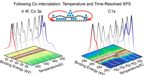
Co intercalation occurs via annealing of a Gr/Ir(111) sample with pre-deposited Co atoms: at first, metallic Co is evaporated onto the Gr/Ir surface kept at room temperature, resulting in an overall reduction of the Ir4f7/2 core level because of Co covering; then the sample is annealed up to 600 K, providing the Co atoms mobility to reach edges, defects and domain boundaries, through which they intercalate below the Gr sheet [65–68]. To shed more light on the intercalation process, we accurately monitored the evolution of the Ir4f (Fig. 2.2, left) and C1s (Fig. 2.2, right) core levels as a function of the annealing temperature, in a time-resolved XPS experiment. As previously mentioned, at RT the Co-covered Gr/Ir(111) sample presents reduced spectral intensity but with almost pre-served lineshape, as reported in Fig. 2.2. At increasing annealing temperature the spectra smoothly evolve, with the reduction of the Ir4f surface component and the depletion of the sharp C1s feature at 284.1 eV. Concurrently, a double-peaked Gr/1 ML Co C1s core level develops, up to 600 K when the pre-deposited Co is fully intercalated. At the end of the process, the interface component of the Ir4f7/2 core level is reduced and will be
fully quenched at the completion of the first intercalated Co layer, without any further alteration of the spectral lineshape, ruling out any surface-alloy formation expected for Co intercalation obtained at higher annealing temperatures [69]. Likewise, the C1s
spec-Figure 2.2: Ir4f (left) and C1s (right) time-resolved XPS, following Co intercalation as a function of the sample annealing temperature.
trum of Gr also evolves upon intercalation of Co: the single C1s component of bare Gr/Ir is quenched and replaced by two features, representing regions with different bonding strengths [66, 70, 71]. When a single Co layer is intercalated at the Gr-Ir(111) interface it arranges pseudomorphically to the Ir(111) surface, thus preserving the periodicity and symmetry of the Gr/Ir(111) moir´e superstructure (as confirmed by the Low-Energy Elec-tron Diffraction (LEED) pattern in Fig. 2.1) while, due to the sElec-tronger C-Co interaction, the corrugation is enhanced by a factor five (from 0.3 ˚A to 1.5 ˚A) [66, 70–73].
To elucidate the origins of the C1s core level of Gr/1 ML Co, theoretical Density Functional Theory (DFT) calculations were performed using the QUANTUM ESPRESSO package in the Local Density Approximation (LDA)1. Starting from a commensurate Gr-Co configuration, several registries, reported in the right part of Fig. 2.3, were considered, inspired by recent measurements on Gr/Co highlighting the presence of two C species depending on the adsorption sites on Co(0001) [70, 75]. However, both the experimental results and the computed core level shifts (left panel of Fig. 2.3) agree that the C-Co registry cannot justify such large separation and the moir´e corrugation must be taken into account to reproduce the C1s core level. At first, since the description of the full moir´e unit cell requires a huge computational effort, the influence of Gr-Co distance and relative registry was investigated within the so-called egg box model, in which the C atoms height
1
Figure 2.3: Top: Core level shift (left) computed for different registries (right) of Gr on Co layer(s) as a function of C-Co distance. Bottom: (left) C atoms height distribu-tion within the moi´e unit cell; simulated (centre) and measured (right) XPS spectrum of Gr/Ir(111) (dark green curves) and Gr/1 ML Co/Ir(111) (light green curves). Figure adapted from Ref. [74].
distribution is given by:
h(~r) = havg+ 2 9∆h[ 3 X i=1 cos(~ki· ~r)] (2.1.1)
with ∆h = hmax− hmin, havg = hmin+ 1/3∆h assuming the values reported in Ref. [72]
(hmax= 3.29 ˚A, hmin= 2.02 ˚A). With this model it was possible to extrapolate the C-Co
distance distribution within the moir´e cell (bottom left in Fig. 2.3) and, by using the core level shifts computed for commensurate Gr/Co at different C-Co distances (top left Fig. 2.3), the two peaks in the XPS spectrum were perfectly reproduced, as reported in the bottom part of Fig. 2.3. This confirms that they arise from the enhanced corrugation of Co-intercalated Gr. In particular, we observed the formation of two nonequivalent adsorption sites, namely valleys and hills, respectively being the regions closer to and further from the intercalated single Co layer. The component at 284.4 eV corresponds to C atoms weakly interacting with the Co-Ir support, hence it is attributed to the hill regions of the highly corrugated moir´e superstructure, while the peak located at 284.9
Figure 2.4: Sketch of the dipole formation for highly corrugated Gr/Ru(0001), as inspired by Ref. [81].
eV is ascribed to highly interacting C atoms placed closer to Co [70, 71]. The different intensity ratio is due to the fact that, even if the corrugation is between 1.2 and 1.8 ˚A, around 70% of Gr C atoms lie closer to the Co layer and, accordingly, the “valley” peak is three times more intense than the “hill” one, and accounts for the 74% of the total area [74]. Notably, these results were later confirmed by theoretical simulations of the full moir´e superstructure, corresponding to 10×10 Gr plus 9×9 unit cells for the single Co layer and the Ir substrate [76].
The different bonding strengths experienced by the C atoms at different distances from the reactive metallic substrate induces a local modulation of the surface potential, with a work function variation of around 200 meV between the top and bridge sites of the moir´e superstructure [77]. The enhanced corrugation, even if associated to only a tensile strain of the order of 1% as recently reported for Gr/Ru(0001) [78], produces a reorganization of the charge density distribution. As a consequence, lateral electric dipoles are formed, as sketched in Fig. 2.4. The strategical role of moir´e patterns in driving the ordered self-assembly of adsorbed atoms [79, 80] and molecules [81, 82] can guarantee the long-range order of molecular spin networks.
At increasing quantity of intercalated Co, the film smoothly recovers the bulk Co (0001) configuration, almost commensurate to the Gr lattice. Intercalation of 6-8 ML Co can be performed step-by-step or all-at-once, giving the same results of high quality samples [51, 70]. In the left panel of Fig. 2.5, the evolution of the LEED pattern at increasing thickness of the intercalated film is reported. The moir´e pattern of Gr/Ir(111) is gradually smeared out and the LEED pattern exhibits a 1×1 hexagonal structure upon completion of the sixth Co intercalated layer, indicating lattice mismatch relaxation and commensurate/flat Gr sheet on the Co thick film [70]. Concurrently, the two components of the C1s core
Figure 2.5: Evolution of the LEED pattern (left) and C1s core level (right) upon subse-quent Co intercalation beneath the Gr sheet.
Figure 2.6: Gr/Co/W(110): (a) C1s core level (hν 400 eV), the structural model (top-hollow) and the LEED (122 eV primary energy) are reported in the inset. (b) k-space image of the C1s full width at half maximum. Figure adapted from Ref. [70].
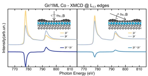
Figure 2.7: XMCD spectra at the L2,3 absorption edges of Co for Gr/1 ML Co acquired
at room temperature and in remanence condition both at normal (left) and grazing (right) incidence. The experimental geometry is sketched in the inset.
level, attributed to the C atoms in the valley or in the hill regions, approach each other and become of comparable intensity, towards the lineshape of Gr/Co(0001). In fact, the two peaks, separated by 270 meV [75], reflect the two equally populated adsorption sites of Gr on Co(0001), depending if a C atom lies on top of a first-layer (top site) or second-layer (hollow site) Co atom. This is confirmed by recent photoemission (Fig. 2.6 left) and photoelectron diffraction (Fig. 2.6 right) measurements of Gr directly grown on a 15 layer film of Co(0001) grown on W(110) [70]. The C1s core level is much broader (700 meV) than the sharp Doniach Sunjic profile of Gr/Ir (250 meV). Furthermore, the k-image of the Gr C1s core level highlights a 120 meV modulation of the peak width across the Gr Brillouin zone. The reported linewidth modulation was attributed to diffraction effects arising from different C sites during the photoemission process, ruling out the existence of one single component. The authors concluded that the two carbon sublattices occupy different adsorption sites in the 1×1 phase, associated to the presence of two main components [70].
2.1.2 The magnetic configuration
The magnetic state of ultrathin magnetic films can be investigated by means of XMCD measurements, that probe the spin imbalance of the empty magnetic states along the direction of the applied magnetic field, collinear with the X-ray beam. In Fig. 2.7 the XMCD spectrum acquired at room temperature and in remanence conditions, i.e., after
Figure 2.8: Field-dependent XMCD measurements at the Co L3 edge, acquired at T= 3
K and normal (dark blue circles) and grazing (light blue squares) incidence for Gr/1 ML Co.
removing the 6 T magnetic field, is presented for the Gr/1 ML Co system both at Normal Incidence (NI) (left) and Grazing Incidence (GI) (right). The spectra consist of two sharp white lines separated by 15 eV, representing the transitions from the Co 2p3/2 (L3
absorption edge at 778 eV) and 2p1/2 (L2 edge at 793 eV) to the empty 3d states. By
comparing the left and right panels of Fig. 2.7 it can be noticed that the remanent XMCD signal is about three times more intense when probed at NI than at GI. This indicates that this sample has a clear out-of-plane magnetic anisotropy, preferring to align the spins perpendicularly to the surface plane, in agreement with recent literature [71, 72, 83]. This picture is confirmed by the hysteresis loops acquired at NI and GI reported in Fig. 2.8. Indeed, Gr coating of Co layer(s) has proved to effectively enhance the PMA of Co ultrathin films, stabilizing it up to 4 Co layers. This was attributed to a fairly strong electronic interaction between the Gr π orbitals and the Co dz2 state [70, 84], shifting them towards
the Fermi level [83, 85]. The strange wasp-waisted shape of the field-dependent XMCD signal, acquired alogn the hard magnetization direction, can pinpoint towards complex magnetic domains contributing to the uni-axial magnetic anisotropy [86, 87], as this is usually attributed to the presence of magnetic domains exhibiting different coercivities [88–90].
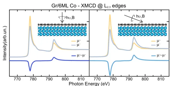
On the other hand, when a thicker Co film is interposed between Gr and Ir(111), the Gr/Co substrate presents an in-plane magnetic anisotropy, resembling that of pristine Co(0001). In Fig. 2.9 we report the XMCD characterization of Gr/6 ML Co/Ir(111),
Figure 2.9: XMCD spectra at the L2,3 absorption edges of Co for Gr/6 ML Co acquired
at room temperature and in remanence condition both at normal (left) and grazing (right) incidence. The experimental geometry is sketched in the inset.
Figure 2.10: Co hysteresis loops, acquired at T= 3 K and normal (dark blue circles) and grazing (light blue squares) incidence for the Gr/6 ML Co sample. In the inset the details of the low-field trend is reported.
as acquired at room temperature and after removing the 6 T magnetic field. In this case a slightly more intense dichroism (50% higher) is observed when the photon beam impinges, and hence the magnetic field is applied, at 70◦with respect to the surface normal. This clearly indicates that the magnetic anisotropy has changed, by only increasing Co coverage, from perpendicular to parallel to the sample surface. When Gr is grown oriented on a Co(0001) substrate, the electronic states of the Gr adlayer strongly hybridize with the extended states of the metallic substrate [91], giving rise to a 100% spin polarized
Figure 2.11: Scanning Tunneling Microscopy image of Gr intercalated with Fe and Co, image from Ref. [98]. The authors explain that, at the used bias voltage, Fe areas appear bright.
interface mini-cone. This state has significant contributions from both Gr π and Co 3d states and makes this substrate very interesting for spin transport applications [92, 93]. The possibility to further play with the magnetic activity of our Gr-based support, aiming at the ultimate optimization of the magnetic response of the adsorbed molecular spin network, will be discussed in the next section.
2.2
Simultaneous FeCo intercalation at the graphene/Ir(111)
interface
The magnetic state of the Gr/ferromagnet substrate is a key ingredient to stabilize/optimize the response of the molecular architecture. It is well known that the ordered equiatomic FeCo alloy presents the highest magnetic moment among the known 3d ferromagnetic materials/alloys, a mandatory requirement for recording media [94]. Furthermore, an in-credibly high Magnetic Anisotropy Energy (MAE) is found when the cubic symmetry is broken [95], for example by epitaxially growing FeCo films on suitable substrates [96]. When forced to arrange in an hexagonal pattern, FexCo1−x monolayers exhibit enhanced
orbital magnetic moment and MAE close to the equiatomic composition, as a result of the change in the Fe and Co dx2−y2 ↓ and dxy ↓ population [97].
Recently, a subsequent evaporation and intercalation of Fe and Co between Gr and Ir(111) has led to the formation of segregated Fe and Co islands, without alloy forma-tion, as reported in Fig. 2.11 from Ref. [98]. In particular, the authors noticed that Co
Figure 2.12: C1s core level (left) and LEED pattern (right) for 0.5 ML FeCo co-intercalated between the Gr sheet and the Ir(111) growth substrate (top). To ease com-parison the XPS and LEED measurements are reported also for Gr/0.8 ML Co (center) and 0.7 ML Fe (bottom).
preferentially decorates Ir step edges, while Fe preferentially nucleates to form islands. We propose a different strategy: co-evaporating, at identical rates, metallic Fe and Co on the Gr/Ir sample kept at 500 K. This optimized procedure, established carefully selecting the substrate temperature and Fe, Co evaporation fluxes, results for the first time in a homogeneous and smooth intercalated FeCo film. Furthermore, intercalation below Gr ensures a better film quality, with respect to that grown by atomic-beam-epitaxy, without kinetically-limited interlayer diffusion usually leading to 3D growth (i.e., cluster/aggregate formation).
First we want to shed light on the early growth stages of the Gr/FeCo/Ir(111) het-erostructure, in order to verify if it is similar to what obtained for Gr/Co. To facilitate comparison we report in Fig. 2.12 the C1s core level for Gr intercalated with 0.5 ML
Fe44Co56 (top), 0.8 ML Co (centre) and 0.7 ML Fe (bottom). In all the three spectra we
notice the co-existence of three features, the peak at 284.1 eV of the pristine Gr/Ir(111) and two new peaks at 284.4 eV and 284.9 eV, attributed to the Gr/FeCo (Fe,Co) sam-ple. The binding energy and the lineshape of the intercalated regions resemble that of Gr intercalated with pure Co(Fe), indicating that the energetics of FeCo-intercalated Gr is similar to that of bare Co(Fe), with the presence of Gr regions undergoing different binding strength (valleys and hills). Furthermore, the energy separation between the valleys and hills contribution to the C1s core level, in very good agreement with what was measured for Gr/Co, suggest a similar moir´e corrugation of 1.5–1.8 ˚A, in agreement with what is reported for Gr/Fe/Ir(111) [99]. The LEED patterns (right panel of Fig. 2.12) coincide with that of the Gr/Ir moir´e superstructure for all the three cases, meaning that, at the early growth stages, the interatomic distance of the FeCo film stretches and adapts to the Ir(111) lattice parameter. We want to emphasize that the only information we have on the FeCo monolayer structure comes from the LEED measurements, hence we can safely claim that the growth is pseudomorphic to the Ir(111) surface, but not exclude the presence of structural dislocation induced by the high deposition temperature [97].
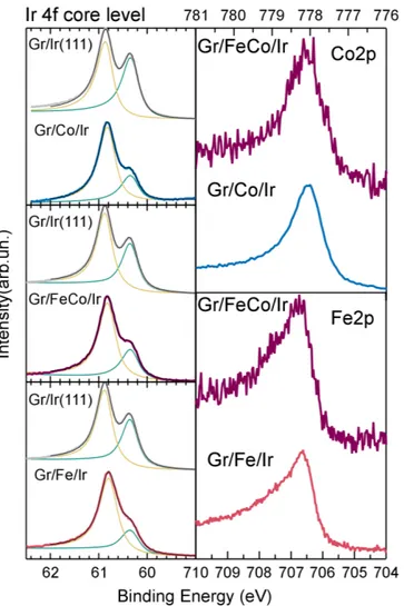
Before turning to the characterization of the magnetic properties of this peculiar sub-strate, we want to further investigate the electronic configuration at the interface with the Ir(111) surface. In the left panel of Fig. 2.13 we present the evolution of the Ir4f core level of the Gr/Ir substrate upon intercalation of Co (top), Fe (bottom) and FeCo (centre). We can notice that they follow the same trend proposed at the beginning of this chapter, with the quenching of the Ir surface state because of the strong metal-iridium interaction. Recently, J. Brede and coworkers [100] revealed that Fe interdiffuses in the Ir substrate, forming a superficial alloy, already at 600–650 K. The Fe-Ir alloying is reflected in a shift of the Ir4f (Fe2p) core level by around 150 meV towards lower(higher) binding energies. In order to avoid alloy formation, we kept the temperature well below 600 K during intercalation and, indeed, no evident shift can be appreciated in the experimental data (Fig. 2.13) for all the intercalated samples. In the right part of the Fig. 2.13 we report the Fe (bottom) and Co (top) 2p core levels, when co-evaporated (purple curve) and separately intercalated (red, Fe, and blue, Co, curves). No considerable alteration of the lineshape at the interface with the Ir(111) surface was observed, confirming that no Fe(Co)-Ir alloy is formed. It is worth noting that the success of the complete intercalation process was further checked by exposing the sample to 10−6 mbar of O2 for 10 minutes
Figure 2.13: Left: Ir4f core level evolution from the bare Gr/Ir (grey curve in each panel) to the Gr intercalated with 0.8 ML Co (top), 0.5 ML FeCo (center) and 0.7 ML Fe (bottom). Right: Comparison between the Co (top) and Fe (bottom) 2p core levels when intercalated separately (blue and red curve, respectively) and at once (purple curve).
Figure 2.14: XMCD measurements at the Fe and Co L2,3 absorption edges of a reference
bulk sample: a FeCo single crystal oriented along the 100 surface. The spectra were acquired at room temperature and in a 0.7 T magnetic field and at GI.
and checking that no sign of oxidation arises neither in the absorption spectra nor in the magnetic dichroism measurements. This not only confirms the complete intercalation, but also the quality of the FeCo intercalated layers.
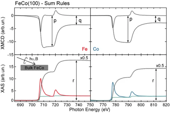
Turning to the magnetic properties of the Gr/FeCo substrate, we first describe, as a reference, the magnetic state of a FeCo single crystal oriented along the (100) surface. The spectra, acquired at room temperature and in a GI experimental geometry, are reported in Fig. 2.14 and consist of two sets of white lines: at 707 eV (L3) and 720 eV (L2) for
transitions from the Fe 2p to the empty 3d states and at 778 eV (L3) and 793 eV (L2) for
transitions located on the Co atoms. The spin and orbital contribution to the magnetic moment can be extracted from the experimental data according to the sum rules for the orbital (L) and effective spin (Sef f) moments, including the D term accounting for spin
anisotropy within the atom [101, 102]:
L = −4 3nh R L3+L2(µ−− µ+)dE R L3+L2µ−+ µ+ = −4 3nh q r (2.2.2) S + 7D = −nh 6RL 3(µ−− µ+)dE − 4 R L3+L2(µ−− µ+)dE R L3+L2(µ−+ µ+)dE = −nh 6p − 4q r (2.2.3)
where p,q and r are highlighted in Fig. 2.15 and nh is the number of 3d holes, assumed
to be 2.4 and 3.4 for Co and Fe, respectively [97]. The sum rules were applied at all the experimental spectra and the results are summarized in Tab.2.2. We also report the ratio L/Sef f to rule out any dependence on the considered number of holes, that can be
altered by electron donation from Fe(Co) to the Gr adlayer and to the Ir support [103], thus favoring comparison with the existing literature.
Figure 2.15: XAS (bottom) and XMCD (top) spectra at the Fe (left) and Co (right) L2,3 absorption edges. Appended to the experimental data we report the XAS arctangent
background (green lines) and the integrated signals (dashed black lines). Co µL Co µS Fe µL Fe µS
bct Fe0.4Co0.6 [104] 0.15 1.73 0.10 2.20
bcc Fe [105] 0.09 1.98
hcp Co [105] 0.15 1.62
bcc FeCo(100) 0.15 1.93 0.20 2.43
Table 2.1: Comparison between the spin and orbital magnetic moments of bct FeCo, pure Fe(Co) and of a single FeCo(100) crystal.
Figure 2.16: XMCD measurements at the L2,3 absorption edges for bcc Fe (left) and
Figure 2.17: XMCD spectra at the L2,3 absorption edges of Fe and Co for Gr/1 ML
FeCo acquired at T= 3 K and in remanence condition both at normal (left) and grazing (right) incidence. The experimental geometry is sketched in the inset.
In Tab.2.1 we report the magnetic moment of our single FeCo crystal, as extrapo-lated by XMCD measurements, and of bcc Fe(hcp Co) from the literature. Notably, an enhancement of the total magnetic moment, from 2.07 µB (1.77 µB) to 2.63 µB (2.08
µB) for Fe(Co) can be observed. The increase in the Fe magnetic moment upon FeCo
alloy formation is generally attributed to a strong hybridization between Fe, a weak fer-romagnet, and Co, a strong ferromagnet with a filled 3d↑ and an empty 3d↓ bands. This
induces a redistribution of the spin-polarized Fe 3d orbitals, from the spin minority to the spin majority band, transforming Fe in a strong ferromagnet [97, 106]. A steep increase in the MAE is also expected upon Fe-Co alloy formation. In particular, for bulk FeCo tetragonally-distorted [95] and epitaxial FeCo island on Pt(111) [107], the effect of Fe was to move the Fermi level down to the point where the spin-split dxy and dx2−y2 bands cross,
maximizing the energy difference between the two magnetization directions.
XMCD measurements were performed for a single FeCo layer intercalated between Gr and Ir(111), both at GI and NI, and are presented in Fig. 2.17. The two sets of white lines are reproduced in this sample, with the same Fe and Co jump-edge ratios, hence confirming the intercalation of a nearly equiatomic alloy, with a slight excess of Co. Being the remanent dichroic signal more intense at NI (left) with respect to the GI (right) ex-periment, we can conclude that the single intercalated layer presents an out-of-plane easy magnetization axis, in agreement with what reported by G. Moulas and co-workers for hexagonally-arranged single FeCo layers, both smooth and granular, grown epitaxially on
Figure 2.18: Element-selective hysteresis loops for the Gr/1 ML FeCo sample acquired at T= 3 K for Fe (red/pink) and Co (blue/light blue) at normal (left) and grazing (right) incidence.
Figure 2.19: LEED pattern for 8 ML FeCo co-intercalated between the Gr sheet and the Ir(111) growth substrate.
Pt(111) [97]. Element-sensitive hysteresis loops acquired for Fe and Co in the two experi-mental geometries (Fig. 2.18 left and right panels) confirm this picture. Furthermore, the Fe and Co hysteresis loops perfectly mimic each other, suggesting a strong ferromagnetic (double)exchange coupling between the two species [106]. This definitely indicates that the two elements do not form independent segregated islands but do magnetically couple, forming a single magnetic unit. It is worth noting that the wasp-waisted character of the hysteresis loops, acquired along the hard magnetization axis (right panel of Fig. 2.18), is enhanced in this configuration, probably pinpointing to more complex magnetic domains in this stretched FeCo arrangement.
Figure 2.20: XMCD spectra at the L2,3 absorption edges of Fe and Co for Gr/8 ML
FeCo acquired at room temperature and in remanence condition both at normal (left) and grazing (right) incidence. The experimental geometry is sketched in the inset.
Figure 2.21: Element-selective hysteresis loops for the Gr/8 ML FeCo sample acquired at T= 3 K for Fe (pink) and Co (light blue) at grazing incidence, i.e., along the easy magnetization axis.
the LEED pattern (Fig. 2.19) exhibits a structural arrangement commensurate with the Gr lattice, in agreement with what already described for Gr/Co. The moir´e rippling is released and a FeCo film is formed almost commensurate with the Gr layer. Furthermore, the magnetic moments of the 8 ML FeCo intercalated alloy prefer to align parallel to the surface plane, indicating a tuning of the out-of/in-plane magnetic anisotropy for different FeCo thickness. In the left panel of Fig. 2.20, the XMCD spectrum, acquired applying a magnetic field of 3 T, highlights the small remanent signal, again probably due to the wasp-waisted hysteresis along the hard magnetization axis, due to the presence of complex magnetic domains (i) antiferromagnetically coupled or (ii) with different coercive fields [88–90]. The element-resolved hysteresis loops of Fe and Co acquired along the easy magnetization direction of the film confirm the coupling of the two magnetic species also at higher coverages.
Finally, we comment on the results of the spin and orbital moments as determined via the sum rules (Eqs. 2.2.2 and 2.2.3) applied to our experimental data. When a single Co layer is intercalated beneath Gr, both Sef f and L are enhanced with respect to their bulk
value [105] because of the concomitant effects of reduced dimensionality and stretched lattice, and are fairly comparable with what is reported for Co islands on Pt(111) [5], Co monolayers on Rh(111) [108] and on Pt(111) [109], and what is theoretically predicted for Gr/Co [72]. When Fe and Co are co-intercalated beneath Gr, we observe an increase of both spin and orbital magnetic moments for Fe, as compared to the bulk values [105]. Furthermore, we remark an increase of a factor two in the L/Sef f ratio with respect
to what is reported in the literature for a single Fe layer intercalated below Gr [103], while the magnetic properties of Co is not strongly affected by the presence of Fe atoms. When a higher quantity of FeCo is intercalated at the Gr/Ir interface, both the spin and the orbital magnetic moments of Fe are strongly enhanced with respect to bare Fe, with slightly reduced values compared to the single FeCo layer. In particular, Sef f(L)
increases from 1.95 µB (0.17 µB) for bare Gr/Fe to 2.86 µB (0.27 µB) for the Gr/FeCo
sample. Notably, the magnetic moments of such (ultra)thin films are further increased with respect to the bulk FeCo sample (see Tab.2.1), because of reduced dimensionality effects as well as structural deformation induced by epitaxial growth on Gr/Ir.
Conclusions 27 Co L Co Sef f Co L/Sef f Fe L Fe Sef f Fe L/Sef f average M bcc FeCo(100) 0.15±0.03 1.93±0.13 0.08±0.02 0.20±0.06 2.43±0.21 0.08±0.03 2.36±0.43 IP Fe 0.17±0.03 1.95±0.17 0.09±0.02 2.12±0.20 IP Co 0.19±0.02 1.94±0.09 0.10±0.02 2.13±0.11 IP FeCo 0.22±0.04 2.13±0.18 0.10±0.03 0.27±0.08 2.86±0.27 0.09±0.04 2.74±0.57 OOP Co 0.26±0.06 1.98±0.11 0.13±0.04 2.24±0.17 OOP Fe [103] 0.049±0.01 OOP FeCo 0.22±0.05 1.98±0.15 0.11±0.03 0.31±0.07 2.59±0.25 0.12±0.03 2.55±0.52
Table 2.2: Spin and orbital contribution to the magnetic moment, expressed in units of µB, of Fe and Co, as estimated via the sum rules,
2.3
Conclusions
In this chapter we have thoroughly described the intercalation of 3d ferromagnetic met-als/alloys beneath Gr, starting from the well-characterized Gr/Co interface and then proposing a viable route to optimize the Gr/ferromagnet magnetic state. In particular, (i) the enhanced corrugation of the Gr/1 ML Co(Fe, FeCo) induces a site-dependent po-larization field, which can drive the self-assembly of the molecular units; (ii) it is possible to switch the easy magnetization direction by only increasing the amount of intercalated ferromagnetic metal/alloy, as deduced by angle-dependent XMCD measurements and (iii) by co-evaporating Fe and Co on a hot Gr/Ir(111) substrate, a magnetically coupled FeCo alloy is formed, exhibiting maximum magnetic moment because of both alloy formation and dimensionality effects. The structural growth of intercalated FeCo resembles that of pure Co(Fe), commensurate to the Ir(111) surface and to the Gr lattice, respectively at the early stages and for high (8 ML) FeCo quantity.
The ferromagnet-intercalated Gr substrate not only drives the self-assembly of the molecular adsorbates, providing a template for well-ordered spin architectures, but is the key enabler of the magnetic aligning. Maximizing the magnetic moment of the molecular support is then fundamental to further stabilize the magnetic state of molecular units against thermal fluctuations, up to device working temperature.
Molecular architectures on
Co-intercalated Gr/Ir(111)
Electronic interactions of adsorbed π conjugated planar molecules with metallic centers at the interface with a metal may induce charge transfer, distortion of the ligand field and re-duction of electron-electron correlations because of hybridization with the metal extended states. Any alteration of the molecule structural/electronic configuration at the interface with the metallic support would affect the magnetic state of the molecular spin network. It is evident that a full understanding of the interaction mechanism, together with the possibility of disentangling the role of the organic ligands from that of the metal center, is of outermost importance to optimize the magnetic response of our graphene-supported TMPc molecular architectures. In this chapter we will investigate the long-range ordering and the adsorption geometry of FePc, Copper-Phthalocyanine (CuPc) and Manganese-Phthalocyanine (MnPc) adsorbed on Gr/Co, to prove that the peculiar Gr/Co substrate provides a suitable template to obtain spin networks with evenly spaced molecular building blocks. We will then study, with a combined X-ray absorption and photoemission spec-troscopy approach, the Gr-mediated electronic interaction channels, separating the role of the common organic ligand and of the metallic centers with different occupation of the d metal states. Finally, we will examine the effects of the Gr corrugation, by monitoring the TMPc-Co interaction when the Gr sheet lies flat and commensurate on Co layers, with an increased C-Co distance.
TMPcs (H16C32N8TM) are square-shaped planar molecules constituted by an organic
cage (Pc) hosting at its centre a transition metal core, usually in a 2+ oxidation state.
The d states, immersed in a D4h ligand field, split according to the irreducible symmetry
representation as b2g (dxy), a1g (dz2), two degenerate eg orbitals (dxz,yx) and the b1g state
(dx2−y2), lying higher in energy [18]. Among all the TMs that can be placed at the centre
of the Pc ring, we chose Mn, Fe and Cu, with different symmetry of the spin-polarized 3d metal states, as reported in Fig. 3.1. Indeed, the S=1 spin magnetic moment of isolated FePc molecules is carried by one of the two degenerate eg orbitals and by the a1g state,
with a dominant out-of-plane character. On the other hand, CuPc has S=1/2 with only one single hole in the purely in-plane b1g orbital, while MnPc, with its open d5 shell and
it S=3/2 spin ground state, presents a mixed character, with two half-filled molecular orbitals protruding out of the molecular plane (eg and a1g) and one unpaired spin in the
b2g state with planar symmetry [18].
In this chapter we will test the Gr-based magnetic template described in Chap.2 in driving the ordered assembly of the TMPc network, as well as in protecting the molecular electronic/magnetic configuration. To enlighten the open interaction channels, we will investigate the role of the different occupancy and symmetry of the molecular orbital carrying the magnetic moment in the Gr-mediated TMPc-Co electronic interaction.
3.1
Moir´
e-driven molecular self assembly
TMPc molecules are known to easily self-assemble in ordered architectures when deposited on suitable template surface. The adopted structural arrangement is mainly determined by their common organic cage, driven by a delicate balance between molecule-molecule and molecule-substrate interaction [111]. In particular, on reactive surfaces, e.g., Co, metal-organic molecules arrange in a random fashion, because of strong chemical interaction with the substrate that suppresses molecular diffusion [112]. On the other hand, on weakly in-teracting patterned surfaces, e.g., Au(110), TMPc deposition induces a 1×n reconstruction of the plastic gold surface to accommodate the molecules in a one-dimensional chain, as de-termined by P. Gargiani and co-workers for FePc, CoPc and CuPc in Ref. [31] and reported in Fig. 3.2. However, this configuration is associated with a reduction (FePc)/quenching (CoPc) of the molecular magnetic moments, since the out-of-plane protruding molecular orbitals get filled by electron injection from the gold surface [48]. In light of this, it is evident that decoupling the adsorbed molecules from the metallic surface is crucial to
pre-in-plane b1g a1g eg b2g FePc S=1 S=1/2 X AS ( arb.un.)
Photon Energy(eV) Photon Energy(eV) Photon Energy(eV) 704 706 708 710 712 714 928 930 932 934 936 636 638 640 642 644 646 648
in-plane
out-of-plane out-of-plane in-planeout-of-plane
Fe L3-edge Cu L3-edge eg eg a1g b1g b1g b1g S=3/2 Mn L3-edge CuPc MnPc b1g a1g eg b2g b1g a1g eg b2g dx2-y2 dz2 dzx,zy dxy dx2-y2 dz2 dzx,zy dxy
Carbon Aza-bridge Nitrogen Pyrrolic Nitrogen
Iron Copper Manganese
Figure 3.1: Electronic ground state configuration of TMPc (TM=Fe, left, Cu, center, Mn, right) molecules. In the upper panel a sketch of the the molecules and of the metal 3d states is presented. In the lower panel the X-ray absorption spectrum at the metal L3
edges for thick TMPc films (TF) is presented, acquired with in-plane (lighter curve) and out-of-plane (darker curve) polarized radiation.
Figure 3.2: STM images of TMPcs (TM= Fe, left, Co, centre, Cu, right) self-assembled in nanochains on the reconstructed Au(110) surface. Image from Ref. [48].
Figure 3.3: STM image (left) and structural model (right) for CoPc molecules adsorbed on pristine Gr/Ir. Figure from Ref. [110].
Figure 3.4: Theoretical simulations optimizing the geometry of the Gr/Co/Ir full moir´e unit cell plus an adsorbed FePc (top) and CuPc (bottom) molecule.
serve the electronic/magnetic state of the molecular units, e.g., by interposing a Gr buffer layer between the adsorbed molecules and the metallic support [39, 58]. When TMPcs are adsorbed on the inert Gr/Ir(111) they weakly interact with the substrate and arrange in a square-shaped pattern, mainly driven by molecule-molecule interaction (Ref. [110] and Fig. 3.3). However, as detailed in the previous chapter, upon Co intercalation the Gr structure is strongly altered, presenting an enhanced rippling with a pronounced surface potential modulation depending on the C-Co distance. This highly corrugated support can act as an effective template to drive the long-range ordering of well-separated molec-ular units. In this section we want to investigate how the TMPc molecules arrange on the magnetic Gr-Co substrate, in order to determine whether they form an ordered spin network, driven by the presence of preferential adsorption sites, or not.
Theoretical structural relaxations1 were carried out to predict the molecular
arrange-1
Figure 3.5: LEED pattern of Gr/1 ML Co before (left) and after (right) FePc deposition acquired with a primary beam energy of 140 eV (top) and 15 eV (bottom).
ment at the TMPc-Gr/Co interfaces, using DFT with the PBE exchange-correlation po-tential and including van der Waals interactions. The Gr/1 ML Co/Ir(111) system was simulated with a supercell consisting of a Co/Ir slab, made up by one Co and three Ir layers, with a 9×9 in-plane periodicity and an overlaying 10×10 graphene layer, also re-laxed with one FePc (CuPc) molecule adsorbed on graphene. In the previous chapter we have mentioned that, upon intercalation of 1 ML Co, two inequivalent adsorption regions arise in the Gr sheet, namely valleys and hills depending on the C-Co distance, and could affect the arrangement of TMPc molecules at the early deposition stages. This picture was confirmed by theoretical calculations, confirming that the C-Co distance is the driv-ing force of the surface potential modulation across the moir´e unit cell. The geometry relaxation performed with the additional TMPc (TM= Fe, Cu) molecule revealed a sim-ilar adsorption configuration for FePc and CuPc: trapped in the valley site of the Gr/1 ML Co moir´e and sitting at a distance of 3.1-3.2 ˚A (slightly depending on the considered exchange functional), flat-lying with the molecular plane parallel to the sample surface, in agreement with recent STM results [113]. This indicates that the adsorption configura-tion is independent of the central transiconfigura-tion metal ion, confirming recent experiments on TMPcs deposited on Gr/Ir(111) revealing a comparable desorption temperature for TM= Fe, Co, Cu, suggesting a negligible contribution of the central metal ion and a dominance of van der Waals-like interactions [49].
In Fig. 3.5 we report the LEED patterns acquired for pristine (left) and FePc-covered (right) Gr/1 ML Co. The LEED pattern is typical of moir´e superstructures, with satellite
spots associated to the superlattice, and is only slightly smeared but not altered, both for high (top) and low (bottom) primary beam energy, upon FePc adsorption. This is a first evidence that the molecules adapt to and preserve the long-range order of the surface [74], as also determined for CuPc and MnPc on Gr/1 ML Co, for which similar measurements were performed.
In order to confirm the trapping of TMPc molecules on the valley regions of the Co-intercalated Gr substrate, we monitored the evolution of the C1s core level at increasing molecular coverage, to address how the inequivalent C sites are affected by the molecular deposition. In the left panel of Fig. 3.6 the C1s core level at increasing molecular density is presented, while the detailed analysis of the XPS spectrum for 0.2-0.3 ML2 TMPc on Gr/1 ML Co is reported in the central panel of the same figure. The spectral lineshape is common to all the samples: the two peaks of the corrugated Gr sheet (valleys at 284.9 eV and hills at 284.4 eV, following the fit procedure detailed in Sec.2.1.1) and the molecular contributions from the C atoms in the benzene (CB) and pyrrole rings (CP) together with
their less intense shake-up satellites [39, 114, 115]. The details of the fitting curves are summarized in Tab.3.1. It can be noticed that the CB-CP separation decreases from 1.6
eV for CuPc [114] through 1.4 eV for FePc [116] to 1.1 eV for MnPc [115], indicating that lowering the occupation of the d orbitals makes the two C species less inequivalent. This splitting evolution for different filling of the 3d states can be attributed to an increasing hybridization of the metal and ligands eg wavefunctions, that for MnPc and FePc lie very
close in energy [117] and significantly mix [118].
In the right panel of Fig. 3.6 the evolution of the relative intensity of the C1s peaks attributed to Gr C atoms strongly (valley, blu) and weakly (hill, pink) bonded to the Co monolayer is reported. It is well-known that, in a layer-by-layer growth approximation, the intensity of a core level peak decreases at increasing thickness of the adsorbate film according to I = I0e−d/λcos(θ) (see Sec.A.2.1 and Ref. [119]). In particular, I and I0 are
the peak intensity of the covered and pristine sample, respectively, d is the thickness of the adlayer, λ is the inelastic electron mean free path, and θ is the angle between the surface normal and the escaping direction of the collected photoelectrons. Hence, if the Gr/1 ML Co substrate provides non equivalent adsorption sites, their evolution at increasing TMPc coverage would follow different trends. Indeed, we can notice that only the peak associated
2The complete monolayer is here defined as in Ref. [110], as a compact square packing densely covering
Figure 3.6: Left: C1s core level evolution from the bare Gr/Co (black) at increasing molecular density. Center: selected C1s core level and fitting curves of 0.2-0.3 ML TMPc, TM= Mn (top), Fe (center), Cu (bottom). Right: Evolution of the Gr-related C1s com-ponents at increasing TMPc coverage, TM= Mn (triangles), Fe (circles) and Cu (squares).
to the valleys of the Gr-Co is reduced for molecular coverages up to 0.7-0.8 ML, indicating that the molecules preferentially occupy the valley sites, leaving the hills uncovered. Only once the valleys are filled, at around 0.7-0.8 ML, they start to adsorb on the hills of the highly corrugated moir´e [74].
The molecules trapped in the valley sites of the rippled Gr layer are expected to adsorb flat-lying with the molecular plane parallel to the surface. This prediction is confirmed by exploiting X-ray search-like-light effect at the N K absorption edge. Linearly polarized radiation can select molecular orbitals with symmetry matching the polarization vector, hence allowing for the determination of the (eventual) tilting angle when the molecular orbitals have a distinct dipolar character [120]. In Fig. 3.7 we present the NEXAFS spectra at the N K absorption edge for TMPc (TM=Mn, Fe, Cu) adsorbed on Gr intercalated with 1 ML Co (left), in comparison with a thick molecular film (right, see Fig. 3.7 for film thicknesses). All the spectra can be divided in two energy regions: the first one, ranging from 398 eV to 405-406 eV photon energy, dominated by the transition from the N1s core level to the empty states with π∗ symmetry, and the second one above
Peak BE (eV) (±0.1 eV) FWHM (eV) (±0.1 eV) Intensity % MnPc CB 284.4 0.6 1.00 CP 285.5 0.6 0.35 FePc CB 284.1 0.6 1.00 CP 285.5 0.6 0.28 CuPc CB 284.7 0.7 1.00 CP 286.3 0.7 0.37
Table 3.1: Fitting parameters of the pseudo-Voigt components used to model the molec-ular contribution to the C1s core level of 0.2-0.3 ML TMPc/Gr/1 ML Co, data in Fig. 3.6.
406 eV where the final states have a specific σ∗ character. The main spectral features are common to all the TMPc molecules: there is a first doublet (unresolved for FePc and CuPc) accounting for transitions from the 1s core level of the two inequivalent Naza
and Npyr atoms to the Lowest Unoccupied Molecular Orbital (LUMO), with a mixed C
2pπ- N 2pπ character and highly delocalized over the Pc ring. The distance between the
pyrrole contribution and the aza-bridge one is strongly dependent on the central transition metal ion, decreasing at increasing occupation of the 3d levels. This is a fingerprint of stronger ligand-metal hybridization for open 3d shells, affecting the electronic environment surrounding the N atoms bonded to the metal centre [121, 122]. The second feature, at around 1 eV higher photon energy, can also be decomposed in two contributions attributed to the Naza/pyr →LUMO+1 transitions, while the third feature is associated to excitations
towards a C-based molecular orbital with small N 2π contribution [121]. Furthermore, we notice in the low photon energy range a residual σ∗ signal for all the three TMPcs, both at the interface with Gr/Co and in a thick molecular film. This can be attributed to a LUMO rehybridization [123] as well as to the dipole-allowed eu→ b1g transition [124], and/or to
a minor distortion of the organic backbone upon adsorption [124–126]. However, the observed slight intermixing is not even comparable to what observed for TMPc adsorbed directly on metal surfaces, e.g, FePc on Co(001) [127] or MnPc on Ni(111) [115], where a definite molecular deformation/fragmentation due to the interaction with the metallic substrate induces a significant distortion of the molecular structure [128].
The pronounced dichroic response when the system is excited with horizontally and vertically polarized radiation confirms the flat-lying adsorption geometry of TMPcs and, since the electronic interaction is screened by the presence of the graphene buffer layer,
Figure 3.7: NEXAFS measurements at the N K-edge for TMPcs, TM= Mn (top), Fe (center), Cu (bottom) deposited on Gr/1 ML Co (left), compared with a thick molecular film (right, film thickness: 30 ˚A for MnPc and FePc, and 20 ˚A for CuPc). Experimental geometry in the top part of the figure.
without distortion (e.g enlargement of the molecular ring, elongation of the bond lengths, tilting of the ligands etc...) as is indeed observed when TMPcs are adsorbed directly on a ferromagnet [129, 130]. These findings confirm what is theoretically predicted, indicating that the highly corrugated moir´e superstructure effectively acts as a template to drive the ordered assembly of intact, flat, well-separated, and periodically arranged TMPc molecular spin units.
3.2
TMPc-Co interaction mediated by highly corrugated
graphene
The Gr sheet effectively screens the molecule-Ir(111) electronic interaction, preserving the electronic/magnetic state and structural configuration of the molecular units upon adsorption, as deduced by the X-ray absorption response at the C and N K absorption edge at increasing FePc density on Gr/Ir reported in Ref.39,58. However, the effectiveness of the Gr decoupling role strongly depends on the graphene-support interaction. In particular, L. Massimi and co-workers recently reported the appearance of an interface state when FePc are in contact with Gr/Ni(111), attributed to a non-perfectly screened charge transfer from the Ni(111) surface to the Fe d states, through the Gr spacer [131]. In this section we will investigate the TMPc-Co electronic interaction, mediated by a Gr sheet strongly interacting with the intercalated Co layer [70], disentangling the effects of the common organic cage from that of the central metal ion, for different occupancy and symmetry of the 3d metal states.
When TMPc molecules are directly adsorbed on metallic surfaces the N and C K-edge absorption spectra are strongly modified because of molecule-substrate interaction [123, 127] and/or molecule fragmentation upon adsorption [115]. We expect that, by interposing the inert Gr between TMPc molecules and reactive Co layer(s), we are able to screen the electronic interaction and protect the structure of the molecular backbone from being deformed upon adsorption.
The NEXAFS measurements at the N K absorption edge for CuPc at the interface with highly corrugated Gr/Co fully resembles that of a 20 ˚A-thick molecular film, proving the efficient electronic decoupling mediated by the Gr buffer layer, as reported in the bottom panel of Fig. 3.7. The N K absorption spectrum of FePc/Gr/Co, central panel of Fig. 3.7, present only a slight changing in the intensity ratio of the out-of-plane features, without any evidence for a strong N-mediated charge transfer/orbital intermixing. Finally, in the top panel of Fig. 3.7 we report the NEXAFS spectrum at the N K-edge acquired for MnPc molecules interfaced with Gr/Co. The spectral linehsape exhibits no dramatic change in the position, width and sequence of the spectral features, pinpointing to a preservation of the ground state configuration. Notably, no shift in the edge onset, fingerprint of strong Mn-Co interaction [123], is observed.
Figure 3.8: N1s core level for TMPcs, TM= Mn (top), Fe (center), Cu (bottom) de-posited on Gr/1 ML (top) at increasing molecular coverage, up to 30 ˚A for MnPc and FePc and 20 ˚A for CuPc.
macrocycle can be disclosed by photoemission spectropscopy experiments performed at the N1s core level. In Fig. 3.8 the N1s core level acquired at increasing TMPc density are presented and compared with the spectrum of a thick molecular film. The N1s spectrum of TMPc films (darker curve in Fig. 3.8) exhibits a symmetric lineshape that can be deconvoluted in two equally intense features, representing the four pyrrolic and four aza-bridge N atoms experiencing a slightly different electronic environment, as already noticed in the N K-edge NEXAFS measurements.
CuPc molecules at the interface with the rippled Gr/Co support exhibit a N1s XPS spectrum (bottom panel of Fig. 3.8) with preserved symmetric lineshape, but blueshifted by 0.5 eV with respect to the 20 ˚A-thick film. The evolution at increasing molecular den-sity reveals the developing of spectral weight at low binding energies, indicating that the blueshifting arises from CuPc molecules in contact with the Gr/Co support. This is in con-trast with experiments on CuPc deposited on more interacting substrates, e.g., Au [132], Al [133], and Co [134], where a smaller shift (∼0.3 eV) towards lower binding energies can be ascribed to charge screened by the surface and/or weaker electronic interaction. This
suggests a different kind of electronic interaction and/or different screening/polarization effects at the interface with Gr, that can be also affected by Gr interacting with the Co substrate [135].
The N1s spectrum of FePc molecules deposited on Gr/1 ML Co (central panel of Fig. 3.8) presents an overall shift of the spectral weight towards lower binding energies accompanied by a deformation of the core level lineshape, with a complex superposition of different contributions. When the valley sites are filled and FePc molecules start to adsorb on the hills of the moir´e superstructure, a high binding energy tail emerges and eventually dominates the spectrum in the 30 ˚A-thick molecular film. A similar trend can be observed in the core level evolution of MnPc molecules, with the spectrum of 0.2 ML MnPc/Gr/1 ML Co being heavily distorted, especially in the low binding energy region, in comparison with the MnPc 30 ˚A-thick film. Also in this case, when the molecules start to adsorb at higher distances from the intercalated Co layers, the spectrum progressively recovers the lineshape of free-standing-like MnPcs, suggesting a release of the electronic coupling moving away from the intercalated Co layer. The shift towards lower binding energies as well as the lineshape deformation is much more pronounced when FePc and MnPc are placed directly in contact with reactive magnetic surfaces [115, 134]. In particular, the N1s core level of FePc and MnPc, respectively interfaced with Co and Ni, exhibits a ∼1.0 eV shift of the core level centroid towards lower binding energies. Such a large shift cannot be justified in terms of charge screening effects, and it was attributed to strong molecule-substrate chemical interactions [115, 134].
By combining X-ray absorption and photoemission spectroscopy at the C and N sites of the organic macrocycle, we can deduce that the molecules adsorb intact and flat-lying on the Gr/Co support, without any strong interaction/deformation involving the common Pc ring. The organic cage of the TMPc molecules is immersed in a complex potential when placed in contact with the valleys of the Gr moir´e superstructure, reflected in a distorted lineshape of the N1s core level. However, even if the Gr buffer layer is able to (partially) decouple the organic Pc rings from the reactive Co surface, other interaction channels may involve directly the transition metal ions [136]. To (separately) address this contribution, we now focus on the role of the metallic centers, to unravel how the different occupancy and symmetry of the d-related molecular orbitals are reflected in the molecule-substrate electronic interaction at the TMPc/Gr/Co interfaces, by a joint X-ray absorption and photoemission spectroscopy study.
![Figure 1.1: Comparison between the structural [22, 44], electronic [22, 44] and magnetic [27, 44] configurations of molecular spin interfaces with (right) and without (left) the insertion of a graphene spacer.](https://thumb-eu.123doks.com/thumbv2/123dokorg/2892614.11350/10.892.134.797.59.1103/comparison-structural-electronic-magnetic-configurations-molecular-interfaces-insertion.webp)