Titolo
Simulating capabilities of the SPES3 facility
Ente emittente SIET
PAGINA DI GUARDIA
DescrittoriTipologia del documento: Collocazione contrattuale:
Rapporto Tecnico
Accordo di programma ENEA-MSE: tema di ricerca "Nuovo nucleare da fissione"
Reattori nucleari ad acqua Reattori nucleari evolutivi Argomenti trattati:
Sommario
This report has been iussed within the framework of the PAR2008-09 research program of the ENEA-MSE agreement and it is one ofthe deliverables ofthe task A"Prova integrale SPES-3 per reattori modulari dipiccola-media taglia" of the work program LP2 "Reattori evolutivi".
This document reports the needs, from the experiment point of view, for SMR development. In particular, it deals with the evaluation of the capability of SPES-3 facility to simulate advanced light water SMRs under development.
The first part of the report summarizes information provided in a variety of recent publications about plants of potentially interest and their integrai facilities under design, construction or operation.
The second part describes the scaling analysis methods and criteria utilised for SPES-3 scaling, and deals with the assessment ofthe capability of SPES-3 to simulate other SMRs.
Note Copia n. In carico a: 2 NOME FIRMA 1 NOME FIRMA
O EMISSIONE
~
O/o
~l/
NOME P. Meloni~~
.
FIRMA
-.
REV. DESCRIZIONE DATA CONVALIDA
,...PMelon. i
VISTO APPROVAZIONE
Società Informazioni Esperienze Termoidrauliche Via Nino Bixio, 27c - 29121 Piacenza (I)
EMITTENTE issued by Unità di Produzione Production Unit CLIENTE: client: ENEA COMMESSA: job: 1PN00ING00577 DISCO: disk: PAGIN A: page: 1 DI: of: 51 IDENTIFICATIVO:
document: SIET 01 757 RT 11 Rev.0
Classe Ris.: confidential ALLEGATI: enclosures: - TITOLO: title:
Simulating capabilities of the SPES3 facility
REDATTORI: R. Ferri prepared by:
LISTA DI
DISTRIBUZIONE distribution list
ENEA Paride Meloni
SIET Andrea Achilli
SIET Gustavo Cattadori
SIET Cinzia Congiu
SIET Roberta Ferri
SIET Stefano Gandolfi
SIET Alfredo Luce
SIET Gaetano Tortora
0 2011-08-04 ISSUE R. Ferri G. Cattadori REV. rev. DATA date DESCRIZIONE description REDAZIONE prepared by APPROVAZIONE approved by
Informazioni strettamente riservate di proprietà SIET SpA - Da non utilizzare per scopi diversi da quelli per cui sono state fornite.
Confidential information property of SIET SpA - Not to be used for any purpose other than those for which it is supplied.
Table of Contents
1. Introduction...5
2. Main characteristics of Advanced Light Water–cooled SMR...7
2.1 IRIS concept...10
2.1.1 Main design and operating characteristics...10
2.1.2 SPES-3 Facility ...12
2.2 SMR concept...18
2.2.1 Main design and operating characteristics ...18
2.2.2 SMR Integral Test Facility ...20
2.3 SMART concept...20
2.3.1 Main design and operating characteristics...20
2.3.2 SMART Integral Test Facilities...22
2.4 CAREM 25 concept...25
2.4.1 Main design and operating characteristics...25
2.4.2 CAREM Integral Test Facility ...28
2.5 B&W mPower concept...29
2.5.1 mPower concept description...29
2.5.2 B&W mPower Integral Testing Facility...31
2. 6 NuScale concept ...32
2.6.1 Main design and operating characteristics...32
2.6.2 NuScale Integral Test Facility ...36
2.7 NHR-200 concept...41
2.7.1 Main design and operating characteristics ...41
2.7.2 NHR-200 Integral Test Facility...43
3. SPES-3 simulation capability of other SMRs...44
3.1 Scaling Analysis methods and criteria...44
3.2 SPES-3 simulation capability...45
3.2.1 IRIS consortium and Westinghouse SMRs...45
3.2.2 Other SMR concepts...47
4. Conclusions ...49
List of Tables
Table 1 Design data for advanced Light Water SMRs...9
Table 2 IRIS and SPES3 characteristic comparison...14
Table 3 Comparison of main parameters of SMART-ITL and SPES-3...25
Table 4 Main design parameters of NHR-200 ...41
List of Figures
Figure 1. IRIS integral layout...10
Figure 2 IRIS spherical containment and safety systems...11
Figure 3 SPES3 process diagram ...13
Figure 4 SPES-3 axonometric view...14
Figure 5 SPES-3 Reactor Pressure Vessel...16
Figure 6 Small Modular Reactor axonometric view...18
Figure 7 Westinghouse SMR: Containment and safety systems...19
Figure 8 SMART primary System Sketch...20
Figure 9 Simplified schematic diagram of the SMART NSSS...22
Figure 10 Schematic diagram and axonometric view of the VISTA-ITL...23
Figure 11 Schematic diagram and axonometric view SMART-ITL...24
Figure 12 Sketch of CAREM Reactor Pressure Vessel...26
Figure 13 CAREM containment and safety systems...27
Figure 14 CAPCN simplified process and instrumentation diagram ...29
Figure 15 Two-Unit plant layout ...30
Figure 16 Containment building...30
Figure 17 Reactor Pressure Vessel ...31
Figure 18 Primary loop and reactor coolant flow ...31
Figure 19 Basic concept and axonometric view of NuScale module unit ...32
Figure 20 Integrated reactor pressure vessel and high pressure containment...33
Figure 21 Decay Heat Removal System ...35
Figure 22 Containment Heat Removal System and Emergency Core Cooling System ...35
Figure 23 Nuscale ITF photos ...36
Figure 24 Nuscale ITF primary circuit P&ID...38
Figure 25 Schematic of the facility primary side components...39
Figure 26 NuScale ITF containment...40
Figure 27 NHR-200: Schematic system diagram ...41
1. Introduction
The SMR concept has been considered since the beginning of nuclear power and all early reactors were of smaller size compared to those deployed today. However, the trend in nuclear power reactor technology showed an emphasis towards large reactors due to the economy of scale, which produced reactor designs up to 1600 MWe. Today there is a renewed interest in the development and application of small and medium sized reactors1 (SMRs), as they are more suitable for deployment in the developing countries with low electrical grid capacity and in countries with low electricity demand projections. SMRs are also the preferred option for non-electrical applications of nuclear energy such as desalination of seawater, district heating, hydrogen production and other process heat applications.
On a fundamental level, SMR are not different from large reactors, they differ only for the higher degree of innovation implemented in their designs.
At present about eight proven SMRs designs, available for commercial deployment [2], and about 50 concepts and designs of innovative SMRs are under development for all principle reactor lines, i.e., water-cooled, liquid-metal-cooled, gas cooled, molten–salt-cooled reactors and sodium-cooled reactors, as well as for some non-conventional combinations thereof. Water-cooled SMRs are the most suitable candidates for a near-term deployment, and for that reason they are the only reactors considered in this report. In particular small PWR designs from Russia, based on the experience of the marine reactors, may be deployable within a very short term, once financing for a necessary limited amount of Research, Design & Demonstration (RD&D) becomes available.
SMRs have many common issues related to the provision of high economic competitiveness, adequate proliferation resistance and enhanced safety. Innovative approaches are needed to resolve these issues, and finding a solution to many of them could benefit of an increased international co-operation. An example of international collaboration targeted at improving the deployment perspectives for an innovative SMR is represented by the IRIS project. This project also provides a good example of cooperation between industry, research institutions, and academia. Instead, other examples of such cooperation at a national level are represented by the development of the following SMRs: SMART, CAREM, KLT-40S.
The economic competitiveness may be achieved by spreading the investment costs in time with the application of a modular approach to the NPP design and by reduction of the associated financial risk. The proliferation resistance can be achieved by reducing significantly the access to the fuel, designing small/medium reactors without on-site refuelling or core operating for long times without refuelling2. Innovative systems designed to reach enhanced safety require experimental demonstration of system performance and also of their sequence of intervention during postulated design accidents. In particular the investigation of the containment plant coupling during a LOCA is more important for SMRs, especially for those with an integral primary system layout, than large nuclear power plants3, not only for the licensing aspects, but also for the validation of stand-alone hydraulic system codes, such as RELAP5, TRACE, CATHARE, etc., and coupled thermal-hydraulic and containment codes.
An integral test facility, called SPES-3, has been designed to study this kind of phenomena that take place during a LOCA. The realisation is in progress at SIET laboratories in Piacenza, under ENEA responsibility, within a programme supported by the Italian Ministry of Economic Development in
1According to the classification currently used by the IAEA, small reactors are the reactors with an equivalent electric
power less than 300 MW, medium sized reactors are the reactors with an equivalent electric power between 300 and 700 MW [1]. This acronym is also used since 2008 for indicating Small and Modular Reactors, which power is lower than 300 MWe
2for example 8-years as for IRIS
the framework of a wider R&D program on Nuclear Fission. As reference SMR for the design of the facility was chosen the IRIS reactor, which was designed by an international consortium, led by Westinghouse (now out of the IRIS consortium), including industries, universities and research centres. IRIS is an advanced medium size modular nuclear reactor, based on the proven technology of Pressurized (Light) Water Reactors with an innovative integral configuration and safety features suitable to cope with Loss of Coolant Accidents through a dynamic coupling of the primary, secondary and containment systems.
This report deals with the evaluation of the capability of SPES-3 facility to simulate other SMRs under development by means of integral testing and separate-effect testing, even if the dimensions and features of the SPES-3 facility refer to IRIS.
The first part of the report summarizes the information provided in a variety of recent publications about SMRs under development, including IRIS, and of potential interest for the evaluation of SPES-3 simulating capabilities, and reports a short description of the integral facilities available and under design/construction in support of their development.
The second part of the report describes the scaling analysis methods available and the criteria utilised for scaling analysis of SPES-3, and deals with the possibility of SPES-3 to simulate other SMRs, after having described the scaling approach utilised for SPES-3. Particular attention is paid to the eventual modification needed for this goal.
2. Main characteristics of Advanced Light Water–cooled SMR
Notwithstanding the trend has always been toward large unit sizes that have lower specific costs due to the economy of scale, starting from the mid-1980 a new set of requirements has motivated the development of SMR in some countries aimed for the niche markets that cannot accommodate nuclear power plants (NPP) with large reactors. At present, there are advanced SMRs already available for deployment and reactors under development.
SMRs currently available for commercial deployment, such as the pressure tube heavy water reactors developed in Canada (CANDU-6, EC6) and India (PHWR-220, 540, 700), and the pressurized water reactors (PWR) developed in China (QP-300 and CNP-600) and Russia (KLT-40)., do not have any experimental R&D needs, except for those deriving from the analysis of Fukushima accident, consequently they have not been considered in this study.
The advanced SMR, considered in this section, are based on pressurized water reactor technology, because they have the highest potential of being deployed within the ongoing decade and constitute the majority of the advanced SMR designs currently developed in the world.
The gross electric output varies between 15 and 350 MW. SMR can be divided in two design families:
- Integral design PWR; - Compact modular PWR4.
The advanced SMR projects , belonging to the first group are IRIS (USA), B&W mPower (USA), NuScale (USA), CAREM-25 (Argentina), SMART (Republic of Korea) and NHR-200 (China). The main design data and safety design features of these SMRs are summarized in Table 1. The compact modular SMRs are: KLT-40S, ABV, and VBER-300.
The integral design PWR differ from conventional PWR, as they have no external pressurizers and steam generators, with steam space under the reactor vessel dome, acting as a pressurizer, and steam generators being located inside the reactor vessel. Some of these designs also use the in-vessel (internal) control rod drive mechanisms.
The compact modular SMRs appear to be similar to conventional PWR. However, the modules hosting the reactor core and internals, the steam generators, the pressurizer, and the coolant pumps are compactly arranged, and linked by short pipes (nozzles) with leak restriction devices. The pipes are mostly connected to the hot branch, and all primary coolant systems are located within the primary pressure boundary, so that the primary coolant system is sometimes referred to as “leak-tight”. The compact modular SMRs are not analysed in this report for the following reasons: 1) they have a plant configuration deriving from Russian marine designs; 2) the plant configuration is similar to the conventional PWR.
All of the integral designs considered in this section (IRIS, SMR, SMART, CAREM-25, mPower, NuScale, and NHR-200) have relatively large primary coolant inventory and relatively high heat capacity of the primary circuit or nuclear installation as a whole, as compared to typical large PWR, such as EPR.
The integral configuration of the primary circuit, with in-vessel location of the steam generators and pressurizer, allows to eliminate or minimize by design the consequences of Loss of coolant accidents (LOCA).
In normal operation, all the designs use either forced or natural convection of the primary coolant. The trend is to use natural convection in the designs of less than 150 MWe output, with the exception of the 125 MWe mPowe module that uses in-vessel canned pumps.
Burnable absorbers are used in all designs to compensate for burn-up reactivity swing, along with the mechanical control rods and, in some cases, a liquid boron system.
Reactor shutdown is accomplished by the diverse mechanical control rods driven either by gravity, or by an electric motor, or hydraulically, or by the force of springs. The second shutdown system is typically based on liquid boron injection, active or passive.
The normal heat removal system is available to remove decay heat in shutdown conditions. In addition to this, all designs incorporate redundant and diverse passive or passive and active decay heat removal systems.
Steam generators, in nearly all designs, provide for the secondary, lower pressure coolant flowing inside the tubes to minimize the probability of a steam generator tube rupture. An exception is the NHR-200, a dedicated reactor for heating, which has intermediate heat circuit pressure higher than primary pressure to keep the heating network free from radioactivity.
All designs incorporate the redundant and diverse passive and, in some cases (SMART) active reactor vessel and containment cooling systems.
All of the designs incorporate containments or double containments. Reactor buildings of the B&W mPower and the NuScale are located underground, while for the IRIS the reactor building is half-embedded underground. The containments, as well as the underground location of the reactor buildings (and in the case of the NuScale, additionally, a water pool with the submerged reactor modules) are expected to provide aircraft crash protection, even in the cases when it has not been explicitly addressed in the design (CAREM-25, IRIS).
An Integral Testing Facility (ITF) has been designed and erected or its construction is in progress for some of the SMR under develoment. The next subsections deal with a short description of the Small Modular Reactor and their ITFs.
Table 1 Design data for advanced Light Water SMRs
Reactor IRIS SMR SMART CAREM 25 B&W mPower NuScale NHR-200
Thermal/ electric output (gross), MW
1000/335 800/225 330/100 100/27 400/ 125 per module 160/ 48 per module 200
Thermodynamic cycle type/ efficiency Indirect Rankine cycle/ 33.5 % Indirect Rankine cycle/ 28 % Indirect Rankine cycle/ 30.3 % Indirect Rankine cycle/ 27 % Indirect Rankine cycle/ 31.3 % Indirect Rankine cycle/ 30 %
Dedicated reactor for heat production
Circulation mode Forced Forced Forced Natural Forced Natural Natural
Primary pressure, MPa 15.5 15.5 15 12.25 13.1 10.7 2.5
Core inlet/outlet temperatures, °C
292/ 330 Not specified 295.7/ 323 284/ 326 297/321 247.9/ 288.9 140/210
Core diameter×height, mm
2410×4267 2200x2438 1831.6×2000 Not specified×1400 2000×2030 Not specified,
reduced height core
2300x1900
Fuel type/ initial enrichment (%)
UO2, 4.95% 235U UO2, <5% 235U UO2, 4.8% 235U UO2, 3.5% 235U UO2, 5% 235U UO2, 3-4% 235U UO2, 1.8, 2.4 and 3.0 %
235
U
Burn-up cycle duration, EFPD 915-1464 Not specified 864 330 1644 732 1098 Average burn-up of discharged fuel, MWday/kg 60-70 Not specified 36.1 35 40 62 30
Mode of reactivity control in operation
- Mechanical CR
with internal drives - Liquid boron - Mechanical CR with internal drives - Liquid boron - Mechanical CR with external drives; - Liquid boron. - Mechanical CR with internal drives; - No liquid boron. - Mechanical CR with internal drives; - No liquid boron. - Mechanical CR with external drives; - No liquid boron.
Mechanical CR with
external (between vessels) drives
Reactor vessel diameter × height, mm
6780×21300 3500x24690 5994×16162 3430×11000 3600x22000 2740x13716 5000×13620
Double steel vessel
Secondary pressure, MPa 5.8 Not specified 5.2 4.7 5.7 Not specified 3.0
SG secondary side inlet/ outlet temperatures, °C
224/317 Not specified 200/298 200/290 163/300 Not specified - 135/170 (tertiary circuit )
- 127 (steam at SG outlet, 330 t/h).
Containment type and dimensions, m Compact spherical steel containment, diameter: 25 Compact cylindrcial steel containment, diameter: 9.75 height: 27.13
Single steel lined
concrete cylindrical
containment, 44×68.5
Pressure-suppression type single reinforced concrete containment with embedded liner; - Reactor building as a second containment. Cylindrical containment with spherical dome - Secondary containment provided by underground reactor building structures - Deep vacuum compact containment for each module, 4.570 x18.290 - All modules submerged in a water pool.
Steel guard vessel acting as a containment,
2.1 IRIS concept
2.1.1 Main design and operating characteristics
The IRIS design was conceived to satisfy the DOE requirements for the new generation reactors, i.e. improved proliferation resistance, enhanced safety, improved economics and reduced waste [3] [4] [5] [6] [7], and it was developed by an international consortium, led by Westinghouse until 2010, incorporating many organizations from different counties including industry, vendors, national laboratories, academia and utilities).
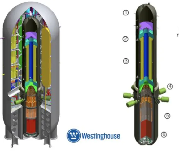
IRIS is an advanced medium size (1000 MWth) pressurized water reactor with an integral configuration suitable for modular deployment. A schematic of the IRIS integral layout is shown in Figure 1.
Figure 1. IRIS integrallayout
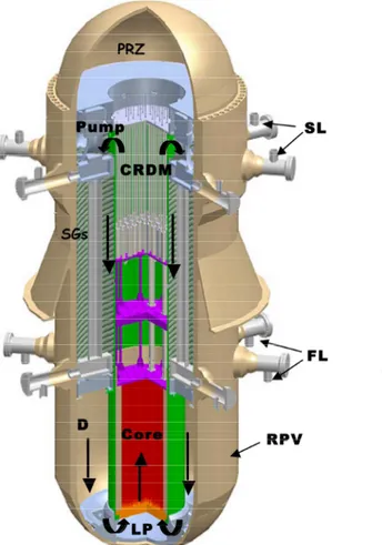
The reactor pressure vessel (RPV) hosts all the main reactor coolant system components: core, pressurizer, spool-type reactor coolant pumps, steam generators and control rod drive mechanisms. Eight once-through helical coil steam generators (SGs) are located around the riser and a canned pump is installed axially on top of each SG. The riser is defined by the extension of the core barrel. The “inverted hat” pressurizer occupies the RPV upper head.
The water flow path is from bottom to top through the core and riser, then circulation reverses and water is pushed downwards by the immersed pumps through the SG tubes. At the SG outlet, the
flow path goes along the annular downcomer region, outside the core, to the lower plenum and then back into the core.
The integral arrangement of the plant allows avoiding pressurized components, like the SGs, outside the RPV and largely reduces the size and number of RPV penetrations. Large LOCAs are eliminated and the number of possible small LOCAs is reduced. The RCS integral layout leads to a RPV diameter of 6.2 m, larger than conventional PWR, with a total height of about 22 m. A compact spherical steel containment, 25 m diameter, is part of the IRIS safety approach and is directly involved, through a coupled dynamic behaviour, in the passive mitigation strategy that enhances the safety and reliability of IRIS. The IRIS containment and safety systems are shown in Figure 2.
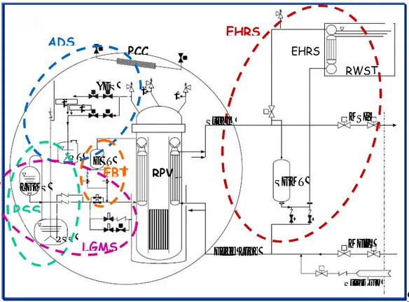
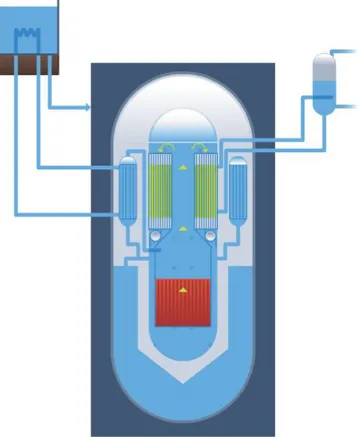
Figure 2 IRIS spherical containment and safety systems
As shown in Figure 2, the containment vessel consists of different compartments, in particular the Dry-Well and the Reactor Cavity, the Pressure Suppression Systems (PSS) and the Long Term Gravity Make-up Systems (LGMS). An Automatic Depressurization System (ADS) dumps steam in a Quench Tank (QT) both in case of accident and normal operational transients. Emergency Boration Tanks (EBT) are connected to the Direct Vessel Injection lines that, allows water injection into the vessel also from the LGMS and eventually back from the Reactor Cavity. The EHRS heat exchangers are contained in the Water Refuelling Storage Tank and intervene at isolated reactor condition. A Passive Containment Cooling System (PCCS) allows limiting the Containment Vessel (CV) pressure in case of EHRS unavailability.
The IRIS safety-by-designTM approach addresses small LOCA sequences by limiting and eventually stopping the loss of mass from the RPV rather than relaying on water injection by active or passive devices. That is achieved thanks to a large coolant inventory in the RPV and a compact, high design pressure containment, which, being thermodynamically coupled to the RPV during an accident, limits the blow-down by rapidly equalizing RPV and containment pressure, and by the RPV
EHRS EHRS RWST MSIV MFIV Start-up SGMT PCC RPV Steam Feed Line QT EBT 1 2 1 2 LGMS PSS ADS ADS ÈBT
PSS
LGMSdepressurization obtained by means of Emergency Heat Removal Systems that remove the decay heat by condensing steam directly through the SGs.
A typical sequence of LOCA events can be summarized in the following phases: 1) blow-down: the RPV depressurises and looses mass to the containment; 2) reactor trip, pump trip, reactor isolation and EHRS intervention, ADS actuation: the EHRS depressurizes the primary system without loss of mass while, if the ADS intervenes, it carries out the same function with loss of mass; 3) the PSS limits the containment pressure. Once the RPV-CV pressure equalization is reached, the blow-down phase ends; 4) the RPV-CV coupled system is depressurised by the EHRS that condenses steam and has the capability of removing more than the decay heat; 5) once pressure inside the RPV becomes lower than containment pressure, a reverse flow from the CV may occur through through the break and also a direct connection between reactor cavity and DVI lines; 6) a long term cooling phase follows the depressurization phase with the LGMS intervention and guarantees the core cooling. For the design certification and, more in general for studying the coupling phenomena between the containment and the primary system, an integral facility, called SPES-3, is under construction. A short description is reported in Section 3.
2.1.2 SPES-3 Facility
The SPES3 facility simulates the IRIS primary system, secondary5 system, safety systems and containment. The SPES3 facility process diagram is shown in Figure 3 and its axonometric view in Figure 4, whereas Table 2 reports a comparison of the main IRIS and SPES characteristics.
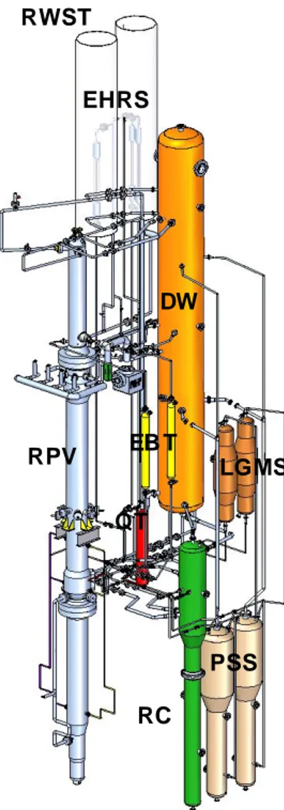
The IRIS integral configuration is maintained for all components of the primary system, except for the pumps, which are placed outside of SPES-3 reactor pressure vessel. The IRIS containment compartments are simulated in SPES3 by separate tanks, properly connected, representing the Dry-Well, two Pressure Suppression Systems (PSS), two Long Term Gravity Make-up System (LGMS), the Reactor Cavity (RC) and the Quench Tank (QT) for Automatic Depressurization System. Shape and dimensions are fixed in order to reproduce the trend of IRIS compartment volumes versus height. The Passive Containment Cooling (PCC) and a portion of the Direct Vessel Injection (DVI) lines are included in the containment as well.
Figure 3 SPES3 process diagram
The safety systems include the Emergency Boration Tanks (EBTs), the Emergency Heat Removal System (EHRS) and the Automatic Depressurization System (ADS). Three EHRS loops represent the four IRIS systems.
The design pressure of the primary and secondary systems, up to the main isolation valves is 17.25 MPa, with its corresponding saturation temperature of 353.5 °C. The primary and secondary side operating pressure is 15.5 MPa and 5.8 MPa, respectively. The containment design pressure is 1.5 MPa with its corresponding saturation temperature of 198.2 °C, while its operating pressure is 0.1013 MPa.
RWST DW RPV LGMS PSS RC EHRS EB T QT
Figure 4 SPES-3 axonometric view
Table 2 IRIS and SPES3 characteristic comparison System/Component IRIS SPES3 Primary side integral RPV yes yes apart the pump
Pumps Number 8 1
Core power (MW) 1000 6.5
EBT Number 2 2
Steam Generators 8 3
Secondary loops Number 4 3 SG tubes Number ~700 14, 14, 28
SG height (m) 8.2 8.2
SG tube average length (m) 32 32 Containment system yes yes
EHRS Number 4 3
RWST Number 2 2
Dry Well Number 1 1
PSS Number 2 2
LGMS Number 2 2
Quench Tank Number 1 1
The basis scaling parameters for SPES3 are: - Volume ratio 1:100;
- Same fluid properties (prototypical pressure and temperature); - Same component elevation;
- Area ratio 1:100, to maintain the same Resident time and velocity of fluid; - Same pressure drops.
The above listed choices lead to advantages and disadvantages:
- The full height provides prototypical distance between heat sources and heat sinks to properly simulate natural convection effects; both single phase and two phases natural convection loops can be simulated simultaneously; prototype and facility fluid velocities and residence times in the loops are the same; horizontal inter-phase areas (i.e. transfer area concentrations) are properly scaled.
- The prototypical fluid avoids distortions due to different fluid properties (i.e. the scaling analysis does not generate additional terms related to property distortions) and interpretation of the results is easier.
- The area of the side walls decreases only 10 times (not 100 times as the volumes) and this results in 10 times larger heat transfer area concentrations (energy exchange) and wall friction (momentum exchange).
- Some components (e.g. heat exchangers of EHRS) are simulated with limited number of tubes (i.e. not ideal for reproducing side effects).
According to the established scaling factors, SPES3 rod bundle power should be 10 MW. Being SIET power capability for SPES3 6.5 MW, the power to volume ratio is not preserved during the steady state, while it is rapidly matched at the beginning of the transient. The primary and secondary loop flow rates are therefore adjusted to maintain the steady state temperatures as in the IRIS plant.
The facility configuration is suitable to investigate the natural circulation loops that allow removing the decay heat during the long-term accidental transients.
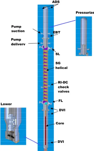
The SPES3 Reactor Vessel (RPV) is shown in Figure 1. The total height of the RPV is around 22 m with 0.65 m diameter. It consists of three main sections:
- the lower section that hosts the power channel, the lower plenum with closure plates and heater rod tightness system, the lower downcomer and DVI lower connections;
- the intermediate section that hosts the riser, the steam generator annular zones, the feed lines and steam lines connections, the pump delivery and DVI upper connections;
- the upper section that hosts the “inverted hat” pressurizer and ADS, the pump suction plenum, pump suction and connections to the Emergency Boration Tank (EBT) top lines
The rod bundle that reproduce the dimensions and pitch of the WEC 17 x 17 rod assembly, adopted in IRIS, consists of 235 heated and 1 dummy rod. The rods are indirectly heated and the axial power profile is constant. Two rods provides a greater power with 1.2 peak factor. The rods are maintained in their relative position by spacer grids located at different elevations. A double layer fuel bundle box envelops the rods and acts as downcomer barrel. A filler between the wall layers is chosen to scale correctly the thermal mass and the global heat transfer coefficient to compensate for the not correctly scaled side surface area.
The lower plenum contains a perforated cylinder that allows water from the downcomer to turn into the core. A tightness system, with high temperature resistant polymeric sealing disks, compressed between plates, allows the rods to exit the vessel bottom and join the electrical connections for power supply.
The SPES3 riser, over the core, is a cylindrical volume containing vertical tubes. Perforated plates are inserted in the riser to simulate Rod Cluster Control Assemblies (RCCAs), Control Rod Drive Mechanisms (CRDMs) and to adjust the pressure drops.
The eight IRIS Steam Generators are simulated by three helical coil SGs: one simulating four IRIS SGs, while the remaining two simulating each two IRIS SGs. The inner SGs have a single row of 14 tubes each (13 tubes will be used in the tests), while the outer one has two rows with totally 28 tubes (26 tubes will be used in the tests). The tubes have a prototypical outer diameter (17.48 mm), height (8.2 m) and length (32 m). Each SG is located in an annulus, obtained by vertical barrels concentric to the riser, and the tubes are maintained in their position by proper vertical plates. The tubes cross the vessel wall in correspondence of the Feed Line and Steam Line nozzles. In the nozzle area, the tubes bend to be welded on a plate between the nozzle flanges. This allows the feed water to redistribute in the tubes and steam to flow through the steam lines.
The “inverted hat” pressurizer (PRZ) reproduces the IRIS one; differently from IRIS, the SPES3 pressurizer adopts electrical heaters vertically inserted from the RPV top, to set pressure during steady conditions. Proper holes at the PRZ bottom simulate the IRIS surge path. The pump suction plenum is the volume outside the pressurizer hat.
A single outer pump simulates the eight IRIS internal pumps. The limited room inside the RPV does not allow fitting internal pumps, so a single outer pump distributes water to the three SG annuli through four separate nozzles. The mass flow balance is obtained by proper distribution plates at the SG top.
Nozzles on the RPV allow connecting the primary system to the DVI, the outer core by-pass, the pump suction and delivery, the ADS and the EBT balance lines.
Two Emergency Boration Tanks are connected to the RPV at the top, by the balance lines, and at the bottom through the DVI lines. They operate at the same RPV pressure.
The SPES3 secondary system consists of three loops simulating four with a loop lumping two IRIS secondary circuits. The feed lines and steam lines are simulated from the RPV nozzles up to the Main Feed Isolation Valves (MFIV) and Main Steam Isolation Valves (MSIV). The piping size is chosen to maintain the same pressure drops as in the IRIS plant, even with different routing.
The Emergency Heat Removal Systems consist of three loops with vertical tube heat exchangers immersed in the Refueling Water Storage Tank (RWST) and hot and cold legs joined to the Steam Lines (SLs) and Feedwater Lines (FLs), respectively. In particular, EHRS connected to the double secondary loop has a double heat exchanger. The heat exchangers are about 3 m high and contain 3, 3 and 5 tubes of 50.8 mm outer diameter.
The different IRIS containment compartments are simulated in SPES3 by tanks connected among them and to the RPV by piping. Such pipes do not exist in the IRIS plant and they are designed in terms of size and layout to limit their influence on the flow. The tank shape is chosen to reproduce the same volume trend versus height as in IRIS and, in specific cases, cylindrical tanks with variable sections are designed.
The three IRIS ADS trains are simulated in SPES3 by two trains: a single and a double train. Each train consists of a safety valve, a line to the Quench Tank and a line to the Dry Well. The line to the QT ends with a sparger that enhances the steam condensation under the water level.
The PCC is a condenser installed at the DW top which consists of an horizontal tube bundle, with the only requirement of removing specified power, without scaling the IRIS PCCS geometry (PCCS is an IRIS non-safety system and its functioning is foreseen only during beyond design basis accident sequences).
A thermal insulation is foreseen for all SPES3 tanks and piping to reduce the heat losses to the environment.
Break line systems are designed to simulate both split and double ended guillotine breaks. Break locations are foreseen at different elevations, in particular the lower break is on the horizontal part of the DVI and ends into the RC; the upper break is on the EBT to RPV balance line top and ends into the DW; the ADS break is on the single train, upstream of the safety valve and ends into the DW; the FL break ends into the RC; the SL break ends into the DW (i.e., steam and feed line break in containment are simulated). The exact break size is set by calibrated orifices that scale the IRIS plant pipe size.
The auxiliary systems provide water to the experimental facility at required temperature, pressure and mass flow. Direct current generators provide power to the fuel bundle and to the PRZ heaters. Some modifications to the already existing systems at SIET were needed to match IRIS requirements, in particular to the condensation system (heat sink), to the machinery cooling loop, to the air circuit for valve operation and instrumentation, to the power channel electrical connection. A large set of instruments (about 700) is installed on SPES3 to provide data both for the test run and analysis. It consists of conventional instrumentation (i.e. relative and absolute pressure transmitters, temperature sensors) and special instrumentation for two-phase flow measurement. The quantities directly measured by conventional instrumentation are: fluid and wall temperatures, absolute and differential pressures, velocity, volumetric flow, voltage and current, while special instrumentation
is used for void fraction and volumetric flow. Derived quantities are: level by differential pressure and density, mass flow by differential pressure and density, mass flow by volumetric flow and density, mass flow by volumetric flow and void fraction (wire mesh sensors and turbine), mass by level and density, heat losses by wall thermocouples, power by voltage and current.
The rod bundle is instrumented with 120 wall thermocouples distributed at different levels, with a greater density at the upper levels. They provide the rod cladding temperature and provide the signals for core protection against superheating.
2.2 SMR concept
2.2.1 Main design and operating characteristics
Westinghouse SMR is a 200 MWe class6 integrated pressurised water reactor in which all primary components (pressurizer, steam generators and control rod drive mechanisms) are located inside the reactor pressure vessel (pumps penetrate the RPV with impeller inside and engine ouside), Figure 6. The SMR passive safety systems and reactor internals including fuel assemblies are closely based on the AP1000® technology. The latest safety and security philosophies, licensed by the USNRC for AP1000® reactor, are implemented in the design of SMR.
Figure 6 Small Modular Reactor axonometric view
Legend of Figure 3:
1 Pressurizer 4 Reactor coolant pumps
2 hot leg Riser 5 Reactor Vessel Internals 3 Steam Generators 6 Reactor core
The SMR is designed to be completely fabricated in the factory and is scaled to be shippable by rail, then installed below ground level. The reactor comprises one factory-made module, about 25 metres high and 3.5 metres diameter. It has 18 to 24-month refuelling cycle [8].
The core is composed of 89 partial-height assemblies derivatives of the 17x17 WEC standard fuel used in the AP1000® reactor. The reactivity is controlled by soluble boron injection and 37 internal control rods. The core enrichment is lower than 5% and the length of active zone is 2.44 m.
The reactor vessel internals, based on the AP1000® design, are modified for the smaller core and to provide support for the internal control drive rod mechanisms.
Once-through straight-tube steam generators (SGs) are located around the hot leg riser above the core and have a compact configuration and an innovative approach for steam separation, out of the containment. The riser is defined by the extension of the core barrel.
Eight proven, horizontally-mounted axial-flow canned motor pumps, installed in the downcomer below the SGs, but above the core, provide the driving head for the reactor coolant system, which does not require a pump seal injection.
The pressurizer is integrated into the reactor vessel head, thus eliminating the need for a separate component.
The containment and the reactor safety systems are shown in Figure 7. The safety systems provide the emergency heat removal, the long-term gravity make-up, the highly borated injection of water and the long-term decay heat removal.
Figure 7 Westinghouse SMR: Containment and safety systems The containment outer diameter and height are 9.75 m and 27.13 m, respectively.
RPV, containment and safety systems is sufficient for 7 days, before providing outer supplies.
2.2.2 SMR Integral Test Facility
Being SMR mainly based on the AP-1000 proven technology, only design confirmatory tests are required. At present, no integral test facility is designed, but studies are under course to define design and scaling parameters for a test loop aimed at the confirmatory tests.
2.3 SMART concept
2.3.1 Main design and operating characteristics
System-integrated Modular Advanced Reactor (SMART) has been designed by KAERI (Korea Atomic Energy Research Institute) for diverse functions - electricity generation (up to 100 MWe), seawater desalination and district heating. One SMART reactor can supply power and water to a city with a population of 100,000. The design life is 60 years, with a 3-year refuelling cycle [3], [11].
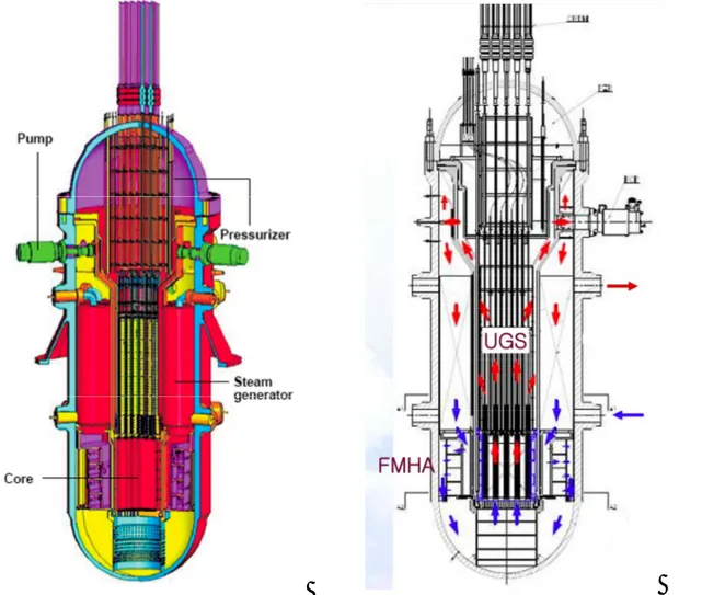
The SMART reactor is a 330 MWt pressurized water reactor with advanced safety features and an integral configuration. All the major primary components are installed inside the reactor pressure vessel, such as the reactor core, modular once-through steam generators, canned motor main reactor coolant pumps and self-pressurizing pressurizer. Figure 8 shows the structural configuration of the SMART reactor [10].
Legend of Figure 8
UGS: Upper Guide Structure FMHA: Flow Mixing Header Assembly
Four main coolant pumps (MCPs) are installed vertically at the top of the reactor pressure vessel (RPV). The reactor coolant flows upward through the core and enters from the top into the shell side of the steam generators, which are located at the circumferential periphery between the core support barrel and the RPV above the core. Additional innovations include the canned motor pumps, which has no pump seals, thus preventing loss of coolant associated with pump seal failure, and the passive pressurizer that does not have any active sprays and heaters. This pressurizer design eliminates complicated control and maintenance requirements and reduces the possibility of malfunction. The once-through steam generator consists of helically-coiled heat transfer tubes to produce superheated steam at 300 °C, in normal operating conditions. The small inventory of the steam generator secondary side water prohibits the water’s return-to-power following a steam line break accident.
The integral arrangement of the primary system allows to remove the large-size pipe connections between the major components, thus essentially preventing the occurrence of large break loss of coolant accidents (LBLOCA). The in-vessel pressurizer is designed to control the system pressure at a nearly constant level over the entire range of design basis events.
The safety systems designed to function passively on demand consist of a reactor shutdown system, passive residual heat removal system (PRHRS: 4 trains), safety injection system (SIS: 4 trains), shutdown cooling system (SCS: 2 trains), containment spray system (CSS: 2 trains), safety depressurization system (SDS: 2 trains) and reactor overpressure protection system (ROPS). The PRHRS prevents overheating and over-pressurization of the primary system in case of emergency events by removing the core decay heat through only natural circulation. The PRHRS has four independent trains with 50% heat removal capacity for each train. Two trains are sufficient to remove the decay heat generated in the core after the reactor trips. The SIS compensates for a coolant inventory loss to ensure that the core is always covered with water in the case of a small break loss of coolant accident (SBLOCA). It consists of four independent trains. The SCS cools the RCS coolant from a hot shutdown condition (200 °C) to a refuelling condition (50 °C). The SCS sucks up the coolant at the MCP suction duct, and then it discharges the coolant to the MCP discharge region through the shutdown cooling pumps and the heat exchangers. The RCS coolant is circulated through the SCS by a forced circulation after the system is actuated7. The ROPSs are provided by the pilot operated safety relief valves (POSRVs).
The major auxiliary systems of SMART consist of a component cooling system (CCS), purification system and make-up system. The function of the CCS is to remove heat generated in the main coolant pumps, control element drive mechanisms, pressurizer, and the internal shielding tank. Feedwater supplied from the condensate pump of the turbo-generator is used as coolant to remove heat. The purification system purifies the primary coolant and controls water chemistry to provide reliable and safe operation of the reactor core and all equipment in any mode of operation. The make-up system fills and makes-up the primary coolant in case of primary system leak and supplies water to the compensating tanks for the PRHRS; it consists of two independent trains, each with one positive displacement make-up pump, a make-up tank, piping and valves.
The turbine bypass system and condenser, in conjunction with the power cutback system, can accommodate 100% load rejection without reactor trip and without lifting either primary or secondary safety valves.
The core is maintained undamaged for 72 hours without any corrective actions by the operator. The reactor overpressure at any design basis event can be reduced through the opening of the pressurizer safety valve.
Reactivity control during normal operation is achieved by soluble boron and control rods. Burnable poison rods are introduced for flat radial and axial power profiles, which results in an increased thermal margin of the core. The nearly constant reactor coolant average temperature programme in the reactor regulating system improves load-follow operation performance in view of a stable pressure and water level within the pressurizer.
Four channel control rod position indicators contribute to simplification of the core protection system and to the enhancement of the system reliability.
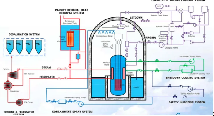
Figure 9 shows the safety systems and the primary system as well as auxiliary systems. The main data for the SMART reactor are reported in [11].
Preliminary safety analyses of SMART show that the reactor remains in a safe condition for all design basis events.
Figure 9 Simplified schematic diagram of the SMART NSSS
2.3.2 SMART Integral Test Facilities
Two Integral Test Facilities have been designed for simulating the behaviour of SMART reactor during postulated transients, in particular during a small-break loss of coolant accident (SBLOCA), and for validating various Korean thermal-hydraulic analysis codes, such as MARS and TASS/SMR: a small-scale integral test loop (VISTA-ITL: Experimental Verification by Integral Simulation of Transients and Accidents - Integral Testing Facility) and a large-scale integral test loop (SMART-ITL).
The VISTA-ITL, Figure 10, is a modified version of the VISTA facility [12]. The modifications concern the installation of different systems/components8 in order to simulate SBLOCA. The scaling ratios are: 1/2.77 and 1/1310 for elevation and volume, respectively. Electric heaters simulate the reactor core. Unlike the integrated arrangements of the reactor primary components, the facility primary components (reactor vessel, main coolant pump, steam generators, and pressurizer) are connected to each other by pipes for an easy installation of instrumentation and a simple maintenance. A single train of the secondary system removes the primary heat source and it consists of a feed water supply tank (FWST), a feed water line, a steam generator secondary side, and a steam line. Also a single train of the PRHRS is installed. The facility can be operated by a combination of manual and automatic operations. An automatic control system allows to control the major thermal hydraulic parameters following the operator’s instructions. In addition, several automatic control logics are implemented for start-up, heat-up, and transient operations. The controlled components include the electrical heating rods, the main coolant pump, the feed water and steam pressure control valves, the FWST heater, and the make-up pump.
Figure 10 Schematic diagram and axonometric view of the VISTA-ITL
The SMART-ITL, Figure 11, is a large ITL facility under construction at KAERI in order to: 1) investigate the integral performance of inter-connected components and possible thermal-hydraulic phenomena occurreing in the SMART reactor; 2) understand the various phenomena during the steady-state and transient conditions of SMART reactor and to validate its safety for various design basis events; 3) validate the related thermal-hydraulic models of the safety analysis code of TASS/SMR9. The detailed design is finished in 2010 and the erection of facility is in progress. The experimental campaign is planned to start in 2012. The Scaling Ratios have been calculated with Ishii & Kataoka’s scaling methodology [13] The main scaling ratios are: 1/1, 1/49 and 1/1 for
8steam pressurizer, safety injection system, break simulation system, steam generator bypass, hot leg, cold leg, PRHRS
makeup tank, and break measuring system.
elevation, area and volume ratio, and time, respectively. The power scaling is equal to 45% of Scaled Full Power (3 MW). The integral configuration has been maintained for RCP, except for SG. Moreover the hydraulic resistance and coolant distribution have been preserved, as well as the geometry and heat transfer of core heaters. Table 3 shows a comparison among some selected parameters of the IRIS and SMART reactors and their integral testing facilities. It is worth noting that the scaling ratio of SPES-3 is about double of SMART-ITL, so the former seems more suitable than the latter for investigating the physical thermal-hydraulic phenomena.
Table 3 Comparison of main parameters of SMART-ITL and SPES-3
Parameters SMART IRIS SMART-ITL SPES-3
Core Power (MWth) 330 1000 3 6.5
Design Temp. (°C) /Pres. (MPa) 360/17 352.5/17.25 370/18 352.5/17.25
Operating Pres. (MPa) 15 15.5 15 15.5
Nuclear Fuel type WH 17x17 WH 17x17 WH 17x17 WH 17x17
Reactor Diam./Height (m) 6 / 15.5 6.2 / 22 0.8 / 15 0.65 / 22
SGs number 8 8 4 3
PRHRS Trains number 4 4 4 3
RCPs number 4 4 4 1
SG Tubes number 375 700 15/15/15/15 14/14/28
SG Tube outer diameter
SG Tube Height/Length (m) 5/25 8.2/32 5/25 8.2/32
Core Heaters number 15048 23409 304 235
Scale Ratio (volume) - - 1/49 1/100
2.4 CAREM 25 concept
2.4.1 Main design and operating characteristics
The CAREM10 nuclear reactor has been developed by INVAP (Investigación Aplicada - Argentina) under contract with CNEA. It is a modular 100 MWt simplified pressurised water reactor with steam generators designed to be used for electricity generation (27 MWe) or as a research reactor or for water desalination (with 8 MWe in power cogeneration configuration) [11], [13].
CAREM has an integrated primary system within the reactor pressure vessel, self-pressurised and relying entirely on natural circulation and on passive features to accomplish the safety functions, Figure 12.
The Reactor Pressure Vessel (RPV) diameter is about 3.2 m and the overall length is about 11 m. Twelve identical ‘Mini-helical’ vertical once-through steam generators11 are placed in the annular zone between the riser barrel and the RPV wall, equally distanced. The location of the steam generators above the core produces natural circulation in the primary circuit. The secondary system circulates the fluid upwards within the tubes, while the primary fluid goes downwards in counter-current flow.
Steam generators are designed to withstand primary pressure without pressure in the secondary side and the steam system is designed to withstand primary pressure up to isolation valves (including the steam outlet / water inlet headers) in case of SG valve opening or closing. The natural circulation produces different flow rates in the primary system according to generated power (and removed). Under different power transients a self-correcting response in the flow rate is obtained.
10Central ARgentina de Elementos Modulares
Figure 12 Sketch of CAREM Reactor Pressure Vessel
The self-pressurizing feature of the RPV (steam dome) keeps the primary pressure very close to saturation pressure and guarantees a remarkable stability of the RPV pressure response in all the operating conditions. The control system is capable of keeping the reactor pressure practically at the operating set point through different transients, even in case of power ramps. The negative reactivity feedback coefficients and the large primary water inventory combined with the self-pressurisation feature make that behaviour possible with minimum control rod motion. Consequently the reactor has an excellent behaviour under operational transients.
The prototype core has 61 hexagonal cross section fuel assemblies (FA). Each FA contains 108 fuel rods, 18 guide thimbles and 1 about 1.4 m active length instrumentation thimble. Fuel is standard 3.4% enriched PWR fuel with burnable poison. The active core length is about 1.4 m. and the fuel cycle length is one year.
The safety systems are based on passive features and guarantee no need of active actions to mitigate the accidents for long time, Figure 13. They are duplicated and diversified to fulfil the redundancy criteria and the regulatory requirements.
The First Shutdown System is designed to shutdown the core when an abnormal situation or a deviation from normal situations occurs, and to maintain the core sub-critical during all shutdown states. That function is achieved by gravity dropping of 25 neutron-absorbing elements into the core. Each neutron-absorbing element is a cluster composed of a maximum of 18 individual rods, which are together in a single unit. Each unit fits well into guide tubes of each fuel assembly.
Control rods hydraulic drive mechanisms (CRD) avoid the use of mechanical shafts passing through the RPV, thus eliminating any possibilities of large LOCA. Their design is an important development in the CAREM concept [5]. Six out of twenty-five CRD allow the fast core shutdown. During the normal operation they are kept in the upper position, where a piston partially closes the outlet orifice and reduces the water flow to a leakage.
Figure 13 CAREM containment and safety systems
The Second Shutdown System is a gravity-driven injection device of borated water at high pressure. It actuates automatically when the Reactor Protection System detects the failure of the First Shutdown System or in case of LOCA. The system consists of two tanks located in the upper part of the containment. Each of them is connected to the reactor vessel by two pipe lines: one from the steam dome to the upper part of the tank, and the other from a position below the reactor water level to the lower part of the tank. When the system is triggered, the valves open automatically and the borated water drains into the primary system by gravity. The discharge of a single tank produces the shutdown of the reactor.
The Residual Heat Removal System has been designed to reduce pressure in the primary system and to remove the decay heat during a loss of heat sink. It is a simple and reliable system that operates condensing steam from the primary system in an emergency condensers. The emergency condensers are heat exchangers consisting of an arrangement of parallel horizontal U-tubes between two common headers. The top header is connected to the reactor vessel steam dome, while the lower header is connected to the reactor vessel at a position below the water level. The condensers are located in a pool filled with cold water inside the containment building. The inlet valves in the steam line are always open, while the outlet valves are normally closed; therefore the tube bundles are filled with condensate. When the system is triggered, the outlet valves open automatically and the condensate drains from the tubes. Steam enters the tube bundles from the primary system, it is condensed on the cold surface and the condensate returns to the reactor vessel by natural circulation. During the condensation process, heat is transferred to pool water by a boiling process. Evaporated water is then condensed in the suppression pool of the containment.
The Emergency Injection System prevents core uncovering in case of LOCA. In the event of such accident, the primary system is depressurised with the help of the emergency condensers to less than 1.5 MPa, with the water level over the top of the core. At 1.5 MPa, the low pressure water injection system comes into operation. The system consists of two tanks with borated water
connected to the RPV. The tanks are pressurized, thus when during a LOCA, pressure in the reactor vessel reaches 1.5 MPa, the rupture disks break and flooding of the RPV starts.
Three safety relief valves protect the integrity of the reactor pressure vessel against overpressure, in case of strong unbalances between core power and power removed from the RPV. Each valve is capable of producing 100% of necessary relief. The blow-down pipes from the safety valves are routed to the suppression pool.
Recent studies have explored scaling it up to 100 or 300 MWe.
2.4.2 CAREM Integral Test Facility
A High Pressure Natural Convection Loop (CAPCN) was designed, erected and operated for studying the thermal-hydraulic dynamic response of CAREM primary loop, including all the coupled phenomena that may occur during operational transients, and to provide data for validating thermal hydraulic codes, [15], [16]. The circuit configuration does not allow to simulate any kind of LOCA.
The CAPCN reproduces the CAREM primary loop and steam generators, while the secondary loop is designed just to produce adequate boundary conditions for the heat exchange. The core is simulated by electric heaters. For the dynamic tests the heaters are 1.2 m long. Water enters the heated section from the lower plenum, flows up through the riser to the upper plenum where a liquid-vapour interphase exists, then exits this plenum through an outer volume in contact with the steam generator. The steam generator has two coils, once through, secondary inside. The subcooled water (280 °C) flows down through the downcomer cold leg to the lower plenum. Natural circulation flow (1.08 kg/s) may be regulated by a valve in the cold leg and a by pass to the bottom of the riser. The secondary loop pressures (4.7 MPa) and cold leg temperatures (200 °C) are controlled through valves. The pump regulates the secondary flow (0.128 kg/s). The condenser is an air-cooled type with flow control. The (heaters, valves, pumps, etc.) control, data acquisition and operation follow-up are carried out from a control room, through a PC based, multi-node software (flexible enough to define any feedback loop). A gamma densitometer is available for void fraction measurement. The primary loop may operate in saturated or subcooled regimes, with a heating power up to 300kW and different hydraulic resistance. Elevation and volume scaling ratios are 1/1 and 1/280. The design pressure and temperature are: 15.0 MPa and 340°C. Figure 14 shows a simplified diagram of the facility.
The heaters bundle to be used for the CHF tests differs from that used for the dynamic ones, in order to have a configuration that allows to reach heat fluxes high enough to be sure to obtain departure from nucleate boiling for the complete range of pressures, flows and subcooling degree. The heated length is 400 mm. The seven rods bundle has two of the rods which allow 20% overpower. These rods have six thermocouples each in order to ensure the measurement of the exact location of CHF. The rest of the rods only have two thermocouples that guarantee CHF detection if it takes place on one of these rods. All the thermocouples are located near the upper end of the heated zone because the axial power distribution is uniform in the CHF heaters bundle.
Figure 14 CAPCN simplified process and instrumentation diagram
2.5 B&W mPower concept
2.5.1 mPower concept description
The mPower reactor, designed by Babcock & Wilcox (B&W) to be factory-made and railed to site, has a rated power output of approximately 125 MWe.
The B&W mPower is a simplified, passive, scalable, modular, light-water-cooled, advanced PWR that uses an integral arrangement in which the reactor core, steam generators and pressurizer are combined within a common pressure vessel. The control rod drive mechanisms and the reactor coolant pumps are also located inside the reactor vessel [17], [18]. It is modular in the sense that each unit is a factory-made module, whereas it is scalable having the capacity to match customer demand in nominal 125 MWe increments using 250 MWe turbine generators (also shipped as complete modules). Figure 15 illustrates prospective two-unit plant layout.
The B&W mPower is a direct descendent of the Otto Hahn reactor, which was used for surface ship propulsion from 1968 to 1979. It incorporates the key features of that reactor design, such as use of an integral, once-through steam generator, placement of nuclear supply system components inside a single pressure vessel, use of PWR type fuel assemblies, internal versus external reactor coolant pumps, internal versus external control rod drive mechanisms, passive safety systems, etc..
mPower inherent safety features include the absence of the large reactor coolant system piping and the lack of reactor vessel penetrations below the core top. The pant design also incorporates features aimed at increasing plant availability, as an extended refuelling cycle, fewer, smaller and simpler components, and use of proven, standard technology.
The containment building and other critical structures are located below ground level. Figure 16 shows a cutaway view of the containment building, which is a low-leakage, reinforced concrete,
steel-lined seismic category-I structure. Normal access is via two personnel hatches, and a removable equipment hatch on the top of the building provides access for large component replacement. The other buildings are situated below grade level, except for the reactor service building, which is located partially below grade level, and the turbine building, which is located above the ground level.
Figure 15 Two-Unit plant layout Figure 16 Containment building
The reactor pressure vessel is about 4 m diameter and 22 m high and it is supported by a support skirt at the lower vessel flange level, Figure 17 and Figure 18 .
The pressurizer is at the top of reactor vessel. The integral once-through steam generators, derived from naval designs, surround the central riser, below the pressurizer. The reactor coolant pumps are located in the downcomer annulus, just below the steam generator. The core is located at the bottom of the reactor vessel.
The B&W mPower has a “conventional core and standard fuel” (< 20 t) enriched to about 3.5÷5%, with burnable poisons, to give a four/five-year operating cycle between refuelling. 60-year service life is envisaged, as sufficient used fuel storage would be built on site for this.
The safety and supporting systems are aimed at protecting the core during accidents, providing long-term core cooling and preventing the release of radioactive materials to the environment, without reliance on AC power operator action for a least 72 hours following an accident; they are: emergency core cooling system, boron injection system, and reactor coolant inventory and purification.
The philosophy implemented in B&W mPower for coping with an accident does not rely on the plant-containment coupling.
The company intends to apply for design certification late in 2013, and a combined construction and operating licence (COL) application for TVA's Clinch River site in 2012, followed by construction start in 2015 and operation of the first unit in 2018. Meanwhile the design is in phase 1 of the Canadian Nuclear Safety Commission licensing process.
Figure 17 Reactor Pressure Vessel Figure 18 Primary loop and reactor coolant flow
No detailed information and data on B&W mPower reactor, systems and components, such as reactor process diagram, P&ID, number of SG, etc.) is available in literature.
2.5.2 B&W mPower Integral Testing Facility
The IST facility is under construction at the Centre for Advanced Engineering Research (CAER), in Bedford County, Virginia [19].
The Integrated Systems Test (IST) facility is aimed at: a) extending and enhancing the existing PWR database in order to confirm the mPower reactor design methodology and providing confidence for its application to an integral system design, such as for example the correlations used to cover the operating range of steam generators; b) demonstrating that the passive engineered safety systems and features of the reactor design are adequate to protect the plant and public health and safety, in other words evaluating the inherent safety margins associated with the reactor integral design and passive engineered safety features; c) demonstrating the adequacy of plant control systems, engineered safety features, and protection systems; d) providing an understanding of the application of incorporated safety features for design basis events, as well as of abnormal operating procedures and the emergency operating procedures; e) training of plant operators at least in the initial phases; f) confirming the methodology used in the design of the reactor system and transitions to the various states associated with natural circulation and reactor coolant make-up; g) documenting the reactor performance over a full spectrum of normal and transient operating conditions.
The facility instrumentation is more extensive than that foreseen in the reactor for the need of testing the control system and any algorithm that may be used in normal operation, design of components related to testing, training of operators and system behaviour understanding, including abnormal and emergency operation, and testing of the protection system and engineered safety features.
The turbine and associated equipment are not included in the IST facility, which incorporates simplified steam, feedwater and condensate systems.
The IST facility control system consists of a dedicated process controller; and provides a streamlined flow of diagnostic information and communication. The system also has the capability of supporting basic and advanced process control functions and any combination of input/output subsystems, including conventional, digital and wireless.
A reliable air system using two full-capacity compressors supplies the instrument air to the control devices.
IST test procedures have been developed based on the analysis of the B&W mPower reactor and the RELAP5 model of the integral reactor test loop and supporting systems, which has been used to verify scaling and to predict the results of the tests for comparison to expected plant performance, and to provide a basis for establishing acceptance criteria.
No information is provided regarding the scaling factors and other technical data on IST facility, but only a photo of IST loop tower and building is available [17].
2. 6 NuScale concept
2.6.1 Main design and operating characteristics
NuScale is an integral, modular, scalable, pressurized light-water reactor, designed by NuScale Power Inc., with passive safety features and rated thermal output of 160 MWt and electrical output of 45 MWe, Figure 19 [20], [21].
The design is based on MASLWR (Multi-Application Small Light Water Reactor) developed at Oregon State University in the early 2000s. Each module unit has its own combined containment vessel and reactor system, and its own designated turbine-generator set. The module unit can be combined as needed for obtaining the requested power generating capacity (up to 24 units). In a multi-module plant, one unit can take out of service without affecting the operation of the others. The modular feature allows the transportation of module components by barge, truck and rail so reducing costs and lead times.
The NuScale modules, control room, and spent fuel pool are all located below grade and housed in controlled-access buildings.
The reactor pressure vessel, housing core, steam generator, hot and cold legs, and pressurizer, is enveloped by a steel containment vessel, which is partially air-evacuated during power operation and is capable of relatively high pressures (3.1 MPa) during accident conditions, Figure 20. The partial vacuum in the high pressure containment reduces convection heat transfer without the use of “direct-contact” reactor vessel insulation; moreover the lack of appreciable amounts of air also enhances steam condensation rates during reactor vessel blow-down and prevents the formation of combustible concentrations of hydrogen mixtures in the event of a severe accident.
Figure 20 Integrated reactor pressure vessel and high pressure containment
The high-pressure containment vessel is submerged in water in a safety related reactor pool and is covered by an individual concrete impact shield. All the modules and the reactor pool are enclosed in a single confinement building.