INTERNATIONAL ORGANISATION FOR STANDARDIZATION
ORGANISATION INTERNATIONALE NORMALISATION
ISO/IEC JTC1/SC29/WG11
CODING OF MOVING PICTURES AND AUDIO
ISO/IEC JTC1/SC29/WG11
MPEG2009/m16475
April 2009, Maui, Awaii, USA
Title
A proposal for Video Signature Tool and Video Fingerprinting
Status
Proposal
Authors
Marzia Corvaglia, Fabrizio Guerrini, Riccardo Leonardi, Pierangelo
Migliorati, Eliana Rossi (DEA-SCL, University of Brescia, Italy)
Contacts: [email protected]
Table of Contents
Abstract... 2
1 Introduction... 2
2 The proposed Video Signature technology... 2
2.1 Main idea ... 2
2.2 Low level descriptors... 3
2.2.1 Dominant Color Descriptor (DC) ... 3
2.2.2 Dominant Luminance Descriptor (DY) ... 5
2.2.3 Color Layout Descriptor (CL) ... 6
2.2.4 Luminance Layout (LL) ... 8
2.2.5 Ordinal Measurement (OM) ... 9
2.2.6 The Motion Activity Map (MAM) ... 10
2.2.7 The Directions of Motion Activity (DMA) ... 11
2.2.8 Header Descriptor (HD) ... 13
2.3 The proposed Video Signature ... 13
2.3.1 Introduction... 13
2.3.2 Video Signature syntax... 14
2.3.3 Experimental evaluation for automatic feature identification ... 17
2.4 The proposed method for copy detection ... 18
2.4.1 Feature extraction ... 18
2.4.2 Feature processing ... 18
2.4.3 Filtering... 19
2.4.4 Matching ... 19
3 Performance evaluation of the proposed technology... 20
3.1 Independence results... 20
3.2 Robustness results... 21
3.3 Performance measures ... 22
3.3.1 Video Signature size ... 22
3.3.2 Extraction and Matching Complexity... 22
Conclusions... 22
Abstract
In this document we present and evaluate a video signature system, proposed by Signals and Communications Laboratory – Department of Electronic for Automation, University of Brescia (Italy). The proposed Video Signature is MPEG-7 compliant.
The technology is based on the use of many different features (color, motion, etc.). The preliminary studies show that these features have relevant characteristics in their development in time. The testing results prove that the features act differently with respect of the type and modification the query suffered.
1 Introduction
The Video Signature is the natural extension of the Image Signature Descriptor, which has been recently standardized, to the video signals.
The purpose of the Image Signature is to find identical or modified images of a given query image. The purpose of the Video Signature is, given a query video (also called ‘copy’), to find the video (also called ‘original clip’) where the query has been taken from, even if:
• the query has been attacked, that is it has been edited, modified, re-encoded, etc.; • the query has been immersed in a dummy video;
• both.
The Video Signature can be extracted from both query and original clips. The basic idea consists of detecting the original clip comparing the Video Signatures of the query with the Video Signature of the original clips. This problem is better known in the literature as Content Based Copy Detection (CBCD).
The proposed system is based on the use of multiple visual features, considering their development in time along both queries and original clips. The experimental results show that PARTIAL queries (query immersed in dummy video and attacked) have a characteristic development. The results also show that the relevance of the considered visual feature depends on the video where the features have been extracted.
The experimental results under Call for Proposal conditions are quite low but they confirmed the different impact of features on the video and also suggested that one feature can be characteristic of a specific attack.
2 The proposed Video Signature technology
2.1
Main idea
The proposed technology is based on the assumption that multimedia contents (videos in this Call for Proposal) can be described by several features. Each feature characterizes a specific aspect of the video: color, motion, etc. In this sense, it is hard to univocally define a video signature choosing only one feature. An alternative solution is trying to determine a method for automatically identify the best feature for each video or for each part of it (temporal segment). In
Figure 1
the framework of the proposed method is shown. For each video (original clip) and each query (copy), a set of features are extracted (red box), processed (green box) and then stored in two separate databases. The processing of each clip/query is performed in order to create Video Signatures (VS) which are optimized by using the most characteristic feature for the considered clip/query. Query signature (VSq) and videos signatures (VSv) are then used in copy detectionapplication: filtering and matching (respectively yellow and blue boxes). The purpose of the filtering is the detection of DIRECT and PARTIAL queries as defined in this Call for Proposal [MPEG-VS-08] [MPEG-VS-09].
Figure 1 Video Signature System.
In the following Sections, first the considered features are described. Then the video signature is defined on the basis of some experimental considerations. Finally the method for copy detection is reported with the experimental results.
2.2
Low level descriptors
In MPEG-7 terminology a Descriptor (D) is a possible representation of a feature. One feature can be represented by many Desciptors; for example the feature ‘color’ can be represented by Descriptors Dominant Color, Color Layout, etc.
Following the Descriptor considered for Video Signature are specified. Some of them are MPEG-7 compliant (Dominant Color and Color Layout), some other are not standard (Dominant
Luminance, Ordinal Measure, Motion Activity Map, Directions of Motion Activity).
2.2.1
Dominant Color Descriptor (DC)
This descriptor specifies a set of dominant colors in an arbitrarily shaped region. In our implementation we have followed the indications given by the MPEG-7 Standard [MPEG7-01], [MPEG7-book-02], [CTD-2001], using the software implementation proposed in the Reference Model. In the next paragraphs we will give a brief description of the DC, specifying how we have set the various parameters in our experiments. For a more detailed description, refer to [MPEG7-01], [MPEG7-book-02], [CTD-2001].
General description
A set of dominant colors in a region of interest or in an image provide a compact description that is easy to index. Colors in a given region are clustered into a small number of representative colors.
The feature descriptor consists of the representative colors, their percentages in the region, spatial coherency of the dominant colors, and color variances for each dominant color.
In order to compute this descriptor, the colors present in a given image or region are first clustered. This results in a small number of colors and the percentages of these colors are calculated. As an option, the variances of the colors assigned to a given dominant color are also computed.
A spatial coherency value is also computed that differentiates between large color blobs versus colors that are spread all over the image.
The binary semantics of the dominant color descriptor specifies 3 bits to represent the number of dominant colors and 5 bits for each of the percentage values. The color space quantization is not part of the descriptor.
The optional color variances are encoded at 3 bits per color with non-uniform quantization. This is equivalent to 1 bit per component space in the 3-D color spaces.
Specific description Size
This field element, which is only present in the binary representation, specifies the number of dominant colors in the region. The maximum allowed number of dominant colors is 8, the minimum number of dominant colors is 1.
We have set this value to 8. ColorSpacePresent
This element field, which is only present in the binary representation, indicates the presence of the ColorSpace element. If set to 0, ColorSpace is not present and RGB color space is used.
We have used the RGB colo space. ColorSpace
This element is defined in the subclause related to Color Space. ColorQuantizationPresent
This element, which is only present in the binary representation, signals the presence of the ColorQuantization element. If set to 0, ColorQuantization is not present and uniform color quantization of the components to 5 bits is used.
ColorQuantization
This element is specified in the subclause related to Color Quantization. VariancePresent
This field, which is only present in the binary representation, indicates the presence of the color variances in the descriptor.
SpatialCoherency
This element specifies the spatial coherency of the dominant colors described by the descriptor. It is computed as a single value by the weighted sum of per-dominant-color spatial coherencies. The weight is proportional to the number of pixels corresponding to each dominant color. Spatial coherency per dominant color captures how coherent the pixels corresponding to the dominant color are and whether they appear to be a solid color in the given image region. Spatial coherency per dominant color is computed by the normalized average connectivity (8-connectedness) for the corresponding dominant color pixels.
The weighted sum of per-dominant-color spatial coherencies is normalized from 0 to 1, then non-uniformly quantized to the range from 1 to 31 as follows. Normalized values less than 0.7 are set to 1, while values between 0.7 to 1 are uniformly quantized to the range 2 to 31. 0 is used to signal that this element is not computed (note that if it is not computed it does not mean that the spatial coherency is low).
Values
This element specifies an array of elements that hold percentages and values of colors in a visual item. The array elements consist of Percentage, ColorValueIndex and ColorVariance.
Percentage
This element describes the percentage of pixels that have been associated to a color value. The percentage value is uniformly quantized to 5 bits with 0 corresponding to 0 percentage and 31 corresponding to 100%. Note that the sum of the Percentage values for a given visual item does not have to be equal to 100%.
ColorValueIndex
This is an integer that specifies the index of the dominant color in the selected color space as defined in ColorQuantization. The number of bits for each component is derived from the ColorQuantization element. The dimension of this vector depends on the selected color space. ColorVariance
This is an element that specifies an integer array containing the value of the variance of color values of pixels corresponding to the dominant color in the selected color space, i.e.:
(
)
∑
− = − = 1 0 2 1 N k kj j j N m p CVwhere j indexes the color component, mj is j-th component of the dominant color, pkj is j-th
component of the k-th pixel value, and the summation is over N pixels corresponding to the dominant color under consideration.
The dimension of this vector depends on the selected color space. Each component is quantized to 1 bit, with “0” corresponding to low variance and “1” corresponding to high variance. The quantization threshold is equal to 0.005 of the squared color component value range.
Metric operator
To evaluate the similarity of two I-frames I1 and I2,
€
DDC(I1, I2), each one of them described by
its DCs, we have adopted the Earth Mover Distance (EMD), as proposed in [EMD-1998].
This represent a distance measure between two statistical distributions, and reflects the minimal amount of work that must be performed to transform one distribution into the other by moving “distribution mass” around. This is a special case of the transportation problem from linear optimization, for which efficient algorithms are available.
More specifically, in our implementation, the feature descriptor consists of the Nc=8 more representative colors and their percentages, Pi, i=1, 2, …, 8, in the image.
The spatial coherency of the dominant colors and the color variances for each dominant color have not yet been taken into account in the current implementation.
As a low-level distance measure between two color values (required in the implementation of the EMD estimator), we have adopted the Euclidean distance, evaluated in the Luv color space. In case of comparison of two video segments, we have evaluated the distances between every couple of corresponding I-frames, and then we have averaged the obtained values over the entire temporal span of the considered video segments.
2.2.2
Dominant Luminance Descriptor (DY)
This descriptor is a simplification of the dominant color, described above. General description
This descriptor is analogous to the Dominant Color Descriptor and represents a set of dominant luminance in the image. The computation of this descriptor follows the computation of the Dominant Color Descriptor but only the luminance distribution is taken into account.
This descriptor can be useful when the color information is not present, for example if the image is gray scale.
Metric operator
To evaluate the similarity of two I-frames I1 and I2,
€
DDY(I1, I2), each one of them described by its
DYs, we have adopted the Earth Mover Distance (EMD), as proposed in [EMD-1998]. DDL representation syntax
For MPEG-7 description, we do not need to define a new Descriptor because we can use the Dominant Color syntax [MPEG7-01]. The difference will be in the instance of the Descriptor where the ‘ColorSpace’ and the numbers of values will be different from the Dominant Color.
2.2.3
Color Layout Descriptor (CL)
This descriptor specifies the spatial distribution of colors for high-speed retrieval and browsing. This descriptor can be applied to images or arbitrarily shaped image regions. When applied to a video segment or a moving region, the descriptor specifies the spatial distribution of the color of a representative frame selected from the corresponding video segment or a representative region selected from the corresponding moving region.
In our implementation we have followed the indications given by the MPEG-7 Standard [MPEG7-01], [MPEG7-book-02], [CTD-20[MPEG7-01], using the software implementation proposed in the Reference Model.
In the next paragraphs we will give a brief description of the CL, specifying how we have set the various parameters in our experiments. For a more detailed description, refer to [MPEG7-01], [MPEG7-book-02], [CTD-2001].
General description
The CL is designed to capture the spatial distribution of color in an image or an arbitrary-shaped image region.
The CL is a compact descriptor that uses representative colors on a grid followed by a DCT (Discrete Cosine Transform) and encoding of the resulting coefficients.
The feature extraction process consists of two parts. Grid based representative color selection and DCT transform followed by quantization.
More specifically, an input image is divided into blocks and their average colors are derived. Note that it is implicitly recommended that the average color be used as the representative color for each block. This partitioning process is important to guarantee the resolution or scale invariance. The derived average colors are transformed into a series of coefficients by performing a DCT. A few low-frequency coefficients are selected using zigzag scanning and quantized to form a CL. The color space adopted for CL is YCbCr.
The default recommended number of bits is 63. This includes six Y coefficients, and three each of Cr and Cb coefficients.
The dc values are quantized to 6 bits, and the remaining to 5 bits each. Specific description
This is a 1- or 2-bit integer field, which is only present in the binary representation, that specifies the number of coefficients included in the descriptor.
numOfYCoeff, numOfCCoeff
These elements specify the number of coefficients for each color component (Y and Cb/Cr). The possible number is one of 1, 3, 6, 10, 15, 21, 28, and 64. When not specified, these elements are set to their default values: 6 for Y and 3 for Cb and Cr.
numOfYCoeffIndex, numOfCCoeffIndex
These elements fields, which are only present in the binary representation, indicate specify the NnumOfYCoeff and NnumOfCCoeff for the cases not covered by CoeffPattern.
YDCCoeff, YACCoeff, CbDCCoeff, CbACCoeff, CrDCCoeff, CrACCoeff
These elements specify the integer arrays that hold a series of zigzag-scanned DCT coefficient values.
YDCCoeff
The first quantized DCT coefficient of the Y component. YACCoeff
The second and the successive quantized DCT coefficients of Y component. CbDCCoeff
The first quantized DCT coefficient of the Cb component. CbACCoeff
The second and the successive quantized DCT coefficients of Cb component. CrDCCoeff
The first quantized DCT coefficient of the Cr component. YACCoeff
The second and the successive quantized DCT coefficients of the Y component. In the DDL representation, separate elements (YACCoeff2, YACCoeff5, YACCoeff9, YACCoeff14, YACCoeff20, YACCoeff27 and YACCoeff63) are used to cover all valid array lengths. CbACCoeff
The second and the successive quantized DCT coefficients of the Cb component. In the DDL representation, separate elements (CbACCoeff2, CbACCoeff5, CbACCoeff9, CbACCoeff14, CbACCoeff20, CbACCoeff27 and CbACCoeff63) are used to cover all valid array lengths. CrACCoeff
The second and the successive quantized DCT coefficients of the Cr component. In the DDL representation, separate elements (CrACCoeff2, CrACCoeff5, CrACCoeff9, CrACCoeff14, CrACCoeff20, CrACCoeff27 and CrACCoeff63) are used to cover all valid array lengths. These coefficients are derived as described in [MPEG7-01], [MPEG7-XM-01], [CTD-2001]. It should be noted that this process must be performed on each color component independently. The DCT coefficients of each color component are derived from the corresponding component of local representative colors. The selection algorithm of local representative colors is not normative.
Metric operator
To evaluate the similarity of two images, each one of them described by its CLs, we have adopted the metric proposed in [MPEG7-XM-01], [CTD-2001].
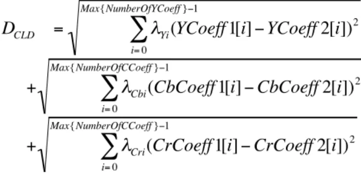
More specifically, the distance between two descriptor values CL1(YCoeff1, CbCoeff1, CrCoeff1) and CL2 (YCoeff2, CbCoeff2, CrCoeff2) should be calculated as follows.
€
D
CLD=
λ
Yi(YCoeff 1[i] − YCoeff 2[i])
2i= 0 Max{NumberOfYCoeff }−1
∑
€
+
λ
Cbi(CbCoeff 1[i] − CbCoeff 2[i])2
i= 0
Max{NumberOfCCoeff }−1
∑
€
+
λ
Cri(CrCoeff 1[i] − CrCoeff 2[i])2
i= 0
Max{NumberOfCCoeff }−1
∑
Here, the coefficients lamdas denote weighting values for each coefficient.
They should be decreased according to the zigzag-scan-line order [MPEG7-XM-01].
Table 1 shows an example of weighting values for default descriptor. They are designed to be implemented using only shift operations. If the NumberOf(X)Coeff is different between CL1 and CL2, the missing element values on the shorter descriptor should be regarded as 16(0x10), means 0 value on AC coefficient fields, or the redundant element values on the longer descriptor should be ignored.
Table 1 : An example of weighting values for the default descriptor.
Coefficient Order (X) 0 1 2 3 4 5 Y 2 2 2 1 1 1 Cb 2 1 1 Cr 4 2 2
In case of comparison of two video segments, we have evaluated the distances between every couple of corresponding I-frames, and then we have averaged the obtained distance values over the entire temporal span of the considered video segments.
2.2.4
Luminance Layout (LL)
The Luminance Layout descriptor is a compact descriptor that represents the spatial distribution of luminance in an image or frame.
General description
To compute this descriptor, the image is first partitioned into blocks following a grid base approach. Then, the average luminance per each block is derived. The descriptor consists in the average luminance values of each block (
Figure 2
).To evaluate the similarity of two elementary video segments, each one of them described by its luminance layout, we adopted the L1 distance.
Figure 2 Example of Dominant Luminance Descriptor
DDL representation syntax
Also in this case, we do not need to define a new Descriptor because MPEG-7 Visual Part [MPEG7-01] provides a set of tools which are sufficient for the standard description of the Dominant Layout: Grid layout, Dominant Color, etc.
2.2.5
Ordinal Measurement (OM)
This Descriptor is kind of evolution of the Luminance Layout (LL) described above. General description
The Ordinal Measurement consists in partitioning the image into N blocks, as shown in
Figure 1
; the obtained blocks are sorted using their average luminance and the Descriptor is given by the uses of the rank ri of each block i: OM = (r1, r2, ..., rN) [OM-2007].Metric operator
The distance measure between two frames/images I1 and I2 is given by the norm L1: D =|I1(i) − I2(i)|
DDL representation syntax
<!-- ########################################################### --> <!-- Definition of Ordinal Measurement D --> <!-- ########################################################### --> <complexType name="OrdinalMeasurementType" final="#all">
<complexContent>
<extension base="mpeg7:VisualDType">
<attribute name=”BlockNum” type=”mpeg7: unsigned8” use=”required”/>
<sequence>
<element name=”rank” type=”mpeg7:unsigned8”/> </sequence>
</extension> </complexContent> </complexType>
Descriptor components semantics BlockNum
rank
This field represent a the rank of each i block with i=1,…,BlockNum.
2.2.6
The Motion Activity Map (MAM)
This descriptor specifies the spatial distribution of motion activity, and can be applied to video segments.
In the next paragraphs we will give a description of the MAM, specifying how we have set the various parameters in our experiments.
For a further description of the general idea of MAM, refer to [MD-2001], [BXL-2005], [MAM-2002].
General description
When we are considering global motion changes instead of individual objects moving in the scene, we can view the motion of a video segment from the image plane along its temporal axis, as suggested in [MAM-2002], by generating the so-called MAM (Motion Activity Map).
The utility of motion activity maps is twofold. On the one hand, it indicates if the activity is spread across many regions or restricted to one large region, showing a view of spatial distribution of motion activity. On the other hand, it expresses the variations of motion activity over the duration of the video, displaying the temporal distribution of the motion activity.
Motion activity map is an image synthesized from motion vector field. The intensity of MAM pixel is the numeric integral of the motion activity on the spatial grid and represents the measurement of motion during a period of time. The motion activity can be any function of video motion vector such as the modulus of motion vector, the frequency of motion vector orientation changing, etc.
Specific description
As the MAM is the image-based representation of the motion vector field, the length of video segment influences the appearance of MAM heavily.
A pixel in MAM represents the accumulated motion activity, the higher intensity of MAM pixel is, the more motion activity is.
Therefore, a region-based representation of the MAM can be adopted for the view of spatial distribution of motion activity. The MAM can be further segmented into different regions according to the pixel intensity.
There are two types of video segmentation processes in MAM generation. One is the temporal segmentation of video; the other is the spatial segmentation of MAM. Many video segmentation algorithms can accomplish the temporal segmentation. In spatial segmentation, the MAM could be segmented into different image regions according, for example, to the pixel intensity of MAM.
The value of each point (i, j) in the image ISMAM is the numeric integral of the Motion Vectors
(MV) magnitudes computed in its position, and represents the measurement of the amount of motion during a specific period of time.
In more detail, the (i, j)-th value of the MAM, ISMAM(i, j) associated to a specific MB(i, j) of the
considered image, is given by:
ISMAM(i, j) =
€
1
Ts
€
| MV (i, j,t) |
t= 0 Ts−1∑
Where Ts is the temporal duration (expressed as the number of frames involved) of the considered elementary video segment, MV(i, j, t) is the motion vector associated to the macro-block MB(i,j), of the t-th frame of the considered elementary video segment.
Metric operator
To evaluate the similarity of two elementary video segments, each one of them described by its motion activity map, ISMAM1 and ISMAM2,
€
DMAM(ISMAM1, ISMAM2), we have adopted the L1
distance.
€
DMAM(ISMAM1, ISMAM2) =
€
1
Ntot
€ i= 0 Ni−1∑
| ISMAM 1(i, j) − ISMAM 2(i, j) | j= 0Nj−1
∑
Where Ntot = Ni . Nj represent the total number of consider MB in one image, Ni and Nj represent the number of MB in the horizontal and vertical directions, respectively, ISMAM1(i, j) and ISMAM2(i,
j) represent the (i, j)-th value of the MAM, associated to the specific MB(i, j) of the considered motion image, indexed as 1 or 2.
In case of comparison of two sets composed by groups of elementary video segments, we have evaluated the distances between every couple of video segments, and then we have averaged the obtained values.
DDL representation syntax
<!-- ########################################################### --> <!-- Definition of MotionActivityMap D --> <!-- ########################################################### --> <complexType name="MotionActivityMapType" final="#all">
<complexContent>
<extension base="mpeg7:VisualDType">
<attribute name=”BlockDim” type=”mpeg7:unsigned2” use=”required”/>
<sequence>
<element name=”MAM” type=”mpeg7:IntegerMatrixType”/> </sequence>
</extension> </complexContent> </complexType>
Descriptor components semantics BlockDim
The size of blocks used to partition the original image. It can assume three values 0,1 or 2 corresponding to a 4x4, 8x8 or 16x16 bock size respectively.
MAM
This field represent a 2D matrix which contains the values of the motion activity in each block of the considered image.
2.2.7
The Directions of Motion Activity (DMA)
This descriptor specifies the main directions of motion activity, and can be applied to elementary video segments.
In the next paragraphs we will give a description of the DMA, specifying how we have set the various parameters in our experiments.
For a further description of the general idea of DMA, refer to [BXL-2005], [MD-2001], [MAM-2002].
Besides the spatio-temporal motion properties described by a MAM, for a video that either contains several moving objects or is filmed by a moving camera, the approximate dominant motion directions can be very informative too [BXL-2005], [MD-2001].
Specific description
Let MVi_x and MVi_y denote the two components of the motion vector MV of the i-th Macro Block (MBi), Ns the total number of MB in the considered image, the total amount of motion along each of the four directions can be represented as a vector DM = (Up, Down, Left, Right): Up =
€
MVi _ y,
i= 0 Ns∑
if MVi_y > 0; Down =€
MVi _ y,
i= 0 Ns∑
if MVi_y ≤ 0; Left =€
MVi _ x,
i= 0 Ns∑
if MVi_x > 0; Right =€
MVi _ x,
i= 0 Ns∑
if MVi_ x ≤ 0;A vector DM is then computed for each P and B frame; it is then straightforward to extend this descriptor to characterize a video segment by computing the average value over all P, and B frames contained in the considered video segment.
Metric operator
To evaluate the similarity of two DMDs, DM1 and DM2, associated to two elementary video segments IS1 and IS2,
€
DDMA(DM1, DM2), each one of them described by its DM vector, we have
adopted the L1 distance.
€ DDMA(DM1, DM2) = =
€
1
4
€
|Up1− Up2 | + | Down1− Down2 | + | Left1− Left2 | + | Right1− Right2 |
(
)
In case of comparison of two sets composed by groups of elementary video segments, we have evaluated the distances between every couple of elementary video segments, and then we have averaged the obtained values.
DDL representation syntax
<!-- ########################################################### --> <!-- Definition of DirectionsMotionActivity D -->
<!-- ########################################################### --> <complexType name="DirectionsMotionActivityType" final="#all">
<complexContent>
<extension base="mpeg7:VisualDType"> <sequence>
<element name="Up" type="mpeg7:unsigned8"/> <element name="Down" type="mpeg7:unsigned8"/> <element name="Left" type="mpeg7:unsigned8"/> <element name="Right" type="mpeg7:unsigned8"/> </sequence>
</extension> </complexContent>
</complexType>
Descriptor components semantics Up
This field represents an indicator of the amount of motion in the up direction. Down
This field represents an indicator of the amount of motion in the down direction. Left
This field represents an indicator of the amount of motion in the left direction. Right
This field represents an indicator of the amount of motion in the right direction.
2.2.8
Header Descriptor (HD)
The header is a compact representation of the main general characteristic of a video. The considered characteristics are: image width and height, frame rate in frame per second, color information and gop information.
General description
The information available in HD are:
• the image width and height indicate the dimensions in pixels of the frames; • the color information indicates if the video is a color or gray scale video; • the gop information indicates if the video gop is variable or uniform;
• the number of different gops is indicated and then follows the gop values and the number of gops whose value is the one indicated.
An example of header is the following:
720 576 25 color 4 4 1 10 1 12 369 18 4
In this example the image width is 720 pixels, image height is 576 pixels, the frame rate is 25 fps, the video is a color video and there are 4 different gops, 1 gop with value 4, 1 gop with value 10, 369 gops with value 12 and 4 gops with value 18.
For this Descriptor the MPEG-7 already provide the tools for its XML representation. This tools belong to MDS part of MPEG-7 standard [MPEG7-02].
2.3
The proposed Video Signature
2.3.1 Introduction
As introduced in Section 2.1, the basic idea followed to define the proposed Video Signature (VS) considers that given a certain temporal segment of a video clip, depending on the content of this segment, there some Descriptors that are more suitable than others to describe this segment in order to facilitate the copy detection of the considered segment itself.
Taking into account this general consideration, we have implemented a procedure suitable to analyze every segment of the considered video clip in order to decide which descriptors would represent efficiently (with respect to the task of copy detection) the current segment. The efficiency is then described by a weight associated to each Descriptor.
In order to guarantee a certain degree of scalability, we can also include in a Segment-DS a refinement which describes each segment using another, more detailed Segment-DS, and so on. For example, a first level of resolution could be the shot, a second level could be the micro-segment, a third level could be the GOP, and a final level could be every single frame. Anyway, the Segment-DS is very flexible, and therefore many other possibilities could be easily introduced. This possibility of scalable temporal segmentation is very important for at least two reasons.
• First, being available a scalable description of the temporal segmentation, it allow for example the possibility to a video search engine with low computational power to consider only the first level of the segmentation giving the results with a certain level of resolution. This resolution can anyway be improved considering also the further resolution levels.
• Second, the search engine could use the first level of temporal resolution to obtain a draft localization of the query copy, and then it could refine the detection resolution considering also the other resolution levels.
2.3.2 Video Signature syntax
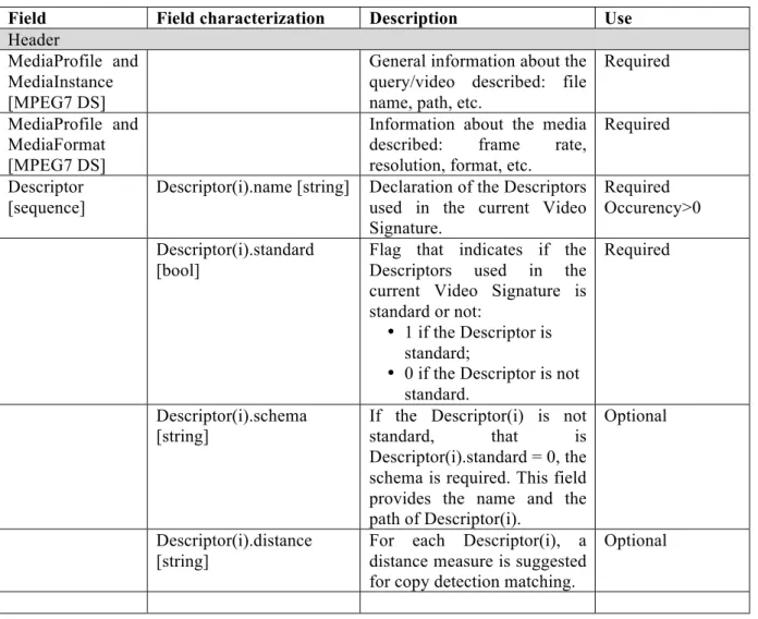
Video Signature syntaxThe logical structure of the proposed Video Signature is described in Table 2. The Video Signature is the same for both query and video. Video Signature is an MPEG-7 compliant Description Scheme (DS).
Table 2. Video Signature Syntax.
Field Field characterization Description Use
Header
MediaProfile and MediaInstance [MPEG7 DS]
General information about the query/video described: file name, path, etc.
Required MediaProfile and
MediaFormat [MPEG7 DS]
Information about the media described: frame rate, resolution, format, etc.
Required Descriptor
[sequence]
Descriptor(i).name [string] Declaration of the Descriptors used in the current Video Signature.
Required Occurency>0 Descriptor(i).standard
[bool]
Flag that indicates if the Descriptors used in the current Video Signature is standard or not:
• 1 if the Descriptor is standard;
• 0 if the Descriptor is not standard.
Required
Descriptor(i).schema [string]
If the Descriptor(i) is not standard, that is Descriptor(i).standard = 0, the schema is required. This field provides the name and the path of Descriptor(i).
Optional
Descriptor(i).distance [string]
For each Descriptor(i), a distance measure is suggested for copy detection matching.
Data
TemporalDecomp osition [MPEG7 DS]
For each video, a global temporal decomposition is required. The decomposition can be defined with a proprietary algorithm. Required VideoSegment [MPEG7 DS] [sequence] MediaTime(i) [MPEG7 DS]
Each Video Segment is characterized by the starting time and by the duration (frame number, seconds, etc.).
Required
Descriptor(i) [MPEG7 DS | proprietary]
According with the information in the Header, each Video Segment can be characterized by a set of standard and/or proprietary Descriptors.
This Descriptor provides global characterization of the segments and it can be useful for fast and scalable processing.
Required
Descriptor(i).class [ref. to MPEG7 CS]
Each VideoSegment can be indexed in respect of each Descriptor considered. So a MPEG7 Classification Scheme CS (for instance VideoSignatureCS) can be defined separately and hence allow each Descriptor(i) to refer to it.
This element can be useful for fast and scalable processing.
Optional
Descriptor(i).weight [float ∈ (0:1)]
Weight of each Descriptor in the current Segment. The value belongs to the interval (0:1). This field provides an indication of the reliability of the considered Descriptor. It can be useful in the algorithm for copy detection for Descriptor selection.
To introduce a weight for each Description an extension of the fundamental type “VisualDtype” is required.
Optional
TemporalDecomposition, VideoSegment,
MediaTime [MPEG7 DS], Class [ref. to MPEG7 CS], Descriptor(j) [MPEG7 DS | proprietary],
Descriptor(i).weight [float
A more fine temporal decomposition is considered in order to better specify queries and video. The limit case is verified when the segments corresponds to the frames. As the higher level, each segment can be
∈ (0:1)] characterized by a set of Descriptors and relative weights.
DDL representation syntax
<!-- ########################################################### --> <!-- Extention of Visual D -->
<!-- ########################################################### --> <complexType name="VisualDType" abstract="true">
<complexContent>
<extension base="mpeg7:DType"/>
<attribute name=”weight” type=”mpeg7:zeroToOneType”/> <element name="class" type="mpeg7:ControlledTermUseType" use=”optional”/> </complexContent> </complexType> <!-- ########################################################### --> <!-- Definition of VideoSignature DS --> <!-- ########################################################### --> <complexType name="VideoSignature" final="#all">
<complexContent>
<extension base="mpeg7:DSType">
<attribute name=”id” type=”mpeg7:UniqueIDType”> <sequence>
<!-- ##### MediaInstance and MediaFormat are elements ##### -->
<!-- ##### of MediaProfile ##### -->
<element name=”MediaProfile” type=”mpeg7:MediaProfileType”/> <sequence>
<element name=”DescriptorsInfo” > <complexType>
<element name=“DescriptorName” type="mpeg7:TextualType” minOccurs="1” />
<attribute name=”standard” type:”boolean”/> <attribute name=”schema”
type:”mpeg7:TextualType” use=”optional”/>
<element name=”measureDist” type:”mpeg:TextualType” use=”optional” /> </complexType> </element> </sequence> </sequence> <sequence> <element name="TemporalDecomposition" type="mpeg7:VideoSegmentTemporalDecompositionType"/> </sequence> </extension> </complexContent> </complexType>
2.3.3 Experimental evaluation for automatic feature identification
For all the features defined in Section 2.2 and the related distance measures, we studied the temporal variations of each features for all the videos available:
• original clips (set A),
• queries of type PARTIAL (Robustness set).
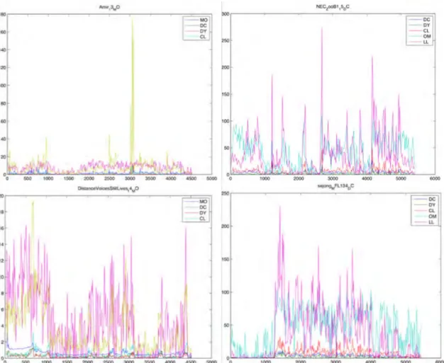
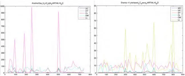
A set of significant graphs are reported in
Figure 3
andFigure 4
.Figure 4 Feature development in time (Robust set)
Two main considerations led our activities.
• Each features is characterized by a specific trend which is more or less relevant in some temporal segments of the video. This aspect provides a preliminary method for automatic distinguish among the set of available features, the most significant feature. For example in
Figure 3
we can observe that in some cases the variation of some feature is almost zero where some other features have significant variations; in some other cases all features vary, but differently.• It is clear in the graphs (
Figure 4
) that the most pronounced variations of the features is visible in the queries of type partial: more than one features have a maximum around the boundaries of the query immersed in dummy. This suggested us the strategy for detect the real query in the PARTIAL, as will be explained in Section 2.4.3.2.4
The proposed method for copy detection
Referring to the system of
Figure 1
the method for copy detection is spitted in four operations blocks: two blocks finalized to the Video Signature generation (feature extraction and feature processing) and two blocks finalized to copy detection testing (filtering and matching).2.4.1
Feature extraction
For each video and query, all possible features are extracted. In our test we considered the Descriptors described in Section 2.2.
This approach can be generalized: for each video and queries, on the basis of the local engine and hence on the local feature extractors, all possible features are extracted along time. For each video and query a vector of feature is generated:
€
F = f
{
1( )
t
,
f
2( )
t
, f
3( )
t
...
}
.2.4.2
Feature processing
The all features extracted need to be formalized according to the MPEG-7 Video Signature above defined. So the feature processing block is in charge to transform the set of feature F in the Video Signature, VSQ for the query and VSV for the video.
So, the basis of the temporal granularity considered (shots, micro-segments, GOP, etc.), each Segment-DS is characterized by a set of Descriptors, where each Descriptor is followed by a weight.
The procedure that determines the temporal segmentation, the suitable descriptors and its weights is very important, and in this respect there are several possibilities. A possible automatic method to define the Segment-DS and the weight has been proposed in Section 2.3.3. Such method is robust but it is time consuming because a pre-processing of all videos on all available features is required. A simpler strategy could consider a predefined temporal segmentation, e.g., GOP based, and could decide to give all the considered descriptors the same weights.
2.4.3
Filtering
Once the VQ has been generated for queries and videos (VSQ and VSV), the query is filtered in
order to separate DIRECT queries from PARTIAL query. As shown in
Figure 3
the features that characterize DIRECT queries do not have significant maximum in time development; on the other hand the PARTIAL queries are characterized by a set of concomitant peaks at the beginning and at the and of the query immersed in the dummy data. Therefore a lateral ranking procedure is performed as follows. First, the internal distance vectors di are computed as:€
d
i, j=
0
j = 1
D
i(
f
i, j, f
i, j−1)
j = 2,
…,N
⎧
⎨
⎪
⎩
⎪
where€
D
i(⋅)
is the suitable distance for the i-th feature€
fi(t) where i=1,…,F (e.g. the EMD for the dominant colors feature). The internal distance vectors are then sorted in decreasing order, thus producing a set of sorted lists
€
si that contain the succession of the indexes of the sorted internal
distance vectors, so that the first element of
€
si is the index of the highest value in
€
di. The lateral
ranking vector r is then computed in each position j by summing the rank of j in each of the F sorted lists
€
si. The position of the 2 minimum values of r are assumed to represent the starting and
ending point of the immersed query.
This approach can be improved using specific techniques for temporal decompositions. For example temporal segmentation in shots could be very useful for the PARTIAL queries in order to refine the obtained results of lateral ranking.
Hence, the filtering block produces the following results:
• if no significant peaks in the features development in time has been detected, the VQQ is
classified as DIRECT and it is passed as a whole to the next block (matching block);
• if significant peaks in the features development in time has been detected, the VQQ is
classified as PARTIAL, it is cleaned by removing the dummy parts and then it is passed to the next block (matching block) with ESPQUERY (Estimated Start Point) and EEPQUERY (Estimated
End Point) [MPEG-VS-08] [MPEG-VS-09]. The duration of the query (EEPQUERY -
ESPQUERY) will be used in the matching block for localization of the query I the original clip.
2.4.4
Matching
Since, both query and video are characterized by a Video Signature, respectively called VSQ and
VSV and store in the databases (
Figure 1
), the VQQ provided by the filtering block is thencompared with the Video Signature of the original clip VQV. Each VQQ and VQV consists of a set
of Descriptors, whose weights and distance measures are known. These information are used for the matching process described following.
• If VSQ and VSV have common Descriptors, these common Descriptors are used to compare the
query with all the videos, with the aim to locate its ESP (Estimated Start Point) in the original clip [MPEG-VS-08] [MPEG-VS-09].
• The weight of each descriptor, if any, is suggested in VSQ and VSV.
The comparison is performed by evaluating the distance between the descriptors associated to the query and the descriptors associated to a sliding window of the same duration in the original video
clip. This distance has been obtained averaging the local distances obtained applying the metric operator. When the sliding window has spanned the whole video clip, we obtain a function which plot the distance between the query and the window of the original video clip, with respect to the temporal position of the window in the video clip. Looking at the local and global minima of this function we can evaluate if the global minimum is in accordance or not with the ground truth (we know the position of each query in the clip) and where the local minima are positioned.
In the implemented algorithm was excessively time consuming, so a faster version has been implemented. This second algorithm is based on centre of mass computation of the Descriptors of the query and of the Descriptors of each segment of the original clips, which is decomposed in a set of equal segments.
The method of the centre of mass consists in a pre-selection of the clip-query pairs that is performed before actually engaging the sliding window approach. First, each clip is chopped into 6 equal segments and for every segment the Descriptors are extracted and the corresponding centre of mass is commutated. During the matching, the centre of mass of each query is computed and compared with the original clips by means of the standard Euclidean distance. A pre-threshold B is finally obtained by taking the value within the population of the previously computed distances correspondent to a specified percentage of the distances histogram (PERCENTAGE). During the matching, the system takes into account all the centre of mass distances relative to the considered query-clip pair.
• If any of the latter is less than B, then the sliding window approach is run and the distance output is computed as usual;
• otherwise, the content of the query and the clip are judged too different and the distance of this pair is not evaluated (but it is nevertheless considered for the threshold computation in the case of the independence).
The pre-selection procedure allows to compute the feature distances for only approximately 4% of the pairs.
3 Performance evaluation of the proposed technology
In this section we present some results of the experimental evaluation, according to the criteria specified in [MPEG-VS-08] [MPEG-VS-09].
With respect of the Descriptors considered in Section 2.2, the experiments have been performed on three visual Descriptors:
• Dominant Color (DC) with 8 colors
• Dominant Luminance (DY) with 4 luminace values • Color Layout (CL).
This features have been extracted for all I-frames of video/query, so we considered a GOP temporal resolution. Besides, we also concentrated on the evaluation of DIRECT and PARTIAL 2 seconds. We trust to present some additional results at the meetings on the others queries DIRECT/PARTIAL 5/10 seconds.
3.1
Independence results
For the computation of the thresholds, this Call for Proposals is evaluated under 3 different durations of the segment to be matched (D), i.e., D=2 seconds, 5 seconds, and 10 seconds.
In the case of partial content matching, the durations D=2 seconds, 5 seconds, and 10 seconds are the minimum durations of the segment to be matched which are given to the algorithm (the algorithm searches for any matching segment longer than these given durations, e.g., segment longer than 2 seconds in case of D=2 seconds), and the total duration of the query clips is 30 seconds. Note that the durations of the original clips are > 3 minutes.
This means that the Call for Proposals is evaluated under 6 different query types independently. The operational settings obtained with our system are exhibited in
Table 3
. We considered two operational points with different centre of mass (PERCENTAGE).Table 3 Threshold from Independence test
DC DY CL
DIRECT 02 (percentage = 1%) 7.13358 1.33022 8.41417 DIRECT 02 (percentage = 5%) 6.12565 0.928964 -
3.2
Robustness results
In this Call for Proposals, a database of original video clips is compared with query clips which are assumed to be derived from the original videos.
For each comparison between the query clip and the original clip, the proposed algorithm is required to output a binary decision:
a) clips are related (i.e., clips contain modified segments of one another), b) clips are not related.
If the query is related, in the case of DIRECT queries the ESP (Estimated Start Point) in the query need to be reported while in the case of PARTIAL queries the ESP (Estimated Start Point) and EST (Estimated End Point) need to be reported for both query and original clip.
The results obtained with our system are reported in
Table 4
.Table 4 Robustness results for DIRECT 02
ATTACK TYPE STRENGTH DC (5%) DY (5%) CL (1%)
Analog VCR Capture Light 14.3% 1% 28,2%
Brightness Change Light 37,2% 3,3% 30%
Camera on Capture Light 0% 0,4 % 0%
Frame Reduction Light 0% 2% 0%
Interlaced Progressive Conversion Light 24,6% 3,7% 43,8%
Monochrome Light 7,2% 1,1% 6,3%
Resolution Reduction Light 26% 1,8% 43,9%
Severe Compression Light 26% 2,4% 35,6%
Text Logo Overlay Light 15% 0,5% 36,9%
Table 5 Robustness results for PARTIAL 02
ATTACK TYPE STRENGTH DC (1%) DY (1%) CL (1%)
Analog VCR Capture Light 0,9% 0% 2,4%
Brightness Change Light 4% 0% 1,1%
Camera on Capture Light 0% 0% 0%
Frame Reduction Light 0% 0% 0%
Interlaced Progressive Conversion Light in progress in progress in progress
Monochrome Light 0.7% 0% 0%
Resolution Reduction Light 1,5% 0% 2%
Severe Compression Light in progress in progress in progress
Text Logo Overlay Light 0,5% 0% 0.9%
Some considerations can deducted from the results reported in
Table 4
andTable 5
. • Obviously different features provide different performance.• More interesting is that the features act differently from attack to attack; for instance, DC provides better performance in Brightness Change than CL while CL provides better performance in Analog VCR Capture than.
3.3
Performance measures
3.3.1
Video Signature size
Let’s suppose to have a clip of 1 second duration characterized by the proposed descriptors in Section 2.2. The size of such clip can be estimated considering the following approximate items:
• Mpeg 7 description (text): less than 0.1 Kbyte/sec • Dominant Color (text): ~ 0.01 kbyte/sec
• Dominant Luminance: ~ 0.003 kbyte/sec • Color Layout (text): ~ 0.01 kbyte/sec • Luminance Layout: ~ 0.005 kbyte/sec
• Motion Map and Direction (binary): ~ 0.4 kbyte/sec
The sum of these items provides the size of 1 second clip considered, that is approximately 0.528 kbyte/sec, which is much less than 30 kbyte/sec.
In this computation the temporal segmentation at different levels has not been considered because it is negligible: the temporal decomposition is useful only when it is provided at higher level descriptions, where the byte occupancy is very small within the whole considered video.
3.3.2
Extraction and Matching Complexity
The specification of the computer used for extraction and matching is reported in
Table 6
. Extraction and matching speed for the considered feature (DC, DY, CL and HD) PARTIAL 02 is reported inTable 7
.Table 6 PC specification
CPU name Dual Core Xeon x 2
CPU speed (GHz) 3GHz/processor
Operating System MAC OSX 10.4.11 – Tiger
Memory (GB) 9GB
Table 7 PC Extraction and Matching speed
PARTIAL 02 Extraction 60 sec/8 Descriptors
Matching CL: ~0.2 match/sec
CY: ~1 match/sec DC: ~1,8 match/sec
Conclusions
In this document we have presented and partially evaluated this video signature system, proposed by SCL-DEA University of Brescia (Italy).
The studies and the results are based on multi-features technology. The preliminary evaluations and the results show that the features change relevance in time development and with the attack type.
References
[MPEG-VS-08] MPEG Video Sub-Group, “Updated Call for Proposals on Video Signature Tools”, ISO/IEC JTC1/SC29/WG11 MPEG 2008/N10155, October 2008, Busan, Korea.
[MPEG-VS-09] MPEG Video Sub-Group, “Description of Core Experiments in Video Signature Description”, ISO/IEC JTC1/SC29/WG11 MPEG 2009/N10345, February 2009, Lausanne, CH. [MPEG7-01] “Text of ISO/IEC 15938-3/FDIS Information technology – Multimedia content description interface – Part 3 Visual”, ISO/IEC/JTC1/SC29/WG11 Doc. N4358, July 2001, Sydney, Australia.
[MPEG7-02] “Text of ISO/IEC 15938-5/FDIS Information technology – Multimedia content description interface – Part 5 Multimedia Description Scheme”, ISO/IEC/JTC1/SC29/WG11 Doc. N4358, July 2001, Sydney, Australia.
[MPEG7-XM-01] Akio Yamada, Mark Pickering, Sylvie Jeannin, Leszek Cieplinski, Jens Rainer Ohm, Munchurl Kim, “MPEG-7 Visual part of eXperimentation Model Version 9.0”, ISO/IEC JTC1/SC29/WG11/N3914, January 2001, Pisa, Italy.
[MPEG7-book-02] B.S. Manjunath, Philippe Salembier, and Thomas Sikora, “Introduction to MPEG-7 – Multimedia Content Description Interface”, John Wiley & Sons, LTD, 2002.
[CTD-2001] B.S. Manjunath, Jens-Rainer Ohm, Vinod V. Vasudevan, Akio Yamada, “Color and Texture Descriptors”, IEEE Trans. On CSVT, pp. 703-715, Vol. 11, No. 6, June 2001.
[MD-2001] Sylvie Jeannin, Ajay Divakaran, “MPEG-7 Visual Motion Descriptors”, IEEE Trans. On CSVT, pp. 720-724,Vol. 11, No. 6, June 2001.
[BXL-2005] S. Benini, Li-Qun Xu, R. Leonardi, “Using Lateral Ranking for Motion-Based Video Shot Retrieval and Dynamic Content Characterization”, Proc. CBMI-2005, Riga, Latvia, June 21-23, 2005.
[MAM-2002] Wei Zeng, Wen Gao, Bedin Zhao, “Video Indexing by Motion Activity Maps”, Proc. ICIP-2002, Rochester, NY, USA, Sept. 2002.
[EMD-1998] Yossi Rubner, Carlo Tomasi, Leonidas J. Guibas, “A Metric for Distributions with Applications to Image Databases”, Proc. IEEE ICCV, Bombay, India, 1998.
[OM-2007] Julien Law-To, L. Chen, A. Joly, Ivan Laptev, Olivier Buisson, Valérie Gouet-Brunetand, and Nozha Boujemaa “Video copy detection: a comparative study” Proc. ACM Multimedia, Augsburg, Germany, September, 2007