UNIVERSITY
OF TRENTO
DIPARTIMENTO DI INGEGNERIA E SCIENZA DELL’INFORMAZIONE
38123 Povo – Trento (Italy), Via Sommarive 14
http://www.disi.unitn.it
A DVBH/GSM/UMTS PLANAR ANTENNA FOR MULTIMODE
WIRELESS DEVICES
L. Lizzi, E. Viani, E. Zeni, and A. Massa
January 2011
1
A DVBH/GSM/UMTS Planar Antenna for
Multimode Wireless Devices
Leonardo Lizzi, Federico Viani, Edoardo Zeni, and Andrea Massa,
Abstract
In this letter, the prototype of a planar antenna working in three different frequency bands and suitable to be integrated in multimode wireless devices is described. The antenna is fed by a single RF port without any matching circuit and it operates in a DVBH channel and at GSM and UMTS frequency bands. Its dimension is of 0.15λ at the lower frequency band. The effectiveness and feasibility of the proposed antenna is assessed by means of both simulations and measurements.
Index Terms
Fractal antennas, multimode, multiband, DVBH, GSM, UMTS.
I. INTRODUCTION
Today’s competitive market requires multimode capabilities for each wireless device because of the rising demand for new higher-speed mobile broadband and multifunction applications. On the other hand, mobile handsets are characterized by smaller and smaller sizes and reduced weights thanks to the progress of modern integrating circuit technology and following the users’ needs. To this end, the design of suitable RF front-ends plays a very important and critical role.
Concerning the dimension requirement, the use of conventional monopole-like antennas is generally avoided because of their relatively large sizes when compared to that of the device itself [1]. A more effective solution considers microstrip planar radiators, which are more easily adaptable to the shape of the handset at hand. However, standard half-wavelength microstrip antennas at the operating frequencies of modern mobile applications (e.g., DVBH) turn out to be still too large for an efficient integration into a miniaturized mobile device.
As regards to the multiband operation [2], new strategies are under development for integrating multiple functionalities and reducing, at the same time, both costs and complexity. Such a task is usually addressed by using duplexers along with band-pass filters in the receiving and transmitting paths. Unfortunately, such a solution needs Surface Acoustic Wave (SAW) filters and Low Noise Amplifiers (LNAs) with a non-negligible increase of the costs and of the dimensions. Some attempts to minimize the occupied space have been done by integrating on-chip the LNA. Nevertheless, further efforts are devoted to avoid the use of external filters in order to reduce the number of components and to simplify the board layout. Towards this end, a possible solution consists in moving the frequency selectivity functions “closer” to the antenna. In other words, this means that the radiating system must show an adequate impedance matching within each band of operation without external components.
Following such a guideline, this letter describes a three-band fractal antenna synthesized by exploiting the optimization approach proposed in [3][4] and aimed at minimizing the radiator dimensions as well as at obtaining a multi-band behavior. The result is a single radiating structure that resonates at three different bands and suitable for an integration in board layouts. As a matter of fact, it should be pointed out that fractal shaped antennas have proved to be effective not only for miniaturization purposes [5], but also to achieve a multi-band behavior [6]-[9] since their radiation properties are determined by the electrodynamic properties of fractal shapes.
Authors are with the Department of Information Engineering and Computer Science, University of Trento, Trento, Italy (e-mail: [email protected], {leonardo.lizzi, federico.viani, edoardo.zeni}@disi.unitn.it).
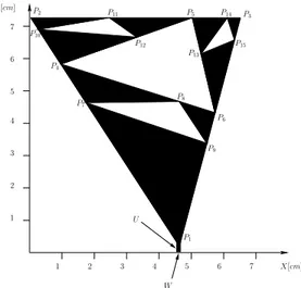
1 2 3 4 1 2 3 4 5 6 7 X[cm] 5 6 7 Y[cm] P1 P2 P6 P8 P9 U P5 P11 P14 P3 P15 W P7 P4 P12 P13 P10
Fig. 1. Geometry of the multimode three-band antenna.
The outline of this letter is as follows. Section II describes the antenna geometry and it summarizes some details on the design procedure. The efficiency and reliability of the synthesized antenna are assessed in Sect. III by means of both numerical and experimental results. Finally, some concluding remarks are given in Sect. IV.
II. ANTENNADESIGN
The geometry of the antenna is shown in Fig. 1. As it can be observed, the reference shape is a planar Sierpinski pre-fractal where three iteration stages (s = 0, 1, 2) have been considered to set three different resonances [7]. From a geometric point of view, the antenna structure is uniquely defined by the following descriptors
χ ={U, W, Pi= (Xi, Yi) ;i = 1, ..., 15} (1)
where U and W are the length and the width of the input section, respectively. Moreover, (Xi, Yi)i = 1, ..., 15 are the
coordinates of the vertexes of the void triangles in Fig. 1 descriptive of the antenna geometry. Since the antenna is required to be compact (maximum size 8× 8 [cm2]
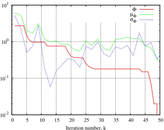
) and to simultaneously operate at three different frequency bands, the user-defined constraints require Voltage Standing Wave Ratio (VSWR) values lower than 2.5 at the center of each frequency band and smaller than 3.0 along the whole bandwidths, respectively. As regards to the synthesis process, the final antenna shape has been then determined by applying the optimization procedure proposed in [3][4]. Such an iterative technique integrates an electromagnetic simulator based on the Method-of-Moment (MoM) [10] and a Particle Swarm Optimizer (PSO) [11][12] in order to find an antenna configuration fitting a set of user-defined constraints on the size and the impedance matching behavior. More in detail, a swarm of R = 5 particles has been randomly initialized and iteratively updated according to the P SO logic until a solution fitting the user-defined requirements has been found. In Fig. 2, the behavior of the cost function Φ over the iterations (kconv= 50) is given. For completeness, the cost function mean value µΦ as well as the
standard deviation σΦ are reported. As regards to the optimization results, Figure 3 shows a scatter plot of the V SW R values
at kconv. Each point of the plot indicates the simulated V SW R value at the center of a frequency band in correspondence
with a swarm solution. As it can be observed, all the trial solutions at the convergence meet the performance requirements in the GSM and U M T S bands, but only one representative point (i.e., only one trial solution) falls below V SW R = 2.5 in the
DV BH band.
Taking into account the constraints on the shape and electric behavior of the device at hand, the following values of the antenna descriptors have been identified at the end of the PSO-based optimization process. The dimensions of the input section turns out to be U = 0.28 mm and W = 0.12 mm. Moreover, the coordinates of the control points (in [cm]) result:
3 10-2 10-1 100 101 0 5 10 15 20 25 30 35 40 45 50 Iteration number, k Φ µΦ σΦ
Fig. 2. Behaviors of the cost function statistics during the iterative P SO optimization.
1 1.5 2 2.5 3 3.5 4 4.5 5 2100 1850 610 VSWR Frequency [MHz]
Fig. 3. Simulated VSWR values, at the center of each frequency band, for the trial solutions at the convergence.
P1 = (4.5, 0.1), P2 = (0.0, 7.4), P3 = (6.6, 7.4), P4 = (1.0, 5.8), P5 = (5.2, 7.4), P6 = (5.8, 4.3), P7 = (1.8, 4.7),
P8 = (4.7, 4.7), P9 = (5.5, 3.4), P10 = (0.3, 7.0), P11 = (2.5, 7.4), P12 = (3.3, 6.7), P13 = (5.4, 6.2), P14 = (6.2, 7.4),
and P15= (6.4, 6.7). As a macroscopic result, the antenna prototype covers an area of 6.6× 7.4 cm 2
. More specifically, the maximum linear dimension of the antenna at the highest wavelength of operation is equal to 0.15λ with a reduction of more than 40% with respect to the corresponding quarter-wave resonant monopole.
III. NUMERICAL ANDEXPERIMENTALRESULTS
In this section, some numerical and experimental results aimed at validating the efficiency and reliability of the proposed antenna are shown. To perform the experimental measurements, a prototype of the antenna has been built (Fig. 4) on a planar dielectric substrate (Arlon: thickness h = 0.8 mm, relative permittivity εr = 3.38, tan δ = 0.002 at f = 10 GHz). The
Wireless Frequency Band VSWR VSWR
Service [M Hz] Centerband on Band
DVBH 606 ÷ 614 2.4 2.5
GSM 1800 ÷ 1900 1.2 1.8
UMTS 2000 ÷ 2200 1.3 1.9
TABLE I
Fig. 4. Antenna Prototype. 1 2 3 4 5 6 7 8 9 10 2500 2200 1700 1200 700 200 VSWR Frequency [MHz] Simulated Measured
Fig. 5. Simulated and measured VSWR values.
prototype, fed by a single 50 Ω RF port connected to the antenna structure in P1 and mounted on a metallic ground plane, has
been used to collect both VSWR and radiation patterns measurements in an anechoic chamber.
The electric performances of the synthesized antenna are summarized in Tab. I. As far as the impedance matching is concerned, Figure 5 shows a comparison between measured and simulated VSWR values. As expected, the antenna resonances are located at the center of a DVBH channel (f0DV BH = 610M Hz), in the higher GSM band (f
GSM 1800
0 = 1850M Hz),
and in correspondence with the UMTS band (f0U M T S= 2100M Hz). Besides the good agreement between the two plots (i.e.,
numerical and measured values), the antenna shows a good impedance matching in the GSM band (1.2≤ V SW RGSM 1800 simulated≤
1.8, 1.6≤ V SW RGSM 1800
measured ≤ 2.1) and in the UMTS band (1.3 ≤ V SW R U M T S
simulated ≤ 1.9, 1.3 ≤ V SW R U M T S
measured ≤ 1.8).
On the other hand, an acceptable matching has been also obtained at the lowest working frequency devoted to the reception of a DVBH channel (2.4≤ V SW RDV BH
simulated≤ 2.5, 2.2 ≤ V SW R DV BH
measured≤ 2.3). Higher VSWR values in this latter band are
mainly caused by the constraint on the antenna size. As a matter of fact, a V SW R value below 2 : 1 can be easily reached by relaxing the miniaturization requirement (e.g., from 8× 8 [cm2]
to 9.5.× 9.5 [cm2]
).
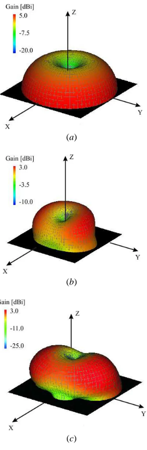
As regards to the radiation properties, Figure 6 shows the simulated three-dimensional gain patterns computed at the center of each frequency band. As it can be observed, the radiation pattern is monopole-like at the lowest frequency [Fig. 6(a)], while some variations occur when the working frequency increases [Fig. 6(b)-(c)]. As a matter of fact, the antenna tends to work like a half-wave monopole in the highest frequency bands. Such a behavior is further pointed out by the appearance of additional lobes in the radiation diagram. Nevertheless, the omnidirectional behavior along the horizontal plane makes the antenna suitable for mobile wireless devices.
5
(a)
(b)
(c)
Fig. 6. Simulated 3D radiation patterns - (a) Total gain at fDV BH
0 = 610 M Hz; (b) Total gain at f GSM 1800
0 = 1850 M Hz; (c) Total gain at
fU M T S
0 = 2100 M Hz.
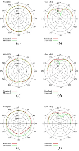
For completeness, the numerical values are compared with the measurements at the horizontal plane (θ = 90◦) and at the
vertical one (φ = 90◦) (Fig. 7). Once again, measurements and simulations turn out to be in good agreement although some
difference are present in the UMTS band [Fig. 7(e)-(f )]. They can be ascribed to the non-ideal behavior of the measurement environment at higher frequencies.
Finally, the simulated behaviors of the surface currents are shown in Fig. 8. As expected and because of the multi-band operation, the plots at the different frequencies significantly differ. Moreover, the variations of the surface current along the longitudinal direction show a trend similar to that of a quarter-wave monopole in the DVBH band [Fig. 8(a)], while they turn out to be close to that of a half-wave monopole at the higher working frequencies [Fig. 8(b)-(c)].
10 0 -10 -20 -30 Gain [dBi] 90 60 30 0 330 310 270 240 210 180 150 120 Simulated Measured 10 0 -10 -20 -30 Gain [dBi] 90 60 30 0 330 310 270 240 210 180 150 120 Simulated Measured (a) (b) 10 0 -10 -20 -30 Gain [dBi] 90 60 30 0 330 310 270 240 210 180 150 120 Simulated Measured 10 0 -10 -20 -30 Gain [dBi] 90 60 30 0 330 310 270 240 210 180 150 120 Simulated Measured (c) (d) 10 0 -10 -20 -30 Gain [dBi] 90 60 30 0 330 310 270 240 210 180 150 120 Simulated Measured 10 0 -10 -20 -30 Gain [dBi] 90 60 30 0 330 310 270 240 210 180 150 120 Simulated Measured (e) (f )
Fig. 7. Simulated and measured radiation patterns - (a) Horizontal plane (θ= 90◦) at fDV BH
0 = 610 M Hz; (b) Vertical plane (φ = 90◦) at f DV BH 0 = 610 M Hz; (c) Horizontal plane (θ = 90◦) at fGSM 1800 0 = 1850 M Hz; (d) Vertical plane (φ = 90◦) at f GSM 1800
0 = 1850 M Hz; (e) Horizontal plane
(θ= 90◦) at fU M T S
0 = 2100 M Hz; (f ) Vertical plane (φ = 90◦) at f U M T S
0 = 2100 M Hz.
IV. CONCLUSIONS
A three-band planar antenna for DVBH, GSM, and UMTS wireless services has been described. The antenna exhibits reduced dimensions and an acceptable impedance matching in the working frequency bands. The antenna performances have been numerically and experimentally assessed. The obtained results confirm the reliability of the numerical synthesis as well as the feasibility and effectiveness of the proposed solution for multifunction wireless devices.
REFERENCES
[1] Y.-X. Guo, M. Y. W. Chia, and Z. Nn. Chen, “Miniature built-in multiband antennas for mobile handsets,” IEEE Trans. Antennas Propagat., vol. 52, no. 8, pp. 1936-1944, 2004.
[2] M. Martinez-Vazquez, O. Litschke, M. Geissler, D. Heberling, A. M. Martinez-Gonzalez, and D. Sanchez-Hernandez, “Integrated planar multiband antennas for personal communication handsets,” IEEE Trans. Antennas Propagat., vol 54, no. 2, pp. 384-391, 2006.
[3] R. Azaro, G. Boato, M. Donelli, and A. Massa, “Design of a prefractal monopolar anenna for 3.4-3.6 GHz Wi-Max band portable devices,” IEEE
Antennas Wireless Propag. Lett., vol. 5, pp. 116-119, 2006.
[4] R. Azaro, F. De Natale, M. Donelli, E. Zeni, and A. Massa, “Synthesis of a prefractal dual-band monopolar antenna for GPS applications,” IEEE
Antennas Wireless Propag. Lett., vol. 5, no. 1, pp. 361-364, Dec. 2006.
[5] J. Gianvittorio and Y. Rahmat-Samii, “Fractal antennas: a novel antenna miniaturization technique, and applications,” IEEE Antennas Propagat. Mag., vol. 44, no. 1, pp. 20-36, Feb. 2002.
7
(a)
(b)
(c)
Fig. 8. Simulated surface currents at (a) f0DV BH= 610 M Hz, (b) f
GSM 1800
0 = 1850 M Hz, and (c) f U M T S
0 = 2100 M Hz.
[6] D. H. Werner, P. L. Werner, and K. H. Church, “Genetically engineered multiband fractal antennas,” Electron. Lett., vol. 37, pp. 1150-1151, 2001.
[7] C. Puente-Baliarda, J. Romeu, R. Pous, and A. Cardama, “On the behavior of the Sierpinski multiband fractal antenna,” IEEE Trans. Antennas Propagat., vol. 46, no. 4, pp. 517-524, 1998.
[8] D. H. Werner and S. Ganguly, "An overview of fractal antenna engineering research," IEEE Antennas Propag. Mag., vol. 45, no. 1, pp. 38-57, Feb. 2003.
[9] D. H. Werner and R. Mittra, Frontiers in Electromagnetics. Piscataway, NJ: IEEE Press, 2000.
[10] R. F. Harrington, Field Computation by Moment Methods. Malabar, FL: Robert E. Krieger Publishing Co., 1987.
[11] J. Robinson and Y. Rahmat-Samii, “Particle swarm optimization in electromagnetics,” IEEE Trans. Antennas Propag., vol. 52, no. 2, pp. 397-407, Feb. 2004.
[12] D. W. Boeringer and D. H. Werner, "Particle swarm optimization versus genetic algorithms for phased arrays synthesis," IEEE Trans. Antennas Propag., vol. 52, no. 3, pp. 771-779, Mar. 2004.
![Fig. 4. Antenna Prototype. 1 2 3 4 5 6 7 8 9 10 2500220017001200700200VSWR Frequency [MHz] SimulatedMeasured](https://thumb-eu.123doks.com/thumbv2/123dokorg/2945258.22703/6.918.328.590.78.317/fig-antenna-prototype-vswr-frequency-mhz-simulatedmeasured.webp)