(will be inserted by the editor)
A4WSN: An Architecture-driven Modelling Platform for
Analysing and Developing WSNs
Ivano Malavolta · Leonardo Mostarda · Henry Muccini · Enver Ever · Krishna Doddapaneni · Orhan Gemikonakli
Received: date / Accepted: date
Abstract This paper proposes A4WSN, an architecture-driven modelling platform for the development and the analysis of Wireless Sensor Networks (WSNs).
A WSN consists of spatially distributed sensor nodes that cooperate in order to accomplish a specific task. Sensor nodes are cheap, small, and battery-powered de-vices with limited processing capabilities and memory. WSNs are mostly developed directly on the top of the operating system. They are tied to the hardware configura-tion of the sensor nodes and their design and implementaconfigura-tion can require cooperaconfigura-tion with a myriad of system stakeholders with different backgrounds.
WSNs peculiarities and current development practices bring a number of chal-lenges, ranging from hardware-software coupling, limited reuse, late WSNs quality property assessment. As a way to overcome a number of existing limitations, this study presents a multi-view modelling approach that supports the development and analysis of WSNs. The framework uses different models to describe the software architecture, hardware configuration, and physical deployment of a WSN. A4WSN
Ivano Malavolta
Gran Sasso Science Institute, L’Aquila, Italy E-mail: [email protected] Leonardo Mostarda
Computer Science Department, University of Camerino, Camerino, Italy E-mail: [email protected]
Henry Muccini
Computer Science and Mathematics, University of L’Aquila, Italy E-mail: [email protected]
Enver Ever
Computer Engineering, Middle East Technical University, Northern Cyprus, Turkey E-mail: [email protected]
Krishna Doddapaneni
Computer Communications Engineering, Middlesex University, UK E-mail: [email protected] Orhan Gemikonakli
allows engineers to perform analysis and code generation in earlier stages of the WSN development life cycle. The A4WSN platform can be extended with third-party plu-gins realizing additional analysis or code generation engines.
We provide evidence of the applicability of the proposed platform by develop-ing PlaceLife, an A4WSN plugin for estimatdevelop-ing the WSN life time by takdevelop-ing var-ious physical obstacles in the WSN deployment environment into account. In turn, PlaceLife has been applied on a real-world case study in the health-care domain as a running example. A case study based on home automation is presented as well. Keywords MDE · Software Engineering · Software Architecture · Wireless Sensor Networks
1 Introduction
A recent study predicted that in 2020 there will be 50 billion devices connected to the Internet (seven times the worlds population) [20]. These devices are not only smartphone and tablets, but also things which are able to perform various operations, such as sensing data, actuating on the external environment, and so on. With this per-spective, Wireless Sensor Networks (WSNs) are getting mainstream in a wide variety of applications and systems; possible applications include environment monitoring, energy metering, smart cities, health care and intelligent houses [55].
Wireless sensor networks are composed of low-data rate, low-cost and battery-operated wireless components called sensor nodes. A sensor node is a small digital device with communication, sensing, and limited processing capabilities. WSNs can range from small scale networks such as body sensor networks with few nodes [69], to large scale networks such as smart city applications with thousands of sensor nodes [23].
Despite the increasing usage of WSNs in modern applications, their development is still plagued by the following issues: (i) development is still performed directly on the top of the operating systems and relies on individuals hard-earned programming skills across all levels of the communication stack (e.g., application, routing, data link levels, etc.) [43]; (ii) WSN engineers must address challenging extra-functional requirements such as performance, security, energy consumption, with poor support for early testing, debugging, and simulation of WSNs in an integrated fashion [30]; (iii) in order to achieve the demanded high level of efficiency, the software of a WSN application is tied to specific hardware platforms, thus hampering the reuse of source code and software components across different projects or organizations [43]; (iv) due to the intrinsic multidisciplinary nature of the WSN problem space, WSN engineers must continuously collaborate with a high number of system stakeholders (e.g., WSN users, application domain experts, hardware designers, and software developers) with different background and training [55].
As a possible solution to the above mentioned issues, the WSN community is becoming aware of the need of using software engineering approaches in order to support the design, analysis, simulation and implementation of WSNs [68, 51].
This research contributes with a novel modelling and analysis platform to support an architecture-driven development of WSNs. The platform is called A4WSN1 and
is based on a multi-view architectural approach [33] based on three modelling lan-guages to describe a WSN from different viewpoints: (i) software components and their interactions, (ii) the low-level and hardware specification of sensor nodes, and (iii) the physical environment where sensor nodes are deployed, separately. Model-driven engineering (MDE) techniques and tools are used to realise the modelling framework through metamodelling, model weaving and model transformation. The modelling framework is supported by a programming framework that enables the im-plementation of analysis and code generation plugins by third party developers; they can be employed to assess and analyse the architectural design decisions and used to generate executable code, respectively.
The whole A4WSN platform is realised by exploiting advanced Model-driven Engineering (MDE) techniques, such as metamodelling, model weaving and model transformation. MDE allows us to define the modelling languages of A4WSN in a seamless and well-disciplined manner, and to realise the A4WSN programming framework so that it supports extensibility and customisation by design. We pro-vide epro-vidence on the applicability of the proposed modelling approach and on the extensibility of its programming framework by developing a A4WSN plugin called PlaceLife. Placelife analyses A4WSN models of a WSN and automatically assesses the life time of the network.
PlaceLife uses the A4WSN physical environment model that includes physi-cal objects and material, thus providing an accurate WSN lifetime estimation. The PlaceLifeplugin has been applied onto a realistic case study in the home automation application domain. The scenarios that can be considered using A4WSN are more realistic compared to existing simulation tools for WSNs, since the existing tools consider simplified models of the environment (e.g., a free space model) due to the limitations mentioned above. In a previous work [19] we made the first exploration for the feasibility of the modelling and analysis platform, with special emphasis on energy consumption analysis. In that work, the used modelling languages and the programming framework were in an incubation phase. The main contributions of this paper can be summarised as follows:
– a multi-view modelling platform for engineering WSNs is presented in details (including a specification of the software architecture, low-level and hardware specification, and physical environment);
– a programming framework is provided which enables the development of plugins realising new code generation and analysis engines;
– the A4WSN prototype tool2realising the approach presented has been fully
im-plemented; it is based on the Eclipse platform and can be integrated with other MDE technologies already available in the Eclipse community;
– the PlaceLife plugin for the prediction of the life time of a WSN is presented, where the physical environment (together with other factors) is also taken into account unlike the existing studies.
1 It stands for Architecting platform for (4) Wireless Sensor Networks 2 A4WSN prototype: http://a4wsn.di.univaq.it
The rest of this paper is organised as follows. Section 2 provides background information on WSNs, and the motivational example used throughout the paper. Sec-tion 3 provides an overview of the A4WSN platform. SecSec-tion 4 describes the pro-posed modelling languages for WSNs, while Section 5 presents the programming framework. Section 6 presents the technologies we use to implement the A4WSN platform. Section 7 focusses on the PlaceLife analysis plugin. Finally, Section 8 presents related work, while the paper concludes in Section 9.
2 Background and Motivational Example
This section provides a background on wireless sensor networks (Section 2.1), con-siderations to motivate the need of our approach (Section 2.2), and introduces the case study used throughout the paper (Section 2.3).
2.1 Background on Wireless Sensor Networks
Wireless Sensor Networks (WSN) consist of spatially distributed sensors that cooper-ate to accomplish some tasks. Sensors are small battery-powered devices with limited processing capabilities and memory. In the current state of the art, WSN nodes pro-cessor frequencies range from 4Mhz to 32 Mhz, whereas typical amounts of memory range from 2 Kb to 512 Kb [43]. They can be easily deployed to monitor differ-ent environmdiffer-ental parameters such as temperature, movemdiffer-ent, sound and pollution. Sensors can be distributed on roads, vehicles, hospitals, buildings, people and enable different applications such as medical services, battlefield operations, crisis response, disaster relief and environmental monitoring.
WSNs can be of the type event-driven or continuous. Event-driven WSNs re-port data to the base station only when certain events occur. For instance, intrusion and fire detection are examples of applications that are implemented by using event-driven WSNs. Continuous WSNs report data to the base station at regular intervals. For instance patient monitoring and temperature control are examples of applications that are implemented by using continuous WSNs. In its most common configura-tion, sensors communicate the sensed information to the base station BS. This can be achieved by using single-hop or multi-hop topology. When single-hop topology is considered, the nodes communicate with the BS directly whereas in multi-hop, some of the nodes may act as intermediate routers which are responsible for forwarding the information from other nodes besides the usual sensing responsibility.
The unique characteristics of WSNs introduce new challenges [63] in different fields such as programming, security and software engineering. Researchers need to face limited sensor resources in terms of computation capabilities and memory as well as the limited life time of the sensors.
Fig. 1 Typical Architecture of a WSN Application
2.2 The WSN challenges and A4WSN solutions
The issues outlined in Section 1 bring a number of WSN design and development challenges. In the following some of the most relevant challenges which can be solved by abstraction and modelling are described. A summary on how the A4WSN frame-work addresses them is also presented in Section 3.
Abstracting implementation details into a design view:the development of a WSN application requires skills across all levels of the communication stack. A WSN ap-plication developer has to be knowledgable on software programming as well as all the layers of the ISO/OSI reference model that is from physical to application layers. Beside the need of programming abstraction, it is well-accepted the need of abstract-ing an implementation view into an architectural design. As remarked in [51], ”end users require high-level abstractions that simplify the configuration of the WSN at large, possibly allowing one to define its software architecture based on pre-canned components”. Abstraction is fundamental for future WSN development, since sen-sors and WSNs in general are becoming important components in pervasive com-puting, and mobile systems, with new types of stakeholders (e.g., mobile systems engineers, developers) and reduced domain-specific technical skills. Under this per-spective, approaches for abstracting the implementation details from the underlying hardware and physical infrastructure are strongly advised [43, 10]. However, when current practices on WSNs are considered, it is quite evident the lack of engineering methods and techniques to manage these challenges. Some initial effort has been con-ducted for architecting WSNs [37, 28], and this paper goes along that line providing more advanced solutions. A thorough comparison with related work is provided in Section 8.
Increase reuse:state of the art approaches mostly mix together software, hardware, and networking perspectives during the coding or design phase. Hardware and soft-ware components are locked and tied down to specific type of nodes, thus hampering the reuse of source code and software components across different projects or orga-nizations [43].
Early WSNs quality property assessment:in traditional implementation-specific ap-proaches engineers might afford to take structural and behavioural decisions at de-ployment time. However, in WSN development it is important to take those sensible decisions as early as possible, enabling the earlier, predictive, analysis of both func-tional and extra funcfunc-tional properties. This possibility becomes especially valuable in all those cases where the sensor nodes cannot be easily accessed once deployed (e.g., WSN nodes embedded into concrete walls or WSNs deployed in hostile envi-ronments).
In order to address the aforementioned challenges we developed A4WSN, an architecture modelling platform that uses different models for specifying WSNs. It provides a design view of the system, and hides low-level details and complexities. A4WSN, being a multi-view approach including different models which cover dif-ferent concerns, increases separation of concerns favouring the possibility to reuse software and hardware components across projects and organisations. A4WSN en-ables model-based analysis techniques and favour the earlier, predictive, analysis of both functional and extra functional properties.
2.3 The health care system case study
In this paper we will use the health case system case study as running example in order to help the reader in promptly understanding the main concepts and design decisions we took when engineering the A4WSN modelling languages. A case study based on home automation is also presented in order to show the effectiveness of the architectural approach and the PlaceLife plugin.
Recent technological advancements in WSNs have opened up new prospects for a variety of applications, including healthcare systems [36, 5, 62]. WSN implemen-tations on pervasive computing based health care systems avoid various limiimplemen-tations and drawbacks associated with the wired sensors providing a better-quality of care, quicker diagnosis, more intense collection of information (can be employed for sta-tistical analysis) and at the same time keeping the cost and resource utilisation to minimal. Monitoring facilities introduced by using WSNs are particularly useful for early detection and diagnosis of emergency conditions, as well as keeping track of the diseases for patients. WSN based health care systems are also useful for provid-ing a variety of health related services for people with various degrees of cognitive and physical disabilities [4].
In the context described above, our case study (graphically illustrated in Figure 2) represents the concept of an in-hospital WSN that allows the personnel of the hospital to monitor patients’ vital sign data with the help of pulse-oximeters. Our
Fig. 2 Hospital scenario considered: i) the central component represents the monitoring station, ii) a pulse-oximeter is included in each room around the central one.
monitoring system consists of two types of nodes: a monitoring station and seven oximeter nodes, forming a star-network. Each pulse-oximeter monitors the patient continuously and a measurement is sent to the monitoring station every three seconds. In case the oximeter reads a value other than a defined threshold, an alert message is sent to the monitoring system, and the system goes into a warning mode in which sensor readings are sent to the monitoring station more frequently (i.e., once every 200 milliseconds), hence facilitating continuous monitoring of patients and allowing real-time responses in case of emergency conditions.
3 Overview of the Platform
In this section we provide an overview of the A4WSN platform. The main goal of our research is to take advantage of Model-Driven Engineering (MDE) techniques to support an architecture-driven development and analysis of wireless sensor net-works. As shown in Figure 3, the A4WSN platform is composed of two main parts: a modelling environment for describing the architecture of a WSN and a programming framework.
The modelling environment exposes three modelling languages for describing specific architectural views of a wireless sensor network: the Software Architecture Modelling Language for WSN(SAML), the Node Modeling Language (NODEML), and the Environment Modelling Language (ENVML). In the following we will de-scribe the rationale that drove us to propose each modelling language. The SAML language focuses on the application layer of the WSN. It is used to break down the application into a set of software entities (e.g., components), to show how they re-late to each other, to better reason on their distribution throughout the network, and to reason on the business logic of the WSN. The NODEML language concerns all the low-level aspects underneath the application layer of the WSN. In this context, stakeholders reason about routing protocols, middleware, hardware configuration of
Fig. 3 Overview of the A4WSN platform
the nodes, etc. The ENVML language is about the site in the real world where the WSN will be deployed. This viewpoint could be specially useful for developers and system engineers when they have to reason about the network topology, the presence of possible physical obstacles (e.g., walls, trees) within the network deployment area, and so on.
In order to provide a useful instrument for modelling WSNs, we identified the sys-tem concerns which are held by engineers and developers while designing a WSN. This set of concerns is based on our experience in the field of WSN development and on some informal investigation we performed on how expert engineers and develop-ers have worked on previous WSN projects. The resulting set of system concerns in the domain of WSN can be summarised as:
– Energy Consumption concerns how much power is consumed by the applica-tion running on the nodes with respect to the used batteries or harvested energy sources. It is a crucial factor that constrains the networks life time for the WSN mission [19].
– Dependability is a generic attribute to describe “the trustworthiness of a com-puting system which allows reliance to be justifiably placed on the service it de-livers”. Dependability includes attributes such as reliability, availability, safety, security as special cases3.
– Coverage represents how well an area is monitored or tracked by sensors [29]. – Networking and Communication represent various networking aspects which may
affect the WSN. Example of the issues which are related to this specific stake-holder comprise: routing protocols, MAC protocols, usage of a specific commu-nication middleware, connectivity of the network, etc.
– Performance deals with all performance-related aspects of the WSN, such as throughput, latency, response times, nodes utilisation, etc.
– Data Collection concerns data structures and how data is collected, managed and transformed by the various nodes within the WSN.
We designed the proposed modelling languages so that they can frame all the above listed concerns. The three proposed modelling languages are linked together via two auxiliary modelling languages in order to create a combined software, nodes, and environmental view of a WSN. These languages are called Mapping Modelling Language (MAPML) and Deployment Modelling Language (DEPML), and they link together SAML to NODEML and NODEML to ENVML, respectively. More specif-ically, MAPML links are used for assigning software components to the correspond-ing hardware node configuration they will be executed on. Whereas, DEPML links are used for virtually deploying WSN nodes into specific areas within the physical environment. We decided to use those two auxiliary modelling languages for a clear separation of concernsand duties while architecting the WSN (e.g., a software ar-chitect can focus on the application layer in the SAML model only, while a system engineer may focus on the nodes configurations in the NODEML model) and making the used models reusable across projects and organizations (for example, the same nodes configuration defined in a NODEML model can be shared across different ap-plications produced by a software company). The main concepts of each modelling language will be described in Section 4.
The programming framework provides a set of facilities for supporting the de-velopment and integration of either code generation or analysis engines. Each engine is realised as a plugin of this framework. Our proposed programming framework knows at run-time which plugins are installed into the framework, and automatically provides to the user the available target implementation languages or the available analysis techniques.
Code generation and analysis plugins are structurally similar. An analysis plu-gin manages the analysis of WSNs (e.g., coverage, connectivity, energy consumption analysis), instead of a code generation plugin which is tailored to the generation of implementation code conforming to a set of specific target languages. More specifi-cally, in A4WSN the main difference between code generation and analysis plugins resides in their returned output: the main output of a code generation engine can either be a set of source files, or binary packages, whereas the main output of an anal-ysis engine can be a violated property, a counter-example, a set of numerical values, and so on. The detailed description of the programming framework is presented in Section 5.
The A4WSN platform is generic since it is independent from the programming language, hardware and network topology. Starting from a set of models (each one reflecting a certain WSN viewpoint), the code generation and analysis components can be plugged into the framework for generating executable code or analysing out-comes.
4 The Modelling Environment
As shown in the previous section, our modelling environment is composed of three main languages, which are SAML, NODEML and ENVML. Each language allows the user to frame the problem of describing the architecture of a WSN from a specific viewpoint [33].
More specifically, the SAML modelling language focuses on the application layer of the WSN. It is used to break the application down into a set of software enti-ties (e.g., components), to show how they relate to each other, to better reason on their distribution throughout the network, and to reason on the business logic of the WSN. The NODEML modelling language concerns the low-level details underneath the application layer of the WSN. In this context, stakeholders reason about routing protocols, middleware, hardware configuration of the nodes, etc. The ENVML mod-elling language is about the physical environment where the WSN will be deployed. This viewpoint could be specially useful when they have to reason about the network topology, the existence of possible physical obstacles (e.g., walls, trees) within the network deployment area, and so on. The MAPML modelling language weaves to-gether an SAML model and a NODEML model. It allows designers to define a set of mapping links, each of them weaving together components in the SAML model and node definitions in the NODEML model. The DEPML modelling language weaves a NODEML model to an ENVML model. It allows designers to consider each node type defined in the NODEML model and to instantiate it in a specific area within the physical environment defined in an ENVML model. Each node type can be instanti-ated “n” times within a specific area with a certain distribution strategy.
It is important to point out that the modelling framework has been realised by: carefully and extensively checking the state of the art in WSN development, dis-cussing with WSN and embedded systems engineers, with many iterations of changes and carefully and extensively checking the state of the art in WSN modelling, as shown in the Section 8. In the next sections we will go into the details of each pro-posed modelling language. Each subsection will first introduce and explain the mod-elling language metamodel, followed by an application to the health care case study.
4.1 Software Architecture Modelling Language (SAML)
The SAML modelling language allows architects to define the software architecture of the WSN application. We formalise the structure of the SAML language and its constructs by defining its underlying metamodel. Figure 4 and Figure 5 show the parts of SAML metamodel related to its structural and behavioural concepts, respectively4. The software architecture of a WSN is defined as a collection of software com-ponents and connections. It represents the application layer of the WSN and it is the root element of every SAML model. A component is a unit of computation with internal state and well-defined interface [11]. The internal state of a component is represented by the values of its application data and its current behavioural mode. An application data can be seen as a local variable declared in the scope of the com-ponent; application data are manipulated by actions, events, and conditions defined in the behaviour of the component, such as StoreData, ReceiveMessage, etc. Ap-plication data can be either primitive or structured. Primitive data represents a data declaration which may have only a primitive type. The primitive types available in
Fig. 4 SAML Metamodel: structural concepts (external metaclasses in pink)
the SAML language are: integer, boolean, real, string, and byte array. We do not con-sider other primitive types (such as double, short, array, etc.) because we want to keep the SAML language as simple as possible, avoiding to overwhelm architects with a large number of data types, in which many of them could likely be used only in very specific situations. Structured data represents a data declaration which may have a type composed of other (either primitive or structured) types. A structured data type can be either an enumeration, a structure, an array, or a map5. An enumeration data type contains a sets of identifiers that represent the possible values of the enumera-tion. A structure data type can contain an arbitrary set of primitive data types; the set of internal primitive data types of an SAML structure can be defined only when it is declared. An array data type contains a collection of elements of the same type; each element can be accessed by its index within the collection. A map data type contains a collection of key-value elements; keys are represented by a string, whereas values can be either primitive or structured; each value can be accessed by its associated key. A more detailed description of application data, together with the concrete syntax for defining and accessing them, are provided in [38].
A mode represents a specific status of the component. Examples of modes can be, sleeping mode, energy saving mode, etc. Modes are defined at the application layer (in the SAML model) and, while they can be directly related to energy-related modes of a sensor node, they can also be used the represent any logical state of a sensor. At any given time, one and only one mode can be active in a component. The component reacts only to those events which are defined within its currently active mode. An initial mode is the first mode which is active when the component starts up. Mode transitions occur by passing from a special kind of action called ExitMode to a special kind of event called EnterMode (the concepts of exit and enter mode will be described later in this section). In this way, actions and events can be linked to modes entry and exit points, creating a continuous behavioural flow among modes. Each mode can contain a set of behavioural elements that represent actions, conditions and events which together make up the control flow within the component from an abstract point of view. In a way, SAML modes may seem similar to UML state machines since they represent the states of a component, and it may switch from
5 For the sake of simplicity, we do not show neither the metaclasses involved in the structured data declaration types, nor the metaclasses describing the expressions and operations which can be performed on data declarations in general
a mode to another via a transition; however, in order to manage the complexity of the models, SAML modes can contain only SAML behavioural elements and within a component one and only one mode can be active (no concurrency).
Components interact with other components through message ports; they spec-ify the interaction points between a component and its external environment. Input message ports are used to receive incoming messages, while output message ports are used to send outgoing messages. Communication happens by message passing, which means that, a component can send messages from one of its output message ports to input ports of other components. The actual communication method of a message (i.e.,broadcast, multicast or unicast) is specified in the send message action described later in this section. In this context, a connection represents unidirectional communication channel between two message ports of two different components. The data contained in a message is accessible by specific actions and events defined in the behaviour of the involved components (see the SendMessage action and Re-ceiveMessage event in Figure 5).
Fig. 5 SAML Metamodel: behavioural concepts (actions in green, events in red)
As previously considered, in SAML each component can contain its correspond-ing behavioural description. Figure 5 shows the part of SAML metamodel related to behavioural concepts. Each component can contain a description of its behaviour in terms of events, conditions and actions. DataDeclaration and BehaviouralElement correspond to the metaclasses with the same name in Figure 4.
An action is a special kind of behavioural element which represent an atomic task that can be performed by the component. An action can be performed in re-sponse to an event trigger, or because a previous action in the behavioural flow has been executed. Examples of action include: start or stop of a timer, send a message via a specific message port (either as unicast, multicast, broadcast, or scoped), get data from a sensor, call an external service, start a timer, and so on. It is important to
describe a new kind of action we introduced called scoped send message; basically, this action tells that the set of nodes receiving the message is computed at run-time, depending on the value of a boolean expression; only the nodes whose application data values satisfy the boolean expression will receive the specific message, thus en-abling dynamic scope-based interactions within the WSN [42]. For example, a scoped send message may be used in order to send a message to all the nodes whose floor-Nameapplication data is equal to ”ground” and whose temperature application data is greater than 21 degrees. Special kinds of actions manage the control flow within the behavioural description of each component: the fork action splits the control flow into multiple parallel executions, the join action merges (previously split) control flows, and the choice action specifies a branch in the control flow after which one and only one outgoing control flow will be executed. A more detailed description of the types of action supported by SAML is provided in [38].
An event is an SAML behavioural element representing an occurrence that can happen during the execution of a component. An event is triggered in response to either an external stimulus of the component (e.g., the message reception on a input message port), or some internal mechanism of the component (e.g., a timer fired). Examples of event include: entering a specific mode, receiving a message at a given port, an activation of a timer, the receiving of a call from an external service, the receiving of an interrupt from either a sensor or an actuator, etc. A more detailed description of the types of event supported by SAML is provided in the technical report that is accessible on [38].
Events and actions are connected via links, they represent the control flow among events and actions. A link helps architects in defining the order in which actions can be executed and the actions that must be executed when an event is triggered. Thus, a link can exist either from an event e to an action a (in this case, a is executed only after e has been triggered), or from an action a to another action b (in this case, b can be executed immediately after a has been executed). Optionally, a condition can be specified in a link; the behavioural flow goes through a link only if its condition evaluates to true. Conditions are defined as boolean expressions which may refer to application data declared in the component, constants, and other operations (see the Expression metaclass in Figure 5). SAML exposes five types of expression:
1. Constant: a constant representing the value of application data that is considered; 2. DataRef: a reference to the value of an application data declaration; it is
concep-tually similar to a variable reference in Java;
3. StructureMemberRef: a reference to a member of a structure; it is conceptually similar to the access to members of a class in Java;
4. EnumMemberRef: a reference to a member of an enumeration; it is conceptually similar to the access to a value of a Java enumeration;
5. Operation: an application of some kind of operation. Available operations are: – arithmetic operations: sum, subtraction, multiplication, division;
– boolean operations: logical and, logical or, logical not; – relational operations: >, ≥, <, ≤, =, 6=.
– string operations: length, contains, substring, concat, startsWith, endsWith; – byte array operations: hash, contains, indexOf, concat, subtract.
For the sake of brevity, and since the various expressions available in SAML follow classical mathematical, logical, and programming expressions, we do not graphically show them in Figure 5, and we do not go into the details of their semantics.
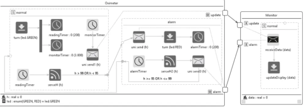
Fig. 6 Software architecture of the hospital scenario WSN
Figure 6 shows the SAML model of the WSN of the hospital scenario introduced in Section 2.3. It is important to note that this figure is actually a screenshot of the real A4WSN tool available here: http://a4wsn.di.univaq.it. From a structural point of view, the whole WSN is composed of two main components: the Oximeter com-ponent represents the software running on each oximeter node, while the Monitor component represents the software running on the monitoring station.
Oximeterstores the current percentage of oxygen in the patient’s blood as a real number in the h application data, and the current state of its status led in the led ap-plication data, which can be either RED or GREEN. At startup, this component turns the led into green via the turn(led.GREEN) actuate action and starts two cyclic timers in parallel. Every time the monitorTimer is triggered (every 3000 milliseconds), the component sends the current value of the h application data to the Monitor compo-nent via the update message port. When the readingTimer is triggered (i.e., every 200 milliseconds), the component senses the current oxygen percentage in the patient’s blood via the senseH action: if the read value is not below or above the norm (i.e., if it is not between 95% and 99%), then the component switches to the alarm mode. In this specific mode, the component firstly sends the current read value to the Monitor component via a dedicated alarm message port, then it turns the led into red, and starts a new cyclic timer with a period of 200 milliseconds. From this point onwards this component senses the percentage of oxygen in the blood of the patient and sends it to Monitor every 200 milliseconds. If the read value comes back in the acceptable range, then the component switches back to the normal mode.
The Monitor component is straightforward. It has a single operating mode in which every time a message from the Oximeter component is received, its data is shown on a display via the updateDisplay actuate action. This component temporarily stores the value received by the various oximeter nodes in data.
4.2 Node Modelling Language (NODEML)
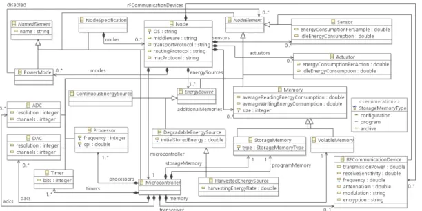
NODEML is our language for describing the low-level details of each type of node that can be used within a WSN. A NODEML model contains exclusively low-level, node-specific information. Different WSN applications can reuse the same NODEML models and organize them differently, depending on the requirements of the applica-tion. Figure 7 shows an overview of the metamodel underlying our NODEML lan-guage. In the following we provide a description of the main concepts defined in the NODEML metamodel. For the sake of brevity, we do not go into the details of each element of the language, the details are presented in the the technical report that is accessible on [38].
Fig. 7 NODEML Metamodel
A node specification is the root element of a NODEML model. It is a container of instances of the Node metaclass. A node represents a specific node type that can be used within the WSN. A node can have a name (inherited from the NamedElement metaclass), its operating system (e.g., TinyOS, Contiki, Mantis, LiteOS), middleware (such as TeenyLIME, MiLAN, RUNES [44]), transportProtocol (such as UDP and TCP), macProtocol (such as T-MAC, S-MAC, WiseMAC, SIFT [17]) and routing-Protocol(such as SPIN, LEACH, GEAR [3]) it uses to communicate with other nodes within the WSN can be specified.
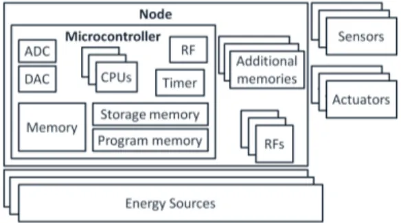
From a structural point of view, according to the NODEML metamodel a WSN node is composed of a set of node elements; in this part of NODEML, we took in-spiration from the abstract view of the low-level parts in a typical WSN node as de-scribed by Picco and Mottola in [43]. Figure 8 graphically shows how a WSN node can be represented in NODEML. According to NODEML, a WSN node contains
one or more energy sources (e.g., batteries), a microcontroller (i.e., the component mainly devoted to computation and memory management), a set of sensors, a set of actuators, a set of additional memories representing external storage memories of the node, a set of radio communication devices to communicate with other nodes within the WSN, and a set of power modes in which the node can be at any given time.
Fig. 8 an abstract view of the low-level parts of a WSN node.
An energy source represents any equipment or device used to provide electrical energy to the node. NODEML supports three types of energy sources, namely:
– ContinuosEnergySource that potentially never runs out. A classical example of this kind of energy source is AC/DC supply.
– DegradableEnergySource that can terminate at any time. As an example, batter-ies can be represented by a degradable energy source in NODEML.
– HarvestedSource that can terminate at any time and harvest additional energy in some way. As an example, in NODEML batteries coupled with a solar panel can be represented as an harvested energy source.
In NODEML, sensors are the hardware component performing the actual read-ings from the environment. Intuitively, a sensor can be seen as a unit that measures a physical quantity and converts it into a signal which can be analyzed and manipu-lated by a microcontroller. A WSN node can be equipped with zero or more sensors. Today many types of sensors exist, each of them tailored to acquire specific data from the environment; for example, a sensor can get information about the lighting conditions of the environment, its current temperature, presence of smoke or gas, the geographical position of the node, and so on [55].
An actuator is the hardware component that can physically operate on the en-vironment. Conceptually, it performs the inverse operation of a sensor, i.e., sensors acquire information from the environment and allow the microcontroller to perform some computation with it, whereas actuators are triggered by some computation of the microcontroller and then perform an action in the environment. A WSN node can be equipped with zero or more actuators. Examples of actuators include: water sprinklers, lights, electronic door locks, motors, airscrews, etc.
An RF communication device is a radio device to communicate with other WSN nodes. For example the ChipCon 24206. Technically, in NODEML an RF
communi-cation device represents an RF transceiver that can operate on specific bands, such as the 2.4 GHz ISM, XX etc., and are compliant with some IEEE standard which speci-fies their physical layer and media access control, such as the IEEE 802.15.4 [26]. Typically, those kind of transceivers are designed for low-power and low-voltage wireless applications. In NODEML, an RF communication device has some attributes related to the capabilities of the device (e.g., transmission power, frequency, etc.), their description is provided in the technical report that is accessible on [38].
A WSN node commonly requires memory as well. NODEML supports two kinds of memory:
– Volatile memory that represents the classical volatile memory in computer sys-tems. When power supply is interrupted the stored memory is lost. Usually, the size of a volatile memory in a WSN node ranges from 2Kb to 512Kb [43]. – Storage memory that represents the storage device of the WSN. This kind of
memory is usually utilised for persisting data within the WSN. Unlike the volatile memories, storage memories preserve stored data also when power supply is in-terrupted. Usually, the size of a storage memory in a WSN node ranges from 128Kb to several gigabytes [43]. According to NODEML, a storage memory can be of different types: configuration, archive, and program memory, depending on how the application uses it.
A micro-controller is an electronic device integrated into a single chip, it is com-monly used in embedded systems. Examples of micro-controllers are: ATMega128, Texas Instruments MSP430, etc. According to NODEML, a micro-controller can con-tain one or more processors, zero or more ADCs (abbreviation for Analog-to-Digital Converter) , zero or more DACs (abbreviation for Digital-to-Analog Converter), one or more timers, a volatile memory, a program memory, a storage memory, and an optional radio transceiver.
The processor is the element which physically performs the computational logic of the node. Examples of processors include 8 bit AVR Mega, ARM920T, etc. In NODEML a processor is characterized by its frequency (i.e., its clock rate) in MHz, and its cycles per instruction (CPI) representing the number of clock cycles needed for executing a single instruction.
An ADC is a device for converting a continuous physical signal into a digital value that “discretizes” it. A DAC is a device that performs the inverse operation of an ADC; it converts digital values into continuous physical signals.
Timers are devices apt to periodically trigger the clock of the WSN node. A timer can be implemented either as a hardware or software component and usually works even when the device is in sleep mode, allowing the node to switch from sleep to active power mode. In NODEML, designers can specify the number of bits of a timer (usually they are 16 or 32 bits).
Finally, a node can specify a set of power modes, each of them describing a specific configuration of the elements of the node in terms of their power state. Each
power mode identifies a set of node elements (such as memory, DAC, RF comm. device, etc.) and identifies which elements are disabled (all the other elements of the node are assumed to be active). For example, a given WSN node can have a Sensing power mode in which all the radio transceivers are disabled (thus saving all the energy needed to perform networking operations), or a WSN node can have all the sensing devices disabled, and thus focusing only on networking operations, and so on.
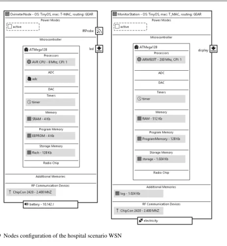
Figure 9 shows the NODEML model developed for our hospital scenario. Two node configurations have been defined:
– OximeterNode is equipped with a IRProbe sensor for sensing the percentage of oxygen in the patient’s blood and a led actuator for showing the current status of the node to the personnel of the hospital. This node is powered by two AA batteries with up to 18720 Joules and uses a Texas Instruments ChipCon 2420 RF transceiver. The micro-controller used is the low-power Atmel AVR ATmega128 equipped with an ADC for translating the analog values read by the IRProbe sensor into their corresponding digital values. The oximeter node is always active (see the active power mode).
– MonitorStation has a single actuator device for graphically showing the values re-ceived by various oximeter nodes on a digital display. Similar to OximeterNode, it uses a Texas Instruments ChipCon 2420 RF transceiver and uses low-power At-mel AVR ATmega128 micro-controller. The monitoring station is always active (see the active power mode) and is powered by a classical electrical plug con-nected to the main electrical system of the hospital. Finally, it is equipped with an additional storage memory for storing a log of all the values received by the oximeter nodes over time.
Both nodes use TinyOS7 as operating system, GEAR as routing protocol, and
T-MAC as MAC protocol.
4.3 Environment Modelling Language (ENVML)
The ENVML modelling language allows the designers to specify the physical en-vironment in which the WSN nodes are deployed. Figure 10 shows the metamodel underlying the ENVML modelling language.
The Environment represents the overall area in the 2D space in which the WSN nodes are deployed. The width and height attributes represent the dimensions in me-ters of the minimum bounding box of the environment. In geometry, a minimum bounding box is the smallest rectangle that can be drawn around a set of points such that all the points are inside it, or exactly on one of its sides. The four sides of the rectangle are always either vertical or horizontal, parallel to the x or y axis [1]. The imagePathattribute contains the path of an image file representing the modelled en-vironment in more details. It can refer to a png or jpeg image exported from a CAD software (like AutoCAD [2]), or from other design tools. The rationale behind the imagePathattribute is that environment designers may provide a more detailed view
Fig. 9 Nodes configuration of the hospital scenario WSN
Fig. 10 ENVML Metamodel
of the environment by means of external CAD software, and then our ENVML mod-els will be a projection of these modmod-els which focusses on obstacles and inner areas only.
Any kind of relevant obstacle can be placed in the environment. Each obsta-cle is characterized by the name of the material it is made of (e.g., concrete wall, wooden door, glass, etc.), and its attenuation coefficient. The latter attribute is a dec-imal number ranging from zero (when it is totally irrelevant when considering radio
signal attenuation, e.g., a sheet of paper), to one (when it totally blocks radio signals, e.g., a panel made of lead). The attenuation coefficient is one of the most important parameters when considering path loss models, network connectivity and coverage, and so on. The shape of the obstacle is given by its shell: a sequence of coordinates representing the perimeter of the obstacle in the 2D space.
In ENVML an area identifies a portion of physical environment in which nodes of the same type can be distributed according to a distribution policy (defined in the DEPML modelling language, see Section 4.5). Similar to obstacles, the perimeter of the area is defined by means of its shell.
Figure 11 shows the ENVML model representing the physical environment of our hospital scenario. It is a rectangle with 16 and 13 meters of width and height, respectively and it contains three kinds of obstacles that are concrete walls dividing the whole environment into rooms and corridors, a main wooden door on the left, and a glass door for each patients room. Each obstacle is represented by a unique name, its attenuation coefficient and the coordinates of all the points of its perimeter. The physical environment of our hospital scenario contains two main deployment areas:
– BSArea is a square area at the center of the environment and will contain the central monitoring station.
– OximetersArea its perimeter is the same as the whole physical environment and will contain all the oximeter nodes, one for each patients’ room.
Fig. 11 Physical environment of the hospital scenario WSN
It is important to note that the above mentioned solution is one of the possible ones for deployment configurations. Another solution could also be the creation of a single area for each oximiter. Each oximeter could be placed in the centre of the area. The aforementioned solutions share the same network topology.
4.4 Mapping Modelling Language (MAPML)
MAPML is our language for assigning software components to the corresponding hardware node configuration they will be executed on. Fundamentally, a MAPML model semantically represents the classical notion of deployment of software compo-nents onto hardware resources [11]. The presence of an intermediate MAPML model between an SAML and a NODEML model helps in clearly separating the application layer from all the other lower levels of a WSN. So, architects can focus on the appli-cation from a functional point of view in SAML, while other designers can focus on low-level aspects of the WSN in NODEML. This aspect is new in the Wireless Sensor Networks research area. Figure 12 shows an overview of the metamodel underlying our MAPML language.
Fig. 12 MAPML Metamodel
The root of a MAPML model is the mapping element that references the linked SAML and NODEML models via the softwareArchitecture and node containment references, respectively. The mapping element is made of a set of node mappings, each of them linking a node definition from the NODEML model and a component from the SAML model. The semantics of a node mapping is that the linked com-ponent in the SAML model will be physically deployed on the linked node in the NODEML model. A node mapping can contain a set of secondary links, each of them can be seen as a refinement of the node mapping. Secondary links are:
– SensorMapping that maps either a Sense action or a SensorInterrupt event in an SAML component to a Sensor device in a NODEML node configuration. Funda-mentally, this kind of link allows designers to specify to which physical sensor device does either a sense action or a sensor interrupt event refer to.
– ActuatorMapping that maps either an Actuate action or an ActuatorInterrupt event in an SAML component to an Actuator device in a NODEML node con-figuration. It is similar to the SensorMapping concept, but it refers to actuators, rather than sensors.
– CommunicationDeviceMapping that maps an SAML message port of the com-ponent linked by the parent NodeMapping to a NODEML radio transceiver in the node configuration linked by the parent NodeMapping. It allows designers to physically map a software port to its corresponding physical radio transceiver. – ModeMapping that maps an energy mode defined in an SAML component to
its corresponding power mode in the linked NODEML node configuration. It al-lows designers to decouple the two concepts of mode we have in SAML and NODEML, and thus it opens for a more flexible definition of modes in the pure “software world”, independently from the power modes that the WSN node has in the “physical world”.
The MAPML metamodel has some auxiliary metaclasses like MappingMod-elRef, MappingElementRef and MappingLinkEnd which are used for technical reasons . The interested reader can refer to [38] for their detailed discussion. Both the editors we developed for the MAPML language are composed of three panels that are left, centre and right. The left and right panels show the woven SAML and NODEML models, respectively, while the central panel represents various mappings of the MAPML model as a hierarchical tree. This solution allows us to provide a very clear and concise graphical editor for the MAPML model, which in some cases may have a very large number of interrelated mappings. Furthermore, we are aware that manually creating this large number of mappings can be a tedious and error-prone task for engineers; in this context, we are implementing a set of model-to-model transformations which are able to take as input an SAML model and a NODEML model, and then they are able to semi-automatically generate an initial MAPML model linking them; this operation is guided by matching strategies (e.g., name sim-ilarity via edit distance, structural simsim-ilarity, etc.). In the MDE research field this practice is called model matching [16].
For what concerns our hospital scenario, the MAPML model linking the SAML model showed in Figure 6 and the NODEML model showed in Figure 9 has the following form:
– NodeMapping oximeter links the Oximeter component to the OximeterNode node; – ModeMapping active links both the normal and alarm modes of the Oximeter
component to the active power mode of the OximeterNode node. It is impor-tant to note that operating modes defined in SAML are pure logical modes, whereas power modes defined in NODEML actually depend on the hardware configuration of the node itself.
– SensorMapping irProbe links both the SenseH(h) and SenseH2(h) SAML sense actions to the hardware IRProbe sensor in the NODEML model. – ActuatorMapping led, which is similar to SensorMapping irProbe, links both
the turn(led.GREEN) and turn(led.RED) SAML actions to the hardware led actuator in the NODEML model.
– CommunicationDeviceMapping 2420 links the update and alarm SAML mes-sage ports to the ChipCon2420 RF transceiver defined in the NODEML model. – NodeMapping monitor links the Monitor component to the MonitorStation node;
– ModeMapping active links the normal mode of the Monitor component to the activepower mode of the MonitorStation node.
– ActuatorMapping display links the updateDisplay(data) actuate SAML ac-tion to the hardware display actuator in the NODEML model.
– CommunicationDeviceMapping 2420 links the update and alarm SAML mes-sage ports of the Monitor component to the ChipCon2420 RF transceiver de-fined in the NODEML model.
With such a configuration, we now have a clear view of how various elements de-fined at the software architecture level interact with the hardware. For example, all the communication between the Oximeter and Monitor SAML components happen be-tween different WSN nodes, whereas all the other actions defined in the control flow are executed locally to the component containing them. Also, the MAPML model establishes which hardware sensor and actuator equipments are actually used for per-forming the abstract sense and actuate actions defined in the SAML model. This level of flexibility is exactly the main goal of the A4WSN modelling approach.
4.5 Deployment Modelling Language (DEPML)
DEPML is our language for virtually deploying WSN nodes into the physical en-vironment. Figure 13 shows an overview of the metamodel underlying the DEPML language.
Fig. 13 DEPML Metamodel
DEPML allows designers to consider each node configuration defined in a NODEML model and to instantiate it in a specific area within the physical environment defined in a ENVML model. A DEPML model contains a single type of link, called De-ploymentLink linking together a node configuration in NODEML and an area in ENVML. The semantics of the deployment link is that the linked node configuration is instantiated and virtually deployed in the linked area multiple times. This allow designers to focus on generic components and node types in SAML and NODEML, while in DEPML they can reason on the final deployment of the WSN. The number of nodes that are instantiated in the area is defined in the numberOfNodes attribute. Within a certain area each node configuration can be distributed in three different ways:
– random, each node is placed randomly within the area;
– grid, nodes are placed on a grid with a certain number of rows and columns; – custom, each node is manually placed within the area. In this case, each deployed
node is represented by its name (which must be unique within the area) and the coordinates of its position.
Also, nodes name patterns can be used by designers for declaring the textual pattern of the names of the nodes distributed within the area. They are used as a way to refer to the names used as targets of Send Message actions in SAML models. Similar to MAPML, also the DEPML metamodel has some auxiliary metaclasses like DeploymentModelRef, DeploymentElementRef and DeploymentLinkEnd. They are described and discussed in [38]. The DEPML modelling editor is analogous to the MAPML one. This is composed of three panels providing a tree-based representation of the NODEML, SAML and deployment links of DEPML, respectively.
For what concerns our hospital scenario, the DEPML model is very straightfor-ward. It contains a deployment link between each node defined in the NODEML (see Figure 9) and its corresponding area in the ENVML model (see Figure 11). More specifically, the DEPML model has the following elements:
– DeploymentLink oximeter links the OximeterNode NODEML node to the Oxime-tersAreaENVML area. Since we want to specify that exactly one oximeter node must be deployed in each patient’s room, we define a custom nodes ditribution. Thus, we manually define the exact position of the deployed node by means of ten DeployedNodeelements, each of them containing the coordinates of its position in the environment.
– DeploymentLink monitorStation links the MonitorStation NODEML node to the BSAreaENVML area. In this case we specify that the number of deployed node is only one, with a random distribution within the area (we can do this because the area is a square with a side of 0.5 meters, which is exactly the size of the monitoring station node).
The presented DEPML models unveil the flexibility we achieved with the A4WSN approach. Indeed, if the hospital WSN application can be reused in a different hospi-tal, the SAML, NODEML, and MAPML models can be reused as they are. The only models that must be adapted are the ENVML model for representing the new phys-ical environment with its obstacles and the DEPML model for linking the original NODEML nodes to the new areas, possibly with different values for specifying the number of deployed nodes (e.g., twenty oximeter nodes instead of ten).
In conclusion, all the proposed languages have been designed to provide a good trade-off between genericity, expressivity and accuracy in capturing the various facets of the WSN domain. To this respect, it is fundamental to allow designers to check whether their models are correct with respect to the semantics of the proposed lan-guages. More specifically, A4WSN allow designers to check whether a model adheres to the structural semantics of its corresponding language (e.g., SAML). A4WSN sup-ports this feature by leveraging the well-known notion of conformance in Model-Driven Engineering; in other words, in A4WSN a model m adheres to the structural semantics of its corresponding language (e.g., SAML) if and only if m actually
con-forms to its metamodel (e.g., the SAML metamodel introduced in Section 4.1). Fur-thermore, in order to ensure a more precise semantics of the languages described in Section 4, we complemented them with fourteen OCL8 constraints. For example, in NODEML a constraint ensures that each instance of Node must contain at least one program memory, another constraint in DEPML ensures that the coordinates of each manually positioned node must be within the boundaries of the area it is deployed in, and so on. For the sake of readability the description of such constraints are not discussed extensively. If the need for more strict semantics of the proposed languages arises (for instance in order to define WSN applications with specific styles or spe-cial configurations), additional OCL constraints can be added to every element of the languages by extending the A4WSN platform with a suitable plugin. Please, refer to Section 5 for more details on this feature of the A4WSN platform.
5 The Programming Framework
As introduced in the beginning of Section 3, the A4WSN platform is composed of two main parts that are a modelling environment to allow architects to model WSN applications and a programming framework devoted to code generation and analy-sis of WSN application models. The motivation for performing code generation and analysis of WSN application models are well understood both in academia and in practice [51, 36]. Basically, code generation helps in reducing the cost of developing a WSN application since the developers can automatically obtain an executable ap-plication from the model by applying some specific transformations. Also, perform-ing analysis is fundamental while developperform-ing a WSN application due to the intrinsic complexity of the WSN domain. For example, if we consider typical aspects in WSN development such as nodes connectivity, real-time communication, energy consump-tion, performance, security, etc., it is extremely difficult and demands for a lot of effort to ensure that a developed WSN is correct with respect to those aspects. More-over, analysis engines can also be used to reason on the WSN configuration in order to find reasonable trade-offs in terms of network topology, employed protocols, etc. for a specific task.
In this section we present the generic and extensible programming framework of A4WSN. It is tailored to support the development of code generation and analy-sis engines against WSN application models conforming to the modelling languages described in Section 4.
Our programming framework provides a generic workbench and a set of exten-sion points for supporting the development and integration of third-party code gener-ation and analysis engines. More specifically, through its components, it enables the storage of WSN models, supports the merging of linked models, validates A4WSN models, provides error/warning/information messages to the user, defines a UI man-ager to make plugins interacting, provides facilities for managing code generation and analysis engines.
Third-party engines are realised as plugins extending the A4WSN generic work-bench. It knows at run-time which plugins are available and automatically provides to the user the available target implementation languages and analysis techniques.
Fig. 14 The A4WSN programming framework
Figure 14 shows an overview of the A4WSN programming framework. All the boxes within the programming framework represent the various components of the generic programming workbench, whereas the C1..Cn and A1..An boxes represent
third-party code generation and analysis plugins, respectively. Third-party plugins extend the Code Generation Manager and Analysis Manager components which pro-vide the needed extension points and they communicate with all the other components of the programming framework (for the sake of clarity we do not show those connec-tors in the figure). In the following we will discuss the facilities and duties of the various components of the generic A4WSN programming framework, an overview of their implementation details is provided in Section 6.
5.1 Models
The central element of the programming framework is the Models repository that stores all the WSN models developed by architects and designers. Indeed, stored models can conform to any modelling language described in Section 4 which are SAML, NODEML, ENVML, MAPML, and DEPML. The models repository can be realised in different ways. For instance it may directly rely on the file system of the machine running the A4WSN platform (this is the solution implemented in the current version of the A4WSN tool), it may point to resources stored in the cloud or it may refer to some in-memory models representation. If on one side this feature of the models repository is very flexible in terms of resources consumption and localisation, on the other side it opens for possible problems of interoperability between all the
other components of the A4WSN programming framework. This is exactly why the Model Adapter component exists.
5.2 Model Adapter
The model adapter is a component which abstracts the nature of the models repository to the other components of the A4WSN programming framework. The model adapter is composed of a set of connectors (each of them tailored to a specific models storage type) that expose a common interface to all the other components to access various elements of the models in a homogeneous way. Also, the Model Adapter component has a built-in model transformation, called Merger, that can merge linked models defined in the A4WSN modelling environment. If we consider Merger as a function, it can be defined as follows:
M erger: M MSAM Lx M MN ODEM Lx M MEN V M Lx M MM AP M Lx
M MDEP M L→ M Mmerge
where each M Mxis the metamodel of the x modelling language, where x can vary
between SAM L, N ODEM L, EN V M L, M AP M L, DEP M L, and M Mmerge
is the union of all the M Mxmetamodels. In other words, Merger takes as an input
an instance of each modelling language defined in the A4WSN modelling environ-ment and provides a single model conforming to a unique metamodel as an output. The reason behind the existence of the Merger transformation is that currently many approaches and tools for code generation and analysis assume to have a single model as an input, rather than a set of models conforming to different languages. In order to alleviate this issue with current approaches and tools (which could have hampered the usefulness of the whole A4WSN platform), we decided to implement the Merger as an internal transformation to merge separate models into a single one. Merger can be executed at any time by plugin developers by calling a dedicated Java method.
5.3 Validation
The Validation component executes all the operations to validate A4WSN models: – it checks whether one of the A4WSN models conforms to its corresponding
meta-model (metameta-models are described in Section 4);
– it executes all the OCL constraints defined in each metamodel within the A4WSN platform and checks whether they are satisfied or not;
– if defined, it executes the additional OCL constraints that are defined in some code generation or analysis plugin and checks whether they are satisfied or not. The result of a validation operation is composed of four main elements: (i) a boolean value representing whether the involved model passes all the checks listed above, (ii) a set of informative messages that describe the result of the validation in a human-readable way, (iii) a set of in-memory representations of all the elements in the models which do not satisfy some of the checks listed above, and (iv) a set of actions that can be executed by the A4WSN platform as a quick fix of the identified
violations (quick fix operations can be defined in the plugins extending the A4WSN platform).
The Validation component communicates with Model Adapter in order to access various elements of the models to be validated. Also, it communicates with the Mes-sages Manager and the UI Manager components to show the informative mesMes-sages belonging to M to the user and to highlight the elements in their graphical editor violating the constraints, respectively.
5.4 Messages Manager
The Messages Manager component serves to graphically show informative messages to the user. A4WSN supports three kind of informative messages which are error, warning and information. Plugin developers can decide the type of each message to be shown, depending on its severity. Each message is defined as a couple < K, T >, where K represents the type of message (i.e., error, warning, or information) and T represents the textual content of the message in a human readable way.
5.5 UI Manager
The UI Manager component is responsible for the main facilities interacting with the user interface of the A4WSN platform9. The UI Manager component provides all the graphical facilities to interact with the plugins and elements of the A4WSN platform, which are:
– Code Generation Engines View: a dedicated view showing a list of all the avail-able code generation engines (with their description, icon, name, etc.), together with their management facilities, such as code generation activation, code gener-ation results viewer, etc.;
– Analysis Engines View: a dedicated view showing a list of all the available analy-sis engines (with their description, icon, name, etc.), together with their manage-ment facilities, such as analysis activation, analysis results viewer (significantly different from the code generation results viewer), etc.;
– Code Generation Contextual Menu: a contextual menu that triggers the execution of a code generation engine. A contextual menu is associated to each model of the A4WSN modelling environment;
– Analysis Contextual Menu: a contextual menu that triggers the execution of an analysis engine. A contextual menu is associated to each model of the A4WSN modelling environment;
– Validation Trigger: a contextual menu and a dedicated button in the graphical ed-itor of each model of the A4WSN modelling environment that triggers the valida-tion of the current model. Opvalida-tionally, the user can identify which plugin contains additional constraints to be checked. The results of the triggered validation are managed by the Messages Manager component;
9 Also the Messages Manager interacts with the UI of the A4WSN platform, however its impact to the UI is much more limited than that of UI Manager.
– Code Generation and Analysis Progress Feedback: provides an element in the UI that graphically shows the progress of the triggered code generation or analysis. A4WSN provides two types of progress feedback, a progress bar for activities in which all the steps are known a priori and a round indicator for activities with an unknown length.
– Plugin Additional Parameters View: provides a dedicated view in which users can provide additional parameter to be passed to the code generation or analysis engine being triggered. Plugin developers can specify the number, name, and type of those parameters by using a specific extension point.
5.6 Parameter Provider
Parameter Provider component manages the additional parameters that a code gen-eration or analysis plugin may require for carrying on its activities. As previously mentioned, additional parameters are defined by using a specific extension point of the A4WSN programming framework; each parameter is defined as a triplet < name, T, def ault >, where name is the unique name of the parameter, T is the type of the parameter, and def ault is the optional default value of the parameter. Available parameter types are listed below.
– String: a textual value;
– Integer: an integer numerical value; – Float: a decimal numerical value; – Boolean: a boolean value;
– Local Resource: a file in the local file system of the user, it is referenced by its path in the file system;
– Remote Resource: a resource in the cloud that can be accessed by a standard HTTP GET request and is referenced by its URL.
Once the user has provided the values of the additional parameter of a code gen-eration or analysis engine, the Parameter Provider component makes them available to the plugin realizing the engine so that it can access them before actually executing the activity which is being triggered by the user.
5.7 Code Generation Manager
The Code Generation Manager provides a set of facilities for managing code genera-tion engines and the extension point that is used by code generagenera-tion plugin developers (see Section 5.9 for more details). For instance it checks which plugins are currently extending its extension point and makes their facilities available to the end user. It includes all the registered code generation plugins into the Code Generation Engines Viewof the UI Manager. It loads plugins into the contextual menus of the A4WSN modelling environment. It automatically triggers the validation operations defined by the plugins before executing the actual code generation operation. Also, the Code Generation Manager component exposes a common Java API to plugin developers,