Steel-based applications
in earthquake-prone areas
(STEEL-EARTH)
Research and InnovationEUR 28459
EN
ISSN 1831-9424 (PDF) ISSN 1018-5593 (Printed)EUR
28459
Steel-based applications in earthquak
e-prone areas (STEEL
-EARTH)
EUROPEAN COMMISSION
Directorate-General for Research and Innovation
Directorate D — Industrial Technologies
Unit D.4 — Coal and Steel
E-mail: [email protected]
[email protected]
Contact: RFCS Publications
European Commission
B-1049 Brussels
European Commission
Research Fund for Coal and Steel
Steel-based applications in earthquake-prone areas
(STEEL-EARTH)
S. Caprili, W. Salvatore
University of Pisa - Largo L. Lazzarino 1, 56122 Pisa, Italy
B. Hoffmeister, H. Bigelow
RWTH Aachen University - Templergraben 55, 52056 Aachen, Germany
Spyros A. Karamanos, T. Papatheocharis
University of Thessaly - Argonauton & Filellinon, 38221 Volos, Greece
M. Hjiaj, H. Somja
INSA de Rennes - CS 14315, Avenue des Buttes de Coesmes 20, 35043 Rennes, France
A. Zona, A. Dall’Asta, G. Leoni, D. Quattrini, F. Scozzese
University of Camerino - Piazza Cavour 19F 62032 Camerino, Italy
L. Fülöp
VTT Technical Research Centre of Finland - Tekniikantie 4A, 02044, Espoo, Finland
L. Bianco, R. Mallardo, P. Filipuzzi
Ferriere Nord S.p.A - Zona Industriale Fraz. Rivoli, 33010 Osoppo-Udine, Italy
H. Degée
Hasselt University, Faculty of Engineering Technology - Agoralaan, Gebouw H, B-3590, Diepenbeek, Belgium
Université de Liège, Département Argenco - Quartier Polytech, 1, Bâtiment B52, B-4000 Liege, Belgium
F. Braga, R. Gigliotti, R. Laguardia, M. D’Agostino, M. Ventrellla
University of Roma La Sapienza - Piazzale Aldo Moro 5, 00185 Roma, Italy
P. Tsintzos
SHELTER S.A., 6th km Larissa – Sykouriou 41500 Larisa, Greece
N. Signorini, G.F. Bortone
Coordinamento Sismico Regione Toscana - Piazza Del Duomo 10, 50122 Firenze, Italy
V. Dehan, C. Haremza
ECCS – Avenue des Ombrages 32/20, 1200 Bruxelles, Belgique
D. Dubina, A. Stratan, A.Dogariu
Politehnica University of Timisoara - Piata Victorei, 2, 300006 Timisoara, Romania
T. Sullivan
EUCENTRE - Via Ferrata 1, 27100 Pavia, Italy
G. Royer-Carfagni, L. Galuppi, A. Franco
University of Parma - Via Università 12 43100 Parma, Italy
S. Baragiola
Riva Acciaio S.p.A. - Viale Certosa 249 20151 Milano, Italy
Grant Agreement RFS2-CT-2014-00022
1 July 2014 to 31 December 2015
Final report
Directorate-General for Research and Innovation
LEGAL NOTICE
Neither the European Commission nor any person acting on behalf of the Commission is
responsible for the use which might be made of the following information.
The views expressed in this publication are the sole responsibility of the authors and do not
necessarily reflect the views of the European Commission.
More information on the European Union is available on the Internet (http://europa.eu).
Cataloguing data can be found at the end of this publication.
Luxembourg: Publications Office of the European Union, 2017
ISBN 978-92-79-65676-7
ISSN 1018-5593
doi:10.2777/38007
KI-NA-28-459-EN-C
ISBN 978-92-79-65675-0
ISSN 1831-9424
doi:10.2777/57634
KI-NA-28-459-EN-N
© European Union, 2017
Reproduction is authorised provided the source is acknowledged.
Europe Direct is a service to help you find answers
to your questions about the European Union
Freephone number (*):
00 800 6 7 8 9 10 11
3
Table of Contents
Table of Contents ... 3
Final Summary ... 5
Objectives of the project ... 7
Description of the activities developed inside STEEL-EARTH project ... 8
1.
WP1: arrangement of technical sheets and working examples ... 8
1.1
Design of steel and steel-concrete buildings ... 8
1.1.1
Steel industrial building with HR profiles ... 8
1.1.2
Steel industrial building with LGS profiles ... 10
1.1.3
Steel industrial building with WT sections ... 12
1.1.4
Steel-concrete commercial buildings with different bracing systems ... 13
Comparison of proposed bracing systems for composite commercial buildings ... 17
1.1.5
Steel-concrete commercial building with enhanced passive dissipative system ... 18
1.2
Retrofit of existing buildings ... 21
1.2.1
General indications for the retrofit of existing buildings ... 22
1.2.2
Indications for the seismic rehabilitation of the foundation system ... 24
1.2.3
Indications for the seismic rehabilitation of vertical systems ... 25
Indications for masonry buildings ... 27
Indications for r.c. frames with introduction of bracing systems ... 28
2.
WP2: arrangements of pre‐normative background documents ... 37
2.1
Pre-normative document for standards’ harmonization ... 37
2.1.1
General presentation of the problems ... 37
2.1.2
Results of further investigations basing on Opus results ... 40
Objective A ... 40
Objective B ... 41
Objective C ... 41
2.2
Background documents with indications for the retrofit of existing constructions ... 42
2.2.1
Performance Based Seismic Design - PBSD ... 42
2.2.2
Rules for rehabilitation of existing constructions ... 44
Guidelines for the design of retrofit with SSW ... 44
Guidelines for the design of retrofit with BRB... 47
Guidelines for the retrofit of existing precast buildings ... 49
2.2.3
Rules for the design of systems with SSCD ... 52
3.
WP3: translation of documents and website for dissemination ... 56
3.1
Translation of documents ... 56
3.2
Organization of the STEEL-EARTH website ... 56
3.3
Dissemination through Facebook and LinkedIn profiles ... 59
4.
WP5: Organization of workshops and dissemination activities ... 60
4.1
International workshops ... 60
4.1.1
Workshop in L’Aquila, Italy ... 61
4.1.2
Workshop in Tampere, Finland ... 62
4.1.3
Workshop in Ljubljana, Slovenia ... 65
4.1.4
Workshop in Madrid, Spain ... 65
4.1.5
Workshop in Aachen, Germany ... 65
4.1.6
Workshop in Cluj-Napoca, Romania ... 69
4
4.1.8
Workshop in Coimbra, Portugal ... 69
4.1.9
Workshop in Volos, Greece ... 70
4.1.10
Workshop in Hasselt, Belgium ... 70
4.1.11
Final STEEL-EARTH workshop ... 76
4.2
Conferences in Emilia-Romagna ... 81
4.3
Training courses at EUCENTRE, Pavia (Italy) ... 85
5.
Conclusions ... 86
6.
Exploitation and impact of the research results ... 87
List of Figures ... 88
List of Tables ... 91
List of Acronyms and Abbreviations ... 92
5
Final Summary
STEEL-EARTH (Steel-based applications in earthquake prone areas, RFS2-CT-2014-00022) dissemination project is based on the results obtained inside three finished and approved RFCS projects:
PrecaSteel (RFSR-CT-2007-00038, 2007-2010): Prefabricated steel structures for low-rise
buildings in seismic areas.
SteelRetro (RFSR-CT-2007-00050, 2007-2010): Steel solutions for seismic retrofit and
upgrade of existing constructions.
Opus (RFSR-CT-2007-00039, 2007-2010): Optimizing the seismic performance of steel and
steel-concrete structures by Standardizing material quality control.
In the framework of PrecaSteel project, a deep investigation about the industrial and commercial buildings diffused in Europe, including technical and economic aspects, was executed. The project aimed to define pre-designed steel solutions for the realization of single-storey industrial and low-rise commercial buildings in earthquake-prone areas. Specific practical tools were developed for the preliminary design and cost estimation of considered buildings; the cost model adopted for the analyses was based on specific investigations executed at European level including construction, transportation and assembly economic efforts.
SteelRetro research project aimed to design innovative steel-based solutions for the rehabilitation
of existing r.c. and masonry buildings, reducing seismic vulnerabilities and satisfying the actual safety requirements. The selection of the optimal retrofit technique shall account for feasibility and economic aspects, limiting the post-earthquake intervention costs and providing, if possible, the increase of the degree of standardization. The Performance Based Seismic Design (PBSD) approach was suitably modified for the application to existing buildings.
Opus research project aimed to analyze the influence of the variability of materials’ mechanical
properties on the ductile behaviour of steel and steel/concrete composite structures. Basing on the results of statistical investigations and numerical analyses, recommendations for the design of different structural typologies were developed. The effectiveness of introducing an upper limitation
on yielding strength Re as additional check for the seismic qualification of EN10025, the influence of
the overstrength material factor γov (EN 1998-1:2005) and the efficiency of the capacity design
procedure for the design of new buildings were investigated.
The dissemination project Steel-Earth aims to spread the results obtained inside SteelRetro,
PrecaSteel and Opus among engineers, technicians, construction companies, standardization bodies
and institutes through the elaboration of technical sheets (TS), practical applications (WE), background documents and design guidelines to be proposed to national and international committees as well as to the commissions for the improvement of actual Eurocodes.
One of the main topics of the project concerns the design of steel and steel/concrete commercial and industrial buildings: simple procedures, able to optimize the structural dissipative behaviour of buildings designed for earthquake prone areas as well as the economic effort for their realization, have been elaborated. The procedures developed inside PrecaSteel for the design of commercial and industrial buildings have been applied to selected representative case study buildings, allowing the elaboration of a codified methodology usable by technicians and engineers. Technical sheets (TS) and corresponding working examples (WE) concerning the seismic design of buildings with different structural typology, functional destination, elements’ section (Hot-Rolled profiles – HR, Light Gauges Steel profiles – LGS and Welded Tapered profiles – WT) and bracing systems (traditional braces, r.c. precast shear walls, passive protection devices) have been developed and detailed with executive drawings in Work Package 1.
Practical indications regarding the application of steel-based rehabilitation techniques to existing buildings, including both r.c. and masonry constructions, have been developed in Work Package 1. Basing on the solutions developed inside SteelRetro and following the modified PBSD procedure, technical sheets (TS) and practical examples (WE) have been elaborated analysing the application of several different techniques (traditional bracing systems, dissipative self-centering devices, steel shear walls, Buckling Restrained Braces, etc.), evaluating the feasibility and the economic impact of proposed rehabilitation operations.
All the TS have been collected in the deliverable D.1.1, while the WE are grouped in deliverable D.1.2 (in English language). The results obtained in WP1 concerning the design and the rehabilitation of buildings have been used to elaborate background documents and general guidelines, mainly devoted to industrial and commercial constructions, according to what foreseen in Work Package 2 (WP2).
The results coming from Opus, about the influence of material mechanical properties on the ductile behaviour of different structural typologies and the problems due to the differences among design and production standards, have been elaborated in WP2 and collected in a useful pre-normative document (deliverable D.1.2). In particular, three main design aspects have been further investigated inside Steel-Earth. The first one concerns the possibility to adopt “real” values of the
6
material overstrength factor γov (i.e. values coming from the statistical investigations executed in
Opus) in the design of structural elements following Eurocode 8; the influence of γov in the design
of details and connections, especially for what concerns beam to column connections and foundation joints, has been also taken into consideration (second topic). The third aspect investigated is related to the effect of the variability of mechanical properties on the global behaviour of buildings designed considering nominal properties, analysing the efficiency of the capacity design approach in the protection of non-dissipative members.
The results of the above mentioned elaborations (including TS, WE, background and pre-normative documents) have been translated several languages, including French, German, Italian, Greek and Romanian (these last two ones only for TS and WE), according to what foreseen in Work Package 3 (WP3).
In order to better disseminate the activities developed inside Steel-Earth and to distribute the knowledge and obtained results among engineers, technicians, academic people etc., a website of
the project (https://www.steelconstruct.com/site/) has been organized and translated into several
languages, according to what foreseen in Work Package 3 (WP3). A Facebook and a LinkedIn profiles have been created to be adopted as mean of communication able to attract young engineers, students, etc.
According to WP5, 11 workshops, 5 conferences and 2 training courses have been organized. Workshops have been held in Tampere (Finland), Volos (Greece), Timisoara (Romania), Ljubljana (Slovenia), Hasselt (Belgium), Aachen (Germany), L’Aquila (Italy), Coimbra (Portugal), Cluj-Napoca (Romania) and Madrid (Spain); the 5 conferences have been held in Emilia – Romagna (in Parma, Bologna, Ferrara, Modena and Mantova, Italy) and the two training courses for engineers at EUCENTRE (Pavia, Italy). The events have been published through the website, Facebook, LinkedIn and through the distribution of brochures opportunely prepared in different languages.
During the events, booklets, CDs/DVDs and pen drives containing the technical sheets, working examples, background documents and presentations executed have been provided to the attending people.
7
Objectives of the project
The Steel-Earth dissemination project aims at distributing among technicians, engineers, design companies and standardization bodies the results achieved into three past research projects dealing with the design of new steel and composite buildings and the retrofit of existing r.c. and masonry constructions using new developed methodologies and enhanced steel-based systems. In Work Package 1 technical documents related to both design and rehabilitation have been prepared on the base of previous results of PrecaSteel [1] (i.e. design) and SteelRetro [3] (i.e. retrofit) projects; for each of the presented design approaches as well as for each of the steel-based retrofit systems specific practical applications (i.e. Working Example – WE) have been developed. All the documents of WP1, summarized in deliverables D.1.1 and D.1.2, have been collected in the final proceedings of Steel-Earth final workshop and distributed to the attending people, providing full dissemination of the obtained results.
In Work Package 2, on the base of the design and retrofit indications adopted for new and existing buildings coming from the practical applications of WP1, background documents have been prepared (deliverables D.2.2 and D.2.3). The analysis of the efficiency of the actual overstrength
coefficient factors (ov and Ω) in the design of ductile buildings in seismic areas, based on the
results obtained in Opus [2] with further investigations executed inside Steel-Earth, has been translated into a pre-normative document (deliverable D.2.1), also concerning problems due to the actual differences among design and production standards.
In Work Package 3 translations of technical sheets (TS), working examples, background and pre-normative documents coming from WP1 and WP2 into several languages (including French, German, Italian, Greek and Romanian) have been executed (deliverables D.3.1 and D.3.4). Translations allow the spread of obtained results and indications among European technicians, engineers and design companies. All the documents are available at the website opportunely
organized inside the project (https://www.steelconstruct.com/site/), providing information
regarding the partnership, dissemination activities, objectives and results.
The dynamic web-pages elaborated in the framework of PrecaSteel [1] research project have been
made available at the link http://riv-precasteel.rivagroup.com/ constituting a relevant tool for the
design of steel and composite solutions for industrial and commercial buildings (Work Package 4).
Dissemination activities were organized inside Work Package 5, including workshops all around Europe, conferences and training courses for engineers, designers, technicians and academic people. During dissemination activities, the technical documents, the practical applications and the guidelines concerning both design and rehabilitation of buildings were provided to the attending people though the distribution of USB flash drives, brochures and printed proceedings. Such documents were also distributed during the final workshop of the dissemination project, held in Napoli in April 2016, in occasion of the meeting of CEN/TC 250/SC 8/WG 2 "Steel and Composite
8
Description of the activities developed inside STEEL-EARTH project
1.
WP1: arrangement of technical sheets and working examples
1.1 Design of steel and steel-concrete buildings
In WP1 technical documents (TS) regarding design approaches for industrial and commercial buildings in seismic area were elaborated; the corresponding practical applications (WE) provided a codified methodology to be followed for the different proposed structural solutions.
Prefabricated steel and steel/concrete composite buildings for industrial and commercial activities, characterized by different plan and elevation configurations, different number of storeys, different adopted elements’ typology and different seismicity levels were considered and deeply analyzed. The feasibility of the different proposed solutions was also considered, analysing the possibility to realize connections, executive details and, if possible, evaluating the production costs.
The work was based on the results of PrecaSteel project [1]: the structural solutions defined during
the research, further improved by the practical applications developed inside Steel-Earth, were conceived in order to represent an effective alternative to r.c. solutions, coupling structural efficiency and costs’ control of theconstruction.
The produced documentation, globally collected into deliverables D.1.1 (for TS) and D.1.2 (for WE) and, moreover, in the proceedings of the final workshop of the project, constitutes a useful tool for engineers involved in the design of selected structural typologies, providing indications for design optimization and executive details for applications.
The TS and corresponding WE show the design procedures defined and applied to three different solutions for steel industrial buildings, mainly varying from one another for the adopted sections’ profiles, and to three composite solutions for commercial buildings, differing for the typology of adopted bracing system.
The list of considered structures is presented below:
Steel industrial building with hot-rolled profiles (HR).
Steel industrial building with light gauge profiles (LGS).
Steel industrial building with welded-tapered sections (WT).
Steel-concrete commercial building with steel braces.
Steel-concrete commercial building with prefabricated r.c. walls.
Steel-concrete commercial building with enhanced passive dissipative system.
1.1.1 Steel industrial building with HR profiles
HR profiles (IPE, IPN, HE and L) are usually adopted as primary elements for steel industrial buildings designed in seismic areas; several structural configurations with different number of bays and span length, different height, different materials, bolts, typology of non-structural elements, etc. can be used, resulting in a large variety of possible combinations.
Basing on the results of PrecaSteel project [1] and reducing the number of combinations between the various parameters due to practical considerations, a design methodology for the design of industrial buildings with HR sections is proposed in Steel-Earth, also including economic aspects. The design process can be summarized in the following steps:
[1]
Definition of the structural geometry: single or double span frames with different length(16.032.0 m), repeated in the out-of-plane direction with constant distance, columns’ height between 6.0 m and 8.0 m, roofing slope equal to 15%, etc. can be considered.
[2]
Definition of the structural typology: a combined MRF (in-plane direction) and CBF(out-of-plane direction) has been selected as convenient configuration. The bracing system is generally placed at the middle of the structure.
[3]
Selection of elements sections: HR sections for the main structural elements (HEA forcolumns and IPE for beams) and truss girders instead of simple beams in case of large span have been used. CHS profiles for the bracing system of the structure, IPE and UPN for all the purlins supporting the roof and side cladding, truss girder and/or simple beams in relation to length for the horizontal elements of the MRF can be adopted.
[4]
Material choice: S275 (preferred); higher steel grades can be adopted.[5]
Modelling and analysis: linear elastic analysis of the building (static and/or dynamic)following Eurocode rules (EN1993-1-1:2005 [4], EN1998-1:2005 [4]) and considering ULS and SLS requirements can be used. A behaviour factor q equal to 1.50 is suggested. Additional checks through more refined nonlinear analyses can be executed.
9
[6]
Selection of non-structural elements: the typology of claddings and infill panels shall beselected in relation to use requirements.
[7]
Design of structural elements and connections: structural members (beams, columns,braces and purlins) and connections shall be designed according to actual standards (EN1993-1-1:2005 [4], EN1998-1:2005 [4]). Analysis of the performance of the purlin bracing system (as recommended by prEN1993-1-1) to prevent the main beams against lateral-torsional buckling shall be executed.
[8]
Costs’ Estimation: construction cost estimation, based on the total weight of steel derivedby the design solution, has been executed. The cost of workmanship, as well as the cost of transportation, have been also estimated.
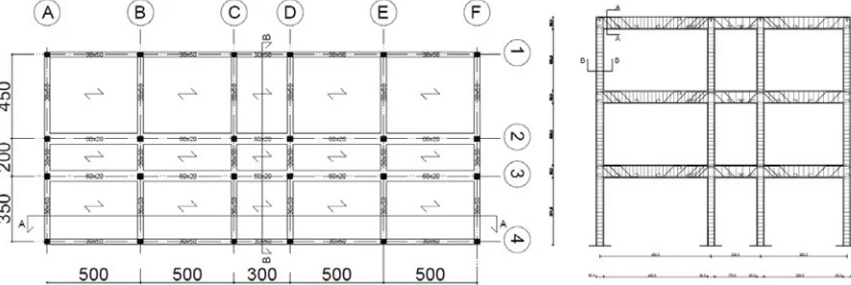
The above described design methodology has been directly applied to the industrial one bay steel building case study represented in Figure 1. The design actions coming from linear analyses are presented, as an example, in Figure 2.
Figure 1: Single bay steel industrial building (3-D view) designed adopting HR sections.
Figure 2: Bending and shear forces on the typical MRF frame coming from analysis.
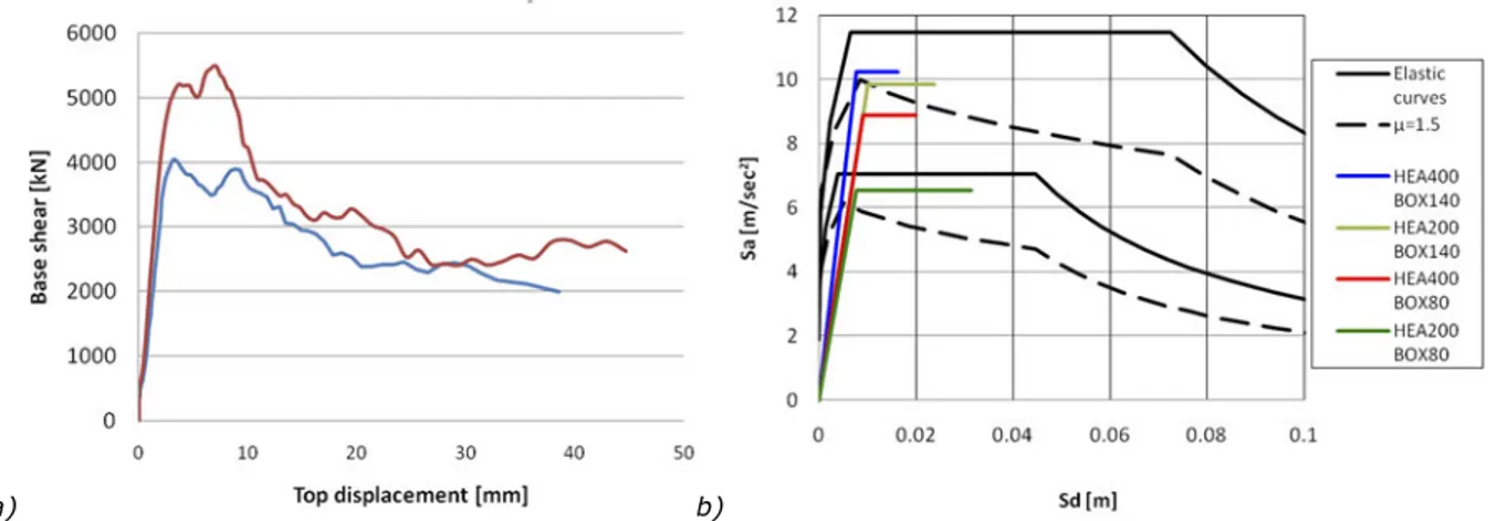
The TS and the corresponding WE evidenced, beside the efficacy of the traditional approach for the design of an industrial building in high seismicity region, the need of providing the purlins with bracing systems to improve the performance of the main beams against lateral-torsional buckling. In the case of the typical beam presented in Figure 3, two different layouts have been considered and analyzed concerning the type of connection between purlin and main beam (i.e. purlin continuous over the main beam and purlin consisting of two parts pinned on the main beam). Two different support conditions have been moreover examined and compared for the main beam: in the first case, the main beam has been assumed “simply supported” (condition typical of buildings with vertical braces resisting the horizontal actions and beams bearing only the vertical loads); in the second case, the beam acts as part of the main frame (i.e. the left end is fixed, the right one is free in the vertical direction, all the rotations are restrained).
The execution of more refined nonlinear static analyses (Figure 4), as presented in the WE, allowed to evaluate the influence of the purlin-to-beam connection on the buckling behaviour of the beam as well as the influence of the role of imperfections in the modelling procedure and in the following expected results. More details and the whole application of the procedure presented can be found in the TS and corresponding WE in deliverables D.1.1 and D.1.2.
10
a) b)
Figure 3: The geometry of the problem examined.
a)
b)
Figure 4: a) Force - vertical displacement curve for different configurations; b) Force - vertical displacement curve comparing the behaviour of main beam with different purlin-to-beam connections,
1.1.2 Steel industrial building with LGS profiles
Light-Gauge Steel (LGS) profiles are commonly used as secondary structural elements for buildings, including industrial applications (e.g. purlins, side-rails, sheeting); more recently, LGS profiles have been introduced for the design of primary structural elements (Figure 5) partially replacing HR sections, also in the case of high span length (using LGS truss systems).
Since pinned connections are generally adopted, the most conditioning design aspect is the fulfilment of SLS limitations, even in the case of portals with truss-beams with higher stiffness. The role of the roof and of wall sheeting is, therefore, fundamental to contribute to the global stiffness of the building.
The main advantage of the adoption of such systems consists in the easy manufacturing of LGS elements, despite the higher costs of the production process respect to traditional solutions.
11
a) b)
Figure 5: Overall view of industrial buildings made of LGS profiles by a) frame system and b) truss. In the TS and in the corresponding WE an example of design of an industrial steel building with LGS profiles is presented, including both technical and economic aspects. The design process can be summarized in the following steps:
[1]
Determination of the main geometry of the building: plan and elevation geometry,number of span, span length, height of the building.
[2]
Determination of design action and load combination: evaluated according to Eurocode 1[6] and Eurocode 8 [5].
[3]
Selection of elements section: LGS profiles are selected for primary elements. Sinceeffective LGS section calculation is not normally included in software and the adoption of the cross-section geometry leads to a global over-estimation of members’ stiffness, LGS sections can be “manually” introduced for pre-calculated section properties.
[4]
Selection and design of secondary elements - claddings: roof cladding shall be designedconsidering fundamental load combination, wall claddings have to face wind loads acting perpendicularly to their plane. Tables are used to estimate the ULS and SLS loads for the adopted cladding configuration; pull-out of connections shall be checked.
[5]
Selection and design of purlins and side rails: profiles with galvanized cold-formed Z, C, and Ω sections of Class 4 have been adopted according to EN 1993-1-3 [12], designed using tables provided by manufacturers.
[6]
Design of the bracing system: since the introduction of braces considerably increases thecomplexity of the design, especially for what concerns connections, if possible, the use of diaphragm effect of the roof is strongly advisable.
[7]
Modelling and analysis: preliminary linear analyses shall be executed on 3D FE models ofthe building, adopting a suggested behaviour factor equal to 1,50. The stiffness contribution of claddings shall be directly introduced in the modelling. Local buckling, distortion due to the stress concentration at the frames connections and imperfections are possible to predict, while plate buckling of the LGS members cannot be included in the model. Nonlinear analyses can be also carried out to confirm or, otherwise, to modify the preliminary design.
[8]
Design of connections and details: foundation joints and gable frames are pinned:in-plane stability is provided by diaphragm effect of the wall sheeting. The global response of the building is ensured by exploiting roof and wall diaphragm effect.
Figure 6: Example of details and connections.
The proposed methodology and its application to a case study building can be found in TS and WE and in the corresponding deliverables D.1.1 and D.1.2.
12
1.1.3 Steel industrial building with WT sectionsWelded-Tapered (WT) profiles for single and multi-span industrial buildings are currently used with the aim to optimize sections towards acting loads. WT members may be tailored for a specific application or pre-designed in producer catalogues (Figure 7).
Since sections are optimized, WT frames result in less material consumption if compared to similar frames with HR profiles; however, manufacturing is more challenging, especially due to the tendency of distortion of the long welded members. Moreover, due to the higher slenderness of WT frame members compared to HR ones, transport and lifting may also present additional problems: these aspects make the feasibility of WT frames a “balance” between material costs and labour.
a)
b) c)
Figure 7: a) Welded-tapered frame configuration with height variation of both column and beam section bending moment diagram from vertical (b) and horizontal (c) loads.
Secondary elements of the structure are usually based on cold-formed purlins and side railing; claddings are mostly corrugated sheets, sandwich panels or cassettes. The introduction of bracing system is generally required only in the longitudinal direction, since frames themselves have enough strength and stiffness.
Supports of WT frames are usually pinned to minimize foundation sizes; fixed supports can be considered if the design is governed by limiting lateral deflection or buckling lengths of columns. Depending on the climatic conditions, especially snow load, the primary objective of the design is to resist vertical action; in the case of high span length or very high frames the deflection and sway criteria may become dominant in the design. Seismic action shall be considered if needed and a low dissipative design concept (low q factor) can be used without increasing costs. The use of diaphragm action of the roof sheeting to homogenize the seismic response can eliminate the need of roof bracing.
In the TS and in the corresponding WE an example of design of an industrial steel building with WT profiles is presented, including both technical and economic aspects. In particular, the following aspects have been accurately taken into account.
[1]
Determination of the main geometry of the building: plan and elevation geometry, numberof span, span length, height of the building. Typical configurations has span length between 12 and 30 m and height between 6.0 and 8.0 m
[2]
Determination of design action and load combination: evaluated according to Eurocode 1[8] and Eurocode 8 [5].
[3]
Material choice: the usual grades adopted are S235, S275, S355 and S450.[4]
Selection of elements section: primary elements with variable cross-section for structuraldesign optimization.
[5]
Selection and design of secondary elements – claddings: design of roof claddings executedconsidering fundamental load combination, wall claddings designed to face wind loads acting perpendicularly to the plane of the cladding. Tables are generally used to estimate the ULS and SLS loads for the adopted cladding configuration; pull-out of cladding connectors shall be checked.
[6]
Selection and design of secondary elements – purlins and side rails: cold formed profiles13
[12]. The design of such elements is traditionally executed using design tables provided by manufacturers.
[7]
Modelling and analysis: preliminary linear analyses shall be executed on 3D FE models ofthe building. Both in-plane and out-of-plane imperfections included in the FE model, as well as the stiffness contribution of claddings. Further investigations with nonlinear analyses can be executed with eventual following modifications to the initial design.
[8]
Design of elements, connections and details: structural elements and connections shallsatisfy the requirements of actual standards. The component method of Eurocode 3 shall be adopted for connections. The most common base fixing for a WT frame is nominally pinned; in order to limit the effect of strong outward push, the foundations of WT frames can be also tied. The eaves connection, generally fixed, shall be able to resist high bending moments (Figure 8). Purlins and side rails are typically connected to the main frame using short studs or cleats resulting in a pinned connection.
Figure 8: Connection typologies proposed in the PRECASTEEL [1] project for WT frames.
The proposed methodology and its application to a case study building can be found in TS and WE and in the corresponding deliverables D.1.1 and D.1.2.
1.1.4 Steel-concrete commercial buildings with different bracing systems
The design of structures for low-rise commercial buildings shall take into consideration functional, efficiency, safety, transportation aspects as well as the possibility to adopt prefabricated components.
The use of tables or tools for the quick pre-design of elements is possible only for regular and repetitive structural layouts: the adoption of usual dimensions and space organization is however often replaced by complex situations improving the aesthetical and functional values of the building.
In the cases analyzed in Steel-Earth project, the considered structure is regular and obtained by coupling a “gravity structure” with “lateral resisting elements”: the gravity structure shall withstand vertical actions whereas the lateral resisting elements have to resist horizontal forces (wind and earthquakes) and stabilize the whole system against geometrical effects due to vertical loads. The behaviour of the building is subordinated to the existence of in-plane stiff diaphragms connecting the gravity structure to the lateral resisting elements.
The gravity structure is constituted by beams hinged to continuous columns while the seismic
resistant structure may be constituted by steel concentric or eccentric braces or by shear
reinforced concrete walls (Figure 9). MRF have been not considered since characterised by high lateral deformability and high cost of beam-to-column connections. Flooring systems and columns have been designed to withstand gravity actions whereas the braces have been designed to resist the assigned base shear forces.
Composite beams have been adopted to directly include in the design the contribution of flooring systems. Different solutions have been evaluated, including composite elements HR profiles, cold formed beams (ZKU, ZKUG, rectangular), and trusses constructed with HR profiles and CF profiles. Primary and secondary elements of flooring systems are considered pinned at the two ends.
14
a) seismic resistant structure gravity structure gravity structure b) seismic resistant structure gravity structure gravity structure c)Figure 9: Structural scheme for commercial buildings: (a) eccentric braces; (b) concentric braces, (c) prefabricated shear walls.
The following design procedure has been adopted for the design of the composite steel/concrete commercial case studies presented in Steel-Earth . A steel bracing system and a r.c. precast shear wall as lateral resistant structure have been adopted.
[1]
Determination of the main geometry of the building: plan and elevation geometry, number ofspan, span length, height of the building.
[2]
Determination of design action and load combination: acting loads evaluated according toEurocode 1 [6] and Eurocode 8 [5].
[3]
Material selection: the characteristics of the structural materials are defined according toEurocode 3 ([12][14]) for the steel elements, Eurocode 2 [15] for concrete elements and Eurocode 8 [5] for specifications about seismic requirements.
[4]
Elements’ sections: for composite beam elements, in relation to the length of the element,simple profiles (IPE or HE) or truss beams have been selected. For columns, both hot rolled (HE) and circular hollow sections (CHS) have been considered for one-storey and two-storey buildings, including bare steel profiles, partially encased sections (PEHE) and concrete filled circular hollow sections (CFCHS).
[5]
Selection and design of the bracing system: concentrically braced (CB), eccentrically braced(EB) structures and r.c. precast walls have been considered and compared; in the case of EB, the dissipative link elements can be used mainly in shear or in flexure in relation to the length (Figure 10).
15
H H B H H B e H H B eFigure 10: Possible braces configurations for the design.
[6]
Modelling and analysis: for the design, linear analyses (static and/or dynamic) onthree-dimensional model shall be adopted, beside the elaboration of simple structural schemes adopted for the pre-design of elements. In the FE model beams, columns and diagonal members shall be modelled with linear frame elements, with an ideal hinge at the base of each column. Connections between beams and columns are assumed to be pinned; in the case of EBF and CBF the diagonals of the bracing system are pinned too, but maintaining the continuity of the beam containing the link element. Beams are assumed to be composite: the contribution of the concrete slab to the stiffness is directly taken into account. The presence of rigid planes is introduced at each floor by assigning a rigid diaphragm constraint. In the case of r.c. wall bracing system, shear wall deformation is taken into account through a refined stiffness model (Timoshenko).
[7]
Structural design and safety checks of primary elements: the capacity design approach hasbeen adopted for seismic action. All the safety checks foreseen by EN1998-1:2005 [5] for ULS and SLS shall be executed, including strength, displacement, interstorey drift and buckling verifications. Sensitivity to second order effects ( coefficient) shall be also checked. An accurate selection of the behaviour factor shall be executed.
[8]
Design of connections and details: for the vertical resistant structure (MRF) opportune designof connections (i.e. beam to column, base column, beam to beam and connection in correspondence of sections’ change) shall be executed. For the bracing system and for the shear r.c. walls attention shall be paid to the design and assembly of connections in correspondence of the dissipative link element and between the shear wall and composite beams.
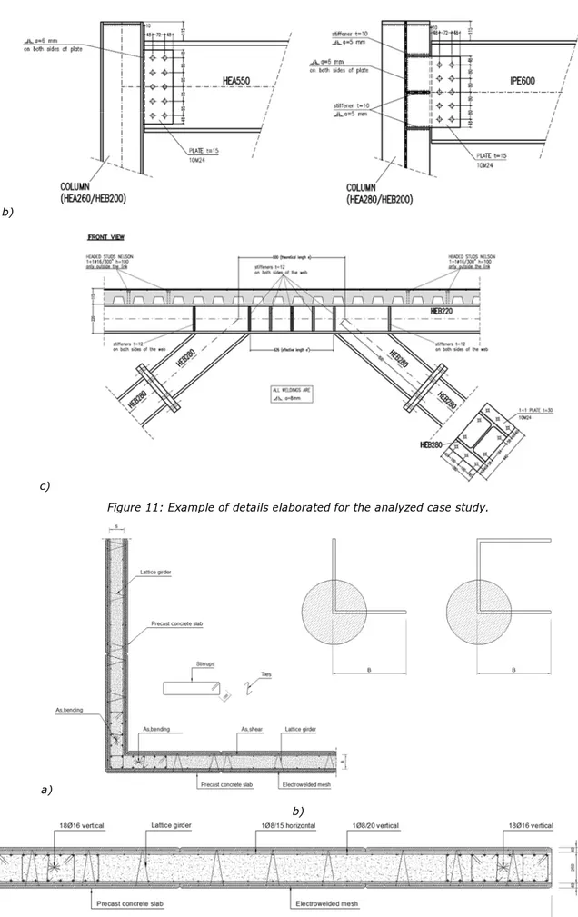
The proposed methodology and its application to the case study buildings can be found in TS and WE and in the corresponding deliverables D.1.1 and D.1.2. Examples of executive drawings are presented in Figure 11 for the case study with EBF and in Figure 12 for the case study with r.c. precast shear wall.
16
b)
c)
Figure 11: Example of details elaborated for the analyzed case study.
a)
b)
Figure 12: a) Corner structural detail for r.c. wall bracing system and plan configurations (top view), b) Technical drawing for r.c. wall (study case n°1, dissipative devices coupled with r.c. walls).
17
Comparison of proposed bracing systems for composite commercial buildings
A detailed comparison of the proposed solutions (steel braces vs. r.c. precast walls) from a technical and economic point of view has been executed, in terms of both influence area and total/unitary costs, varying geometrical parameters (span length, height, entity of seismic action) and ductility class selected for the design. Predalle floor systems, always resulting more convenient than steel sheeting floor, were assumed.
The cost model already elaborated in PrecaSteel project [1] has been updated to the current year considering both price analysis and official price lists of the public administrations (Table 1) coming from different countries (Italy - Southern Europe; Germany - Central Europe).
Table 1: Update of unit construction costs (Italy - Southern Europe; Germany - Central Europe).
ITEM Unit. cost U.M. NOTE
Concrete for r.c. walls (without
formwork) 322.22 €/m3 C25/30, XC2, S4
Concrete for r.c. slabs (without
formwork) 222.22 €/m3 C25/30, XC2, S4
Steel for r.c. structures 1.90 €/kg
Precast double plate r.c. walls 23.25 €/m2 Included cost of lattice girders, electro-welded meshes and assembling. Excluding fresh concrete
cast in place
Precast r.c. floor (Predalle) 32.99 €/m2 Unpropped solution
Steel sheeting composite floor 54.57 €/m2 Unpropped solution
Steel for frame structures 2.74 €/kg S355, included surface treatments, erection, bolted and welded joints
The wide dissertation regarding the comparison is presented in the TS and WE related to the commercial building with precast r.c. walls.
As a general remark, r.c. walls solutions are almost always (96%) competitive towards CBF systems for what concerns the dissipative capacity. This consideration is almost valid also comparing r.c. walls and EBF systems, characterized by a high capacity to dissipate seismic energy towards a more limited application. From a structural point of view, vertical loads can compromise the optimal dissipative behavior of link: to solve this problems, in EBF the decoupling of beams for gravitational loads and link is often executed. On the other hand, r.c. shear walls are able to sustain vertical load during the earthquake without compromising their dissipative capacity, resulting in a wider versatility application. An example of the executed comparisons is presented in Figure 13.
18
1.1.5 Steel-concrete commercial building with enhanced passive dissipative system The design of a steel-concrete commercial building with the introduction of the steel self-centering device (SSCD) developed, realized and experimentally tested inside PrecaSteel [1] and SteelRetro [3] has been proposed inside Steel-Earth (Figure 14). The adoption of such systems allows to reduce the residual displacements affecting the building after a seismic/cyclic event, decreasing the damages to non-structural elements and the following interruption of ordinary activities. Respect to traditional dissipative systems, self-centering devices present lower energy dissipation but the recovering of displacements (Figure 15). In the SSCD system, the dissipative capacity is devoted to specific low-yielding strength elements while the re-centering behaviour is due to the presence of pre-tensioned cables; the behaviour of the proposed system has been deeply investigated (Braconi et al. 2012 [16]) also in relation to the results of experimental tests executed on real scale prototypes.
Figure 14: Main components of the proposed system.
a) b)
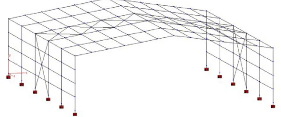
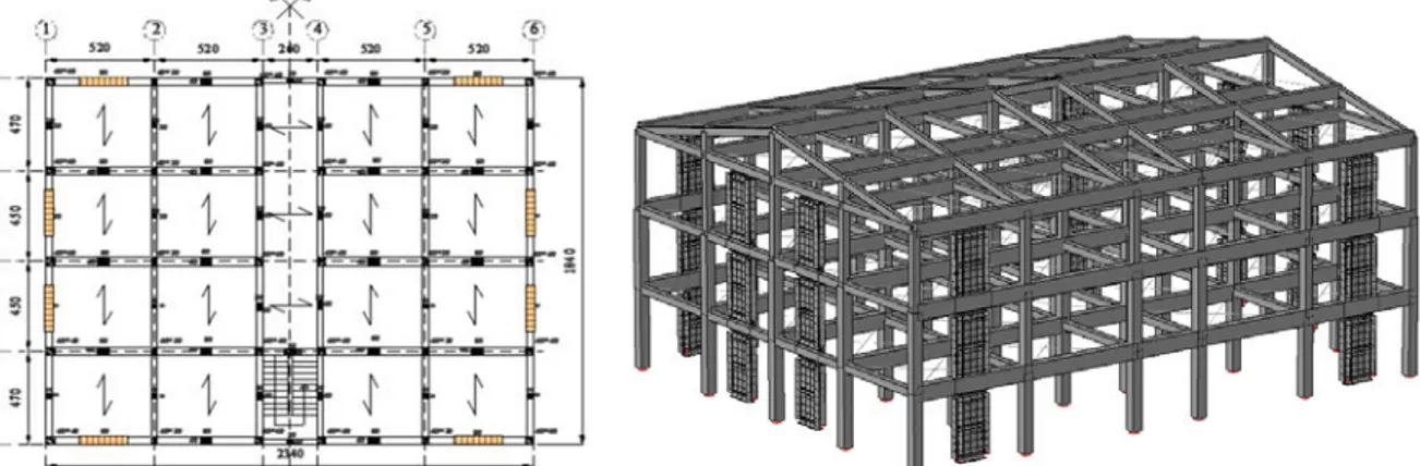
Figure 15: Ideal seismic response of a) an elasto-plastic dissipative system; b) self-centering device. Since current standards do not provide specific indications for the design of such systems, in the TS/WE a procedure is proposed for the application of the SSCD to a commercial case study building, based on the adoption of nonlinear methodologies. Also in this case, the decoupling of the structural behaviour has been adopted (Figure 16): r.c. shear walls, positioned in correspondence of the four corners, are designed to face the horizontal seismic action while internal steel pinned frames have been sized to resist gravitational loads; the connection between the r.c. walls and the steel frames is executed through SSCDs, responsible for the re-centering and dissipative capability of the designed building.
Figure 16: Three dimensional schematization of the case study building.
Seismic Action Displacement Elastio plastic Hysteretic dissipated energy Elastic sytem Max response Residual displacement Seismic Action Displacement Elastic sytem Max response NO Residual displacement Self-centering sytem
19
The design methodology to be adopted can be summarized as follows, with some steps that are common with the other design approaches.
[1]
Determination of the geometry of the building: plan and elevation geometry, number ofspan, span length, height of the building.
[2]
Determination of design action and load combinations: acting loads have been evaluatedaccording to Eurocode 1([6][11]) and Eurocode 8 [5].
[3]
Material selection: steel grades and concrete class shall be selected in agreement withstandards’ prescriptions. The main remark is related to the material selected for the dissipative elements of the SSCD device (i.e. low yielding steel).
[4]
Pre-design of structural elements: since no specific indications are given by technicalstandards, steel frames have been designed considering only vertical gravitational loads. The r.c. shear walls have been designed considering the horizontal seismic action adopting a behaviour factor q equal to 1.0: this means SSCDs behave as “rigid components” that do not dissipate the seismic action and transfer it as a whole directly to the walls.
[5]
Preliminary linear modelling and analysis: linear static and dynamic analyses shall beexecuted on a 3D model of the building. To minimize lateral displacements, the parameters constituting the SSCD (i.e. length, dimensions of the dissipative elements, diameter of pre-tensioned cables, …) have been modified to obtain a specific “deformed-shape configuration”, like the one presented in Figure 17: this allows to reduce relative displacements among different floors.
Figure 17: Desired modal deformation.
[6]
Determination of limit state conditions: two performance levels have been established todescribe the behaviour of a building with introduced SSCDs, in relation to the theoretical behaviour of the system (since no indications are provided by current standards). The ULS has been defined in relation to the axial deformation of the SSCD systems (higher than the maximum allowed elongation), corresponding to the yielding condition of pre-tensioned cables and the loss of re-centering capability; the SLS is associated to the achievement of the maximum interstorey drift able to guarantee the effective use of the building.
[7]
Nonlinear modelling and analysis: non-linear dynamic analyses (Figure 18) have beenexecuted on the developed model (with specific simplified relationship to simulate the dissipative/re-centering behaviour of the SSCD necessary to implement such devices in the model) in order to “optimize” the structural performance towards both ULS and SLS.
[8]
Evaluation of the parameters’ influence: the execution of IDA with different accelerogramshas allowed to define the most influencing parameters affecting the behaviour of buildings with introduced SSCD. In particular, analyses evidenced the effect of the length of the system, of the diameter of pre-tensioned cables, of the size of dissipative members and of a combination of such parameters on both the dissipative and re-centering behaviour of the building.
20
a)
b)
21
1.2 Retrofit of existing buildings
In WP1 Technical Sheets (TS) and Working Examples (WE) dealing with retrofit approaches for existing r.c. and masonry buildings in seismic area, mainly adopting steel-based devices, have been developed.
The TS represent a useful tool for designers and engineers that are guided in the evaluation of the efficacy of the proposed techniques considering technical, economic and feasibility aspects. A general description of the proposed technique is provided in the introduction of each TS, explaining the main benefits in the adoption of the system, its disadvantages as well as a general overview of the actual diffusion/application inside and outside Europe. The corresponding WE provide fully developed practical applications to existing case study buildings, showing in details all the steps to be followed for the rehabilitation interventions.
The produced documentation, globally collected in deliverables D.1.1 and D.1.2 and in the proceedings of the final workshop of Steel-Earth project, constitutes a potential instrument for designers, engineers and design companies involved in the retrofit of existing buildings.
Indications for the retrofit of vertical elements, horizontal floors, roof systems and foundations in both r.c. and masonry buildings, adopting traditional approaches as well as introducing steel-based innovative systems (braces, steel shear walls and enhanced passive dissipation systems, BRB, etc.) in relation to the performance levels that want to be achieved as a function of the seismic hazard, of the intensity of horizontal action, of the accepted criteria for structural safety, etc. are provided. All the TS (and the corresponding WE) follow the retrofit procedure elaborated inside SteelRetro project [3], that is a modification of the Performance Based Seismic Design (PBSD) for the application to existing buildings, briefly summarized in the steps below.
[1]
Survey of existing constructions and determination of the structural vulnerabilities (at dot,local and global level), in line with what foreseen by current standards.
[2]
Application of the PBEE methodology (i.e. Performance Based Earthquake Engineering),joining together design strategy, definition of the hazard model, modelling techniques, simulation method, definition acceptance criteria (i.e. FEMA 356 [17] and EN1998 [5]), analysis of technical and economic aspects.
[3]
Pre-selection of the most common retrofit techniques (also not steel based) that can beadopted for the considered existing building; determination of those ones that are not convenient and consequently neglected (due to accessibility, difficulty level for applicability, manpower skill for in-field works, demolition, previous technical evidences…). This step can be executed in agreement with the definition of a matrix approach (Table 3, Table 4), as proposed in SteelRetro [3].
[4]
Application of the selected rehabilitation technique(s) to the existing case study building:modelling and structural analysis of the existing retrofitted construction. The use of graphic methodologies, such as the N2 method ([18], [19]) or the Capacity Spectrum Method (ATC40 [20]), allow to directly evaluate the efficiency of proposed solutions and the design of eventual improvements.
[5]
Analysis of the structural response of the retrofitted foundation system with evaluation ofthe required bearing capacity and executive design of the adopted system.
[6]
Analysis of the structural response of the retrofitted superstructure (vertical andhorizontal/floor systems) and eventual optimization of the retrofit approach.
[7]
Design of connections and details, especially in the case of new resisting systemsconnected to the existing retrofitted structure.
The procedure above summarized is described as a general approach for all the considered applications in the TS, while its practical application is introduced inside the corresponding WE.
Table 2: Summary of possible vulnerabilities in existing buildings.
BUILDING SUMMARY: building type, location, age of construction Vulnerability
Type Description Structural sub-system Critical zones and elements involved Limit state D/C
DOT e.g. shear failure in the wall near the openings
e.g. vertical resisting system (localization)
e.g. type "a" critical zone (openings), class "2" collecting element (wall)
e.g. Limit State of Damage Limitation e.g. 1,5 LOCAL e.g. out-of-plane failure of the wall with failure of the wall-to-wall connections
e.g. vertical resisting system (localization)
e.g. type "b" critical zone (wall connections), class "2" collecting element (wall), type "I" transferring zones (wall-to-wall connections) e.g. Life Safety Limit State e.g. 2,1
22
GLOBAL
e.g. failure of the corner between two orthogonal walls with following failure of the roof system
e.g. vertical resisting system and roof system (localization)
e.g. type "a" critical zone (openings), class "2" collecting element (wall), type "I" transferring zones (wall-to-wall and roof-to-wall connections) e.g. Collapse Prevention Limit State e.g. 1,3
Table 3: Decisional Matrix condensing all relevant aspects for a preliminary judgment of the structural intervention technique. Legend for scoring L = low, M = medium, H =
high; Mark – L (5-6), M (7-8), H (9-10).
Structural aspects LMH Mark
Capability to achieve requested performance objective (after building evaluation!)
Compatibility with the actual structural system (no need of complementary strengthening or confinement measures) Adaptability to change of actions seismic typology (near field, far field, T<>Tic, etc.)
Adaptability to change of building typology
Technical aspects LMH Mark
Reversibility of intervention Durability
Operational
Functionally and aesthetically compatible and complementary to the existing building
Sustainability Technical capability
Technical support (codification, recommendations, technical rules) Availability of material/device Quality control
Economic aspects LMH Mark
Costs (material, fabrication,
transportation, erection, installation, maintenance, preparatory works)
Table 4: Typological form to be adopted with the decisional matrix in the preliminary selection of intervention technique – form filled for ring beam
technique for roof in masonry building.
Typological analysis of intervention (horizontal and vertical)
Technique classification Non-structural properties Stiffening Yes/No Amount of materials:- Strength Yes/No Technological aspects: -
Ductility Yes/No Used space: -
Structural classification Demolition: -
Masonry: Accessibility: -
Reinforced concrete Reversibility: -
Maintenance: -
1.2.1 General indications for the retrofit of existing buildings
In the TS/WE “General principles for seismic rehabilitation of masonry and r.c. buildings” general indications for the retrofit of existing r.c. and masonry constructions are provided.
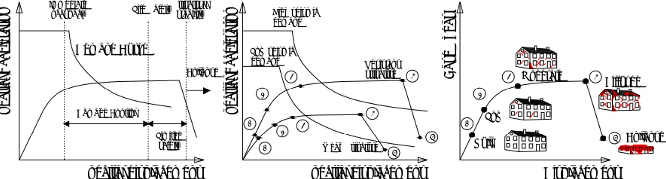
Current standards for constructions (D.M.14/01/2008 [21], EN1998-3:2005 [22], FEMA356 [17]) provide a codified procedure for the planning of readjustment/improvement operations for existing buildings. The adopted procedure is based on a deep investigation of the state of art the structure, achieved through structural and geometrical surveys, critical historical analyses and determination of the material mechanical properties. The PBEE approach foresees the execution of safety checks of the actual structural condition of the building, determining the dot/local/global vulnerabilities of the building in relation to whom the retrofit can be organized. Different solutions exist to reduce the seismic vulnerability of ancient constructions, in relation to structural typology, material, damage level and so on; the retrofit strategy can prescribe the increase of the strength, of the ductility, of the dissipative capacity or of a combination of them (Figure 19).
23
Figure 19: Structural performance: damage levels in relation to the force/displacement behaviour and in relation to seismic demand.
Retrofit mainly consists in modifying the demand/capacity ratio to make single elements and whole structure able to satisfy the required safety levels (i.e. D/C ≤ 1.0). Two main general approaches can be then used:
1. Retrofit interventions able to reduce the seismic demand.
2. Retrofit interventions able to increase the capacity of the building.
The reduction of the demand (D) can be obtained decreasing the mass/loads of the building or by the introduction of an isolation system. Such systems, applied between the superstructure and the foundation, increase of the vibration period of the building, with the following decrease of the related spectral acceleration and of design forces. The increase of the vibration period leads, at the same time, to the increase of the global displacement demand, that is anyway concentrated in correspondence of isolators, opportunely designed to face such displacements.
Figure 20: Response spectra in acceleration and displacement for buildings with/without isolation devices. The increase of the capacity (C) can be exploited increasing the strength, the ductility or the dissipative capacity of the construction, referring to single structural elements or, otherwise, to the whole building.
The introduction of a new resisting system facing horizontal seismic actions can produce (if correctly designed) a significant increase of the structural capacity, in terms of strength, stiffness and ductility. The application of braces, for example, can lead to the global protection of the building, that remains in the elastic field for a fixed level of seismic intensity and/or is able to sustain a certain damage level if plastic deformations take place. Different bracing systems can be used: traditional passive braces, BRB, dissipative self-centering systems, steel shear walls and so on.
The application of all such typologies to existing r.c. and masonry constructions has been deeply explained, also with practical examples, in deliverables D.1.1 and D.1.2.
The above described retrofit techniques alter the “global” dynamic behaviour of the construction, due to the introduction of a new and different resisting structural system (isolators, bracings, r.c. walls, …); beside such modifications, local interventions of single elements (steel, r.c. or FRP jacketing, masonry injections,…) are frequently needed to reach D/C ≤ 1.0. Table 5 summarizes the possible dot/local vulnerabilities affecting r.c. and masonry buildings of horizontal floors and roof, vertical bearing system and foundation.
More details and information are presented in the TS/WE collected in deliverables D.1.1 and D.1.2.
Sp ectra l Acce lerat ion Immediate
occupacy Life SafetyStructuralstability
Demand Curve Collapse Damage Control Limited safety High seismic demand Low seismic demand Resistant structure Weak Structure 1 2 3 4 5 4 5 1 2 3 Spectral displacement Sp ectra l Acce lerat ion Displacement B a se S he ar 1 2 3 4 5 Null Low Moderate Diffused Collapse Spectral displacement Period Ac ce le ra tion T T increasing damping isolated
not isolated Period
D isp la ce ment T T increasing damping isolated not isolated
24
a) b)
c)
Figure 21: Example of bracing systems to increase the capacity of existing buildings: a) CBF, b) EBF, c) BRB. Table 5: Typical vulnerabilities (local) for r.c. and masonry buildings.
Structural system Vulnerabilities
Foundation r.c./masonry Insufficient flexural and shear strength of foundation elements, Insufficient axial strength (deep foundations), Inadequate size of foundation on poor soil with following subsidence and relative
otations Vertical resisting
system (for gravitational loads)
Masonry Poor quality of materials, Insufficient thickness of walls, Wide openings with irregular disposition, Inadequate connections between walls and storey slabs, Plan and elevation irregularities
r.c.
Longitudinal reinforcements insufficient or with insufficient overlapping length, Too high stirrup spacing, Insufficient anchorage length, Not adequate connections between columns and beams, Plan and elevation irregularities
Horizontal floors
and roof r.c./masonry
High deformability, Absence of adequate connections, Presence of relevant openings (stairs…), Plan irregularities
1.2.2 Indications for the seismic rehabilitation of the foundation system
The weaknesses of the foundation system shall be deeply analyzed, since of fundamental importance in assessing the performance of the structure as a whole. The foundation system and the subsoil shall be able to withstand pressures due to seismic load combination, providing adequate stiffness without compromising the functionality and the safety of the superstructure. The retrofit of existing foundations mainly consists in the increase of the strength and of the stiffness capacity, while no requirements are needed for the ductility capacity, designed to remain in elastic range. Different approaches exist for the retrofit of foundations, related to the improvement of the capacity of the system or, otherwise, to the decrease of the demand.
In agreement with §2, the general presented methodology is used to organize the retrofit of foundation systems. In particular, in the TS/WE “Seismic rehabilitation of foundations of existing
buildings” the application of micropiles as retrofit technique for an existing building is proposed.
For the pre-selection of the appropriate retrofit technique, the matrix approach proposed in SteelRetro [3], basing on general qualitative-marking criteria, can be used (Table 6).
25
Isolat ed sprea d foot ingsStrip footings Founda
tion of new el em ent s Mat found ation s Pile foundat ions Ac ce ss ibilit y and he ight restricti o ns Impose noise a n d vibrat ion Restrictions imposed by exis ting ut ilit ie s ( g as, water , su pp ly s yst em s) R estri ct io ns as soci ate d with on going operations
Spread footing enlargement or replacement Yes Yes Yes - - A S S S
Addition of a strap beam Yes Yes - - - A S S S
Addition of micropiles Yes Yes Yes Yes Yes NA M M M
Addition of shallow elements to deep foundations - - - - Yes A S S S
Addition of a driven Piles Yes Yes Yes Yes Yes NA M M M
Overlaying mat foundations - - - Yes - A S S S
Table 6: Suitability for foundation typologies in r.c. and main limitations for rehabilitation method; Yes – Possible to use method for strengthening; A – Applicable; NA – Not Applicable; SC – Special Car; M – Major; S
– Small; - None
The analysis of ground-soil characteristics is necessary to evaluate the mechanical properties and the stratigraphic profile of the significant part of the soil interested by the applied intervention; the
data regarding shear wave velocity (Vs), elastic shear modulus (G0), bond strength (qb) and
undrained cohesion (cu) are also needed to evaluate and, if necessary, to model the
soil-structure-interaction.
In the case of the introduction of micropiles to increase the strength of the existing system, for example, a correct array of piles shall be analyzed and studied (number, typology and disposition of micro-piles). Preliminary checks shall be executed to assess strength and buckling problems; modelling, analysis and safety verifications of the adopted solution are finally required to evaluated the influence of the retrofit technique on the structural safety of the whole construction.
More details and information are presented in the TS/WE collected in deliverables D.1.1 and D.1.2. 1.2.3 Indications for the seismic rehabilitation of vertical systems
The rehabilitation of vertical systems (i.e. vertical walls in masonry buildings, beams and columns/frames in the case of r.c. buildings) shall be pursued both in terms of strength and lateral stiffness, in agreement with safety requirements foreseen for ULS and SLS.
In the case of masonry buildings, vertical walls are the structural elements responsible for the lateral resistance: their seismic performance consequently governs the overall behaviour of the construction. The low seismic performance of masonry buildings is generally associated to the lack of ductility due to brittle materials and to the absence of seismic detailing able to guarantee the “box” behaviour. The failure of masonry panels usually takes place at low deformation and is associated with a large and sudden drop in lateral load resistance. In addition, the lateral/shear strength of the walls tends to degrade faster than their flexural strength with cycling loading. In the case of r.c. buildings columns and beams are responsible for the structural capacity of the whole construction; the adoption of MRF is usually associated to a high lateral deformability due to the reduced stiffness of the system. Existing r.c. buildings are often characterized by poor quality
of concrete (lower than 150 kg/cm2) and by the adoption of the scheme strong beam/weak
column, opposite to the one actually foreseen by modern seismic design standards to allow the development of global collapse modalities. Poor details of reinforcements and the absence of connections between perpendicular frames generate the high vulnerability to horizontal seismic action.
As a general remark, after the determination of vulnerabilities coming from the detailed analysis of the state of art of the building and the adoption of the matrix approach (following for example Table 3 and Table 4) for the pre-selection of retrofit techniques, the ones considered “more efficient” (from a technical and economic point of view) have been applied to the structural model of the existing building to evaluate their contribution.
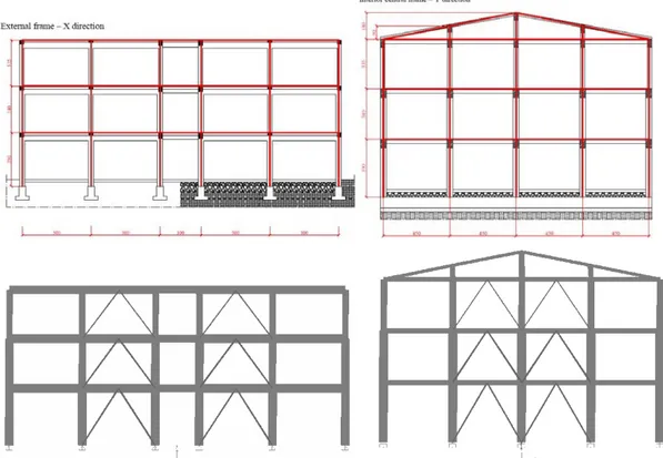
The application of a new resistant system, designed to face lateral horizontal actions and working in parallel with the existing structure, represents one of the best possibilities to improve the structural performance of the existing constructions. Figure 22 presents possible approaches for masonry buildings, consisting in the application of steel mesh able to increase the strength of the vertical walls, or in the introduction of additional resisting systems such as steel braces or an internal MRF frame. Figure 25 shows possible application of additional vertical steel bracing systems (including traditional passive braces and BRB) in r.c. existing frames.
26
Figure 22: Rehabilitation of masonry walls: with steel mesh and shotcrete, steel braces, MRF steel frame.
Figure 23: Example of retrofit of r.c. vertical structure with BRB and traditional bracing systems.
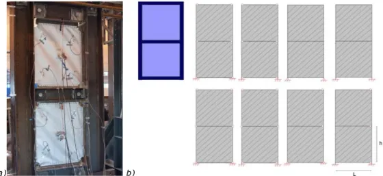
Numerical models of the existing case study buildings with application of the different analyzed retrofit techniques have been elaborated inside Steel-Earth to evaluate the efficacy of the proposed systems (Figure 24). Nonlinear analyses are suggested to compare the behaviour of the building before and rehabilitation: the N2 method ([18], [19]) allows to evaluate the structural efficiency of proposed techniques, comparing demand and capacity of the retrofitted structure and finally selecting the system that better satisfy the performance levels that want to be achieved (Figure 25). The analysis of the technical and economic feasibility is necessary to select the most appropriate retrofit approach, i.e. the evaluation of the benefits of application towards the intrinsic costs necessary for the installation. The final design of details and connections shall be accurately taken into consideration since the connection between the existing structure and the new resisting system cannot be easy to realize especially due to the poor quality of materials of the old construction.
Figure 24: FEM models for a) masonry building and b-c) r.c. frames with bracing system for retrofit.
a) b)