The shear mode of multi-layer graphene
P. H. Tan
1⋆, W. P. Han
1, W. J. Zhao
1, Z. H. Wu
1,K. Chang
1,
H. Wang
2, Y. F. Wang
2, N. Bonini
3†, N. Marzari
3‡,N. Pugno
4,5,
G. Savini
5, A. Lombardo
5, A. C. Ferrari
5⋆1State Key Laboratory for Superlattices and Microstructures, Institute of
Semiconductors, Chinese Academy of Sciences, Beijing 100083, China
2Department of Physics, Nankai University, Tianjin 300071, China
3Department of Materials, University of Oxford,Oxford OX1 3PH, UK
4Department of Structural Engineering and Geotechnics, Politecnico di Torino,
10129 Torino, Italy
5Engineering Department, Cambridge University, Cambridge CB3 OFA, UK
⋆e-mail: [email protected]; [email protected]
† Present Address: Department of Physics, King’s College London, Strand,
London WC2R 2LS, UK
‡ Present Address:Theory and Simulation of Materials, cole Polytechnique
Fdrale de Lausanne, 1015 Lausanne, Switzerland
The quest for materials capable of realizing the next generation of electronic and photonic devices continues to fuel research on the electronic, optical and vibrational properties of graphene. Few layer graphene (FLG) flakes with less than 10 layers do each show a distinctive band structure. There is thus an increasing interest in the physics and applications of FLG. Raman spectroscopy is one of the most useful and versatile tools to probe graphene samples. Here, we uncover the interlayer shear mode of FLGs, ranging from bilayer-graphene (BLG) to bulk graphite, and suggest that the
cor-responding Raman peak measures the interlayer coupling. This
low energy makes it sensitive to near-Dirac point quasi-particles. Similar shear modes are expected in all layered materials, provid-ing a direct probe of interlayer interactions.
Single Layer Graphene (SLG) has high mobility and optical transparency, in addition to flexibility, robustness and environmental stability[1, 2]. These intriguing properties extend to multi-layers. Bilayer graphene (BLG) is a tunable band gap semiconductor[3], tri-layer graphene (TLG) has a unique electronic structure consisting, in the simplest approximation, of massless SLG and massive BLG subbands[4, 5, 6]. Few layer graphene (FLG) with less than 10 layers do each show a distinctive band structure[6]. There is thus an increasing interest in the physics of FLGs, with or without Bernal stacking[7, 8, 9], and their application in useful devices. For example, since SLG absorbs 2.3% of the incident light[10], FLG can be used to beat the transmittance
of Indium Tin Oxide(∼90%)[2], and to engineer near-market transparent
conductors[11], exploiting the lower sheet resistance afforded by combining more than one SLG[2, 11]. The layers can be stacked as in graphite, or have any orientation. This gives rise to a wealth of electronic properties, such as the appearance of a Dirac spectrum even in FLG[12].
Raman spectroscopy is one of the most useful and versatile tools to probe graphene samples[13, 14]. The measurement of the SLG, BLG, and FLG Raman spectra[13] triggered a huge effort to understand phonons, electron-phonon, magneto-phonon and electron-electron interactions, and the influ-ence on the Raman process of number and orientation of layers, electric or magnetic fields, strain, doping, disorder, edges, and functional groups[14].
The SLG phonon dispersions comprise three acoustic and three optical branches. A necessary, but not sufficient, condition for a phonon mode to be Raman active is to satisfy the Raman fundamental selection rule, i.e. to
be at the Brillouin Zone centre, Γ, with wavevector q≈ 0[15]. SLG has six
normal modes at Γ: A2u+ B2g + E1u+ E2g[16]. There are two degenerate
in-plane optical modes, E2g, and one out-of-plane optical mode B2g[16]. E2g
modes are Raman active, while B2g is neither Raman nor IR active[16]. In
the case of graphite there are 4 atoms per unit cell, and only half of them have fourth neighbors that either lie directly above or below in adjacent layers. Therefore the two atoms of the unit cell in each layer are now inequivalent. This doubles the number of optical modes, and is responsible for the IR activity of graphite[16]. All SLG optical modes become Davydov-doublets in graphite: E2g generates a IR active E1u and a Raman active E2g, B2g
-80 -40
0
40
80
In te ns ity (A rb . U ni ts )0
1
2
3
4
5
6
Raman Shift (cm
-1)
0
20
40
60
0
1
2
3
4
Raman Shift (cm
1550 1625
-1)
2550 2700
In te ns ity (A rb . U ni ts ) 0 25 50 75C
C (e1)
G
2D
(e2)
2LG-B 11LG-Bbulk
(d1)
G
2LG-A 11LG-Abulk
2LG-A 11LG-A2D
X1/5
C
C
(c)
(d2)
C
C
5
µm
2LG
11LG
2LG-B
.
.
11LG-B
2LG-B 11LG-B.
11LG-A
2LG-A
.
-50 0
50
500 550
In te ns ity (A rb . U ni ts )1550 1600 1650
In te ns ity (A rb . U ni ts )(b1)
(b2)
X1/10
X1
X1/240X1/20
X1/10
X1/12 C C 3LG 3LG Si Gunpolarized
X4
polarized
(a)
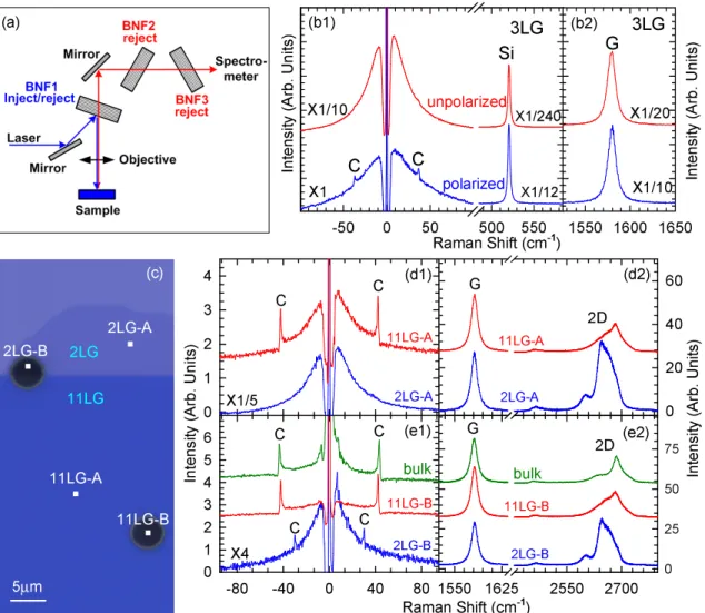
Figure 1: Raman set up and spectra of supported and suspended
multilayers. (a) Schematic diagram of our single monochromator with three
BragGrate notch filters (BNF). (b1)Unpolarized and polarized Raman
spec-tra of 3LG on SiO2/Si(001) in the C peak region and (b2) in the G peak
region. (c) Optical micrograph of FLG sample. A/11LG-A and 2LG-B/11LG-B denote supported and suspended flakes, respectively. (d1) S/AS spectra of supported flakes in the C peak region. (d2) S-spectra of supported flakes in the G/2D peaks region. (e1) S/AS spectra of suspended flakes in the C peak region. (e2) S-spectra of suspended flakes in the G/2D peak region
goes into an IR-active A2u, and an inactive B2g. The zone boundary acoustic
modes fold back to the zone centre as rigid layer modes: an optically inactive
B2g and a Raman active E2g. The acoustic modes remain E2u and E1u[16].
Thus for graphite[16, 17] Γ = 2(A2u+ B2g + E1u+ E2g). There are now two
Raman active E2g modes, each doubly degenerate. The high frequency E2g
mode is responsible for the well-known G peak, measured and discussed in thousands of papers to date for any carbon allotrope[18].
Here we focus on the low energy E2g mode. This is a doubly degenerate
rigid layer shear mode, involving the relative motion of atoms in adjacent planes. It was first measured in 1975 by Nemanich et al.[19] in bulk graphite at∼42cm−1. We uncover the equivalent mode for FLGs, and show that it provides a direct measurement of the interlayer coupling. For this reason we name C the corresponding Raman peak. On one hand, the C peak energy, E(C)∼5meV, is much lower than the notch and edge filter cuts of most Raman spectrometers, and its intensity is much smaller than the G peak. This explains why it was not seen thus far in FLG and, even for graphite, it was reported only in an handful of papers[19, 20, 21], with no firm agreement on position and width. On the other hand, this makes it a probe of the quasi particles near the Dirac point by quantum interference.
The traditional approach to perform very low energy Raman measuments involves the use of a triple spectrometer. However, this massively re-duces the signal intensity compared to the combination of a single monochro-mator and a notch filter, while the latter arrangement usually does not allow
to detect modes below∼30-40cm−1. Here we show that detection of Raman
modes down to∼10cm−1is possible by utilizing three BragGrate notch filters (BNF) combined with a single monochromator, as schematized in Fig.1(a). This set-up is simple, relies on commercial components, and enables us to get good signals with low excitation power and short acquisition times (see Methods for details).
The easiest way to get high quality FLG is by graphite exfoliation[22] on SiO2/Si, to enhance visibility[23, 24]. Often the Si is doped, to be used
as back gate[22]. However, this poses a problem for low frequency Raman measurements. The incident light can excite carriers in doped Si, produc-ing a strong background[25], that can overshadow the signal of FLG with less than 6 layers. One approach to overcome this issue is to perform polar-ized Raman measurements, since this background is strongly suppressed in cross polarization[25]. Fig.1(b) shows the unpolarized Raman spectrum (top graph) of 3LG on SiO2/Si(001), as well as the polarized one (bottom graph)
with incident light along [1 -1 0] and scattered light analyzed along [1 1 0]. A large substrate background is observed in the unpolarized measurement, while in the polarized one the Si mode and its low-frequency background
are suppressed, thus revealing a peak∼37cm−1. However, polarized Raman
spectra have lower intensity, and a different 2D to G ratio compared to un-polarized ones. Thus, in order to collect the highest quality C peak data in unpolarized measurements, we take a different avenue. We use low doping
Si (resistivity≥2000Ω.cm) and suspend the FLG on∼2-5µm holes, as shown
in Fig.1(c). The number of layers and their stacking are identified by a com-bination of 2D peak Raman spectroscopy[13, 7] and optical contrast on the supported section of the flake[23, 24]. Figs.1(d,e) plot the Stokes (S) and Anti-Stokes (AS) spectra for supported and suspended BLG, 11LG and bulk graphite. We use the notation NLG to indicate FLG with N layers. Thus 1LG=SLG; 2LG=BLG, 3LG=TLG, while, e.g., 11LG means 11 layers. In the suspended flakes the C peak is clearly seen. On the other hand, the sup-ported ones show the Si background, Fig.1(d1). While for 11LG and bulk this does not overshadow the C peak, for fewer layers this covers the C peak, to the point that for supported BLG it is difficult to detect the C peak for unpolarized measurements.
We calibrate the C peak position, Pos(C), as follows. We first set the
Rayleigh line as 0cm−1. Given the low E(C), the S/AS intensity ratio is
close to 1. Similar to the G peak[26], but unlike D and 2D peaks[26], the S/AS C peaks are symmetric relative to the Rayleigh line, thus we take
Pos(C)=[Pos(C)S+Pos(C)AS]/2. We get Pos(C)∼31cm−1for BLG;∼42.7cm−1
for 11LG and∼43.5cm−1 in bulk graphite. By assuming a lorentzian
line-shape, we derive a Full Width at Half Maximum, FWHM(C),∼1.2cm−1.
Considering the∼0.5cm−1 spectral broadening of our spectrometer, we derive an intrinsic linewidth∼0.7cm−1. From the S/AS ratio we estimate the local T on the sample as[15], T = ~ω/kBln{I(C)S/I(C)AS· {[ωL+ P os(C)]/[ωL−
P os(C)]}4}, where ~ is the reduced Planck constant, ωLis the laser frequency,
kB is Boltzmann constant, I(C)S/I(C)AS is the C peak S/AS intensity ratio.
This gives T∼300K, indicating negligible laser heating.
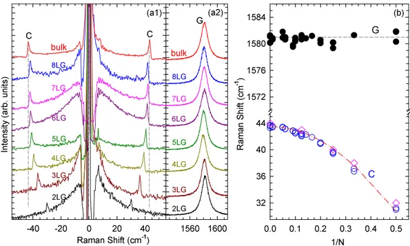
Figs.2(a1,a2) plot the Raman spectra for a set of samples of increasing thickness. Fig.2(b) shows the fitted Pos(G) and Pos(C) as a function of
1/N, where N is the number of layers. While Pos(G) stays∼1581cm−1 with
no significant change with N, Pos(C) increases from BLG to bulk graphite. Note that in Fig.2(b) the spectral range used to plot the G and C peak data is the same (16cm−1), thus the C peak shift with N is truly representative
Raman Shift (cm-1) -40 -20 0 20 40 Int en sit y ( arb . u nit s) (a1) C 1560 1600 1/N 0.0 0.1 0.2 0.3 0.4 0.5 Ra ma n S hif t (c m -1) 32 36 40 44 1572 1576 1580 1584 (a2) C 3LG 4LG 5LG 6LG 8LG bulk 7LG 3LG 4LG 5LG 6LG 8LG bulk 7LG G G (b) C 2LG 2LG
Figure 2: Raman spectra and fits of the C and G peaks as a
func-tion of number of layers.(a1) S/AS C peak spectral region.(a2) G peak
spectral region.(b) Pos(G) (solid black circles), Pos(C) (open blue circles), as a function of inverse layer number. The red dash-dotted line is a plot of Eq.3, open diamonds are DFT calculations. Vertical dashed lines in (a1) and the horizontal line in (b) are guides to the eye.
of its much stronger variation when compared to G. I(C)/I(G) at 633nm, after calibration to take into account the different response of our system in
the C and G peak spectral regions,is∼0.0052, 0.044, 0.049 for BLG, 11LG
and bulk graphite, while the ratio of integrated peak areas, A(C)/A(G), is∼0.00038, 0.0023, 0.0034. These slightly change with excitation energy,
e.g., I(C)/I(G)∼0.025 and A(C)/A(G)∼0.00096 for bulk graphite at 532nm.
Since these ratios depend on the Electron Phonon Coupling (EPC), this immediately indicates that EPC(C) is much smaller than EPC(G).
The Pos(C) dependence on the number of layers can be explained con-sidering a simple linear-chain model. For FLG with N layers, there are 2N atoms per unit cell. The corresponding in-plane optical modes consist of N degenerate pairs of in-pane stretching modes, and N-1 degenerate pairs of in-plane shear modes between neighboring layers. We assume that a layer
interacts strongly only with adjacent layers and that the strength of this interlayer coupling is characterized by an inter-layer force constant per unit area, α. The N-1 shear modes of a NLG can be computed by diagonalizing
the corresponding N× N (tridiagonal) dynamical matrix. The frequency ωi
(in cm−1) of the i-th vibrational mode is given by:
ωi2 = 1 2π2c2 α µ { 1− cos [(i− 1)π N ]} (1)
where i=2,...N. µ=7.6×10⁻²⁷Kg/˚A2 is the SLG mass per unit area, c the
speed of light in cm/s. The corresponding i-th displacement eigenvector v(i)j is given by: v(i)j = cos [(i− 1)(2j − 1)π 2N ] (2) where j labels the layers. The highest frequency mode (for i=N) is Raman-active. Here adjacent layers move out-of-phase in the direction parallel to
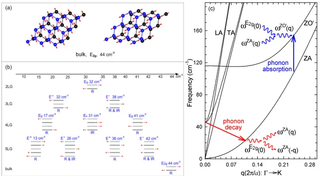
the planes. In the case of graphite N → ∞ and ω∞= P os(C)∞= πc1 √α/µ.
This is the doubly degenerate E2g shear mode responsible for the C peak, see
Fig.3(a). Thus, Pos(C)N (in cm−1) for a NLG is given by Eq.1 setting i=N:
P os(C)N = 1 √ 2πc √ α µ √ 1 + cos (π N ) (3) In BLG, N=2, and Pos(C)2 = √2πc1 √
α/µ, i.e. √2 smaller than Pos(C)∞, cor-responding to bulk graphite, in excellent agreement with the experiments. In fact, the dash-dotted line in Fig.2(b) shows that Eq.3 describes all the experi-mental data, thus validating our simple model. The only unknown parameter in Eq.3 is the interlayer coupling strength. By fitting the experimental data
we can directly measure it. We get α ∼12.8×10¹⁸N/m3. This implies that,
in Bernal stacked FLG, the C mode hardening is not due to a variation of interlayer coupling, but rather to an increase of the overall restoring force (surface layers are less bound than in the bulk) going from BLG to bulk graphite. For a given N, we expect variations of Pos(C) if the interlayer cou-pling is modified, e.g. by changing the spacing or relative layer orientation (in the latter case we also expect mode splitting).
These results are further confirmed by ab-initio calculations performed using density functional theory (DFT) and density-functional perturbation (DFPT) theory as discussed in Methods.
q(2π/a): Γ K 0.00 0.07 0.14 0.21 0.28 Fr eq ue nc y ( cm -1) 0 40 80 120 160 LA TA ZA ZO' ωE 2g(0) ωZA (q) ω ZA(q) ωE 2g(0) (c) ω ZA(-q) phonon decay phonon absorption ωZO' (q)
Figure 3: Normal mode displacements and anharmonic decay
chan-nels.(a) The two degenerate E2g modes in graphite.(b) Symmetry, ab-initio
frequencies and normal mode displacement for each shear mode. The Raman (R) and infrared (IR) active modes are identified. (c) Schematic representa-tion of the anharmonic decay channels for the C mode in bulk graphite.
Fig.3(b) plots the in-plane shear modes for 2-5LG and bulk graphite. For a given N, there are N-1 shear modes, either Raman or IR active or both, but, for N>2, N-2 of those have a different displacement pattern compared to the C mode, since not all the neighboring layers vibrate out-of-phase. The highest frequency Raman active mode corresponds to the C peak. We expect the other Raman active modes to have a much weaker intensity compared to the C peak, as a result of a smaller EPC, also confirmed by DFT. More work is needed to detect those modes.
We get an excellent agreement between our DFT frequencies and the ex-perimental data, as indicated by the open symbols in Fig.2(c). This might seem surprising, since local or semi-local exchange correlation functionals may not properly describe Van Der Waals interactions[27], and more so-phisticated approaches are necessary to accurately describe the interlayer bonding and equilibrium distance in graphitic materials (see[28] and
refer-ences therein). However, it was shown that in bulk graphite all phonon dispersions are well described by DFT, both in LDA and in the generalized gradient approximation (GGA), even in absence of VdW interactions in the functional, provided that the correct geometry (i.e. interlayer spacing) is used[29]. This occurs because VdW interactions can give a significant con-tribution to the total energy (hence determining ratio, R, between interlayer spacing and in-plane lattice constant), but give a negligible contribution to second derivatives (i.e. the phonons). Thus, if the correct geometry is used, phonon dispersions are well reproduced. LDA does provide excellent geome-tries: in graphite R=2.725, 2.74, 2.91, as derived from experiments, LDA and VdW-DFT, while for BLG, LDA and VdW-DFT give R=2.74, 2.90. LDA consistently predicts a smaller value than VdW-DFT, but in excellent agree-ment with experiagree-ments. This is confirmed, independently, for bulk graphite and any FLG, by the very good agreement between our LDA calculations and the measured FLG C modes. It is also important to stress that both LDA and VdW-DFT predict the same interlayer spacing for AB stacked systems. This is consistent with our interpretation that the C mode hardening when going from Bernal stacked BLG to graphite is not a result of a variation of the interlayer distance and coupling strength with the number of layers.
Our measured α gives further physical insights in FLG. We note that α is a shear force per unit area. Thus, by definition of shear force, F = αAx, where
A is the graphene surface area and x is the shear displacement. According
to classical definitions in elasticity[30], we also have that the mean shear stress is τ = F/A and, for small displacements, the mean shear strain is
γ = x/t, where t is the equilibrium distance between two adjacent graphene
layers. Also, by definition, the shear modulus of the layer-layer interface is
C44 = τ /γ. Thus, α is linked to the shear modulus as: C44 = αt. From
our measurements we get C44=4.3GPa for graphite, consistent with previous
reports giving values between 4.5 and 5.1GPa[31, 32]. On the other hand, the C peak allows for the first time to probe the shear modulus for FLG of any number of layers. This analysis could be extended to any layered material, deducing the corresponding elastic constants still unknown.
Since the C peak corresponds to a E2g mode at Γ, it is not expected to
be dispersive with excitation energy, unlike the D, D’, D” peaks and their overtones[14]. This is proven in Fig.4a, where the C peak does not shift for three excitation wavelengths: 785,633 and 532nm.
We now consider FWHM(C). Two factors contribute to the linewidth
Raman Shift (cm-1) 30 40 50 60 Int en sit y ( arb . u nit s)
(a)
bulk, 532nm
(c)
3LG, 633nm
M<-K->Γ(1/A) -0.008 -0.004 0.000 0.004 0.008 En erg y ( me V) -10 -5 0 5 10 E(C)3LG
bulk, 785nm
bulk, 633nm
1/N 0.0 0.1 0.2 0.3 1/ q -0.4 -0.3 -0.2 -0.1 0.0 1/N 0.0 0.1 0.2 0.3 Γ (c m -1) 0.0 0.3 0.6 0.9 1.2(b1)
(b2)
Figure 4: BWF lineshape of the C peak. (a) C peaks with BWF fit for bulk graphite and 3LG. Fitted curve (solid red lines); background (Dashed
lines); BWF component (dash-dotted lines). (b1,b2) fitted 1/|q| and Γ as
a function of inverse layer number. Note that 0.5cm−1 was removed from
Γ to account for the system resolution. The dash-dotted lines are guides to the eye. (c) Schematic band structure of 3LG close to K. The gray regions highlight transitions near K that could resonate with the C mode. Red arrows indicate transitions with the same energy as the C mode, E(C).
and anharmonic phonon-phonon interactions[35]. In the absence of doping,
FWHM(G)∼12-14cm−1 in SLG and bulk graphite, mostly due to the
domi-nant EPC contribution[33, 34], the phonon-phonon one being∼1.7cm−1[35].
The experimental FWHM(C) is much smaller, not just compared to the overall FWHM(G), but also with respect to the non-EPC component of FWHM(G). This immediately indicates a much smaller EPC(C) than EPC(G), consistent with the much smaller C peak intensity. Our DFT calculations give
FWHM(C)∼0.3cm−1 at 300K in graphite, in reasonable agreement with
ex-periments, the EPC contribution being∼0.05cm−1, and the phonon-phonon
of the total anharmonic linewidth at 300K) and absorption (70%) processes. The shear mode splits mainly into two out-of-plane ZA bending modes, at q and -q, close to Γ. The absorption processes are dominated by the merging of the shear mode and a ZA mode into an out-of-plane ZO’ bending mode (the prime indicates an optical mode where the two atoms in each layer of the unit cell of graphite vibrate together, but out-of-phase with respect to the two atoms of the other layer), see Fig.3(c). We expect the anharmonic linewidth not to change significantly in NLG, since the available phase space of decay/absorption channels in these systems is very similar to graphite. Also, our calculations for BLG, TLG and 4LG show that the EPC contribu-tion to the linewidth is nearly independent of the number of layers. Thus, DFT indicates the overall FWHM not to change significantly with N, in agreement with experiments. Note that, if we take a 4LG as an example, the
EPC contribution to FWHM(G) is ∼150 times bigger than for FWHM(C).
In turn, this is ∼15 times bigger than the EPC contribution to the other
Raman active shear mode at∼17cm−1, confirming the expectation that the
other C modes would be challenging to detect.
We now examine more closely the C peak shape. This can be well fitted with a Breit-Wagner-Fano (BWF), as shown, e.g., in the case of 3LG and bulk graphite in Fig.4(a). In general, this arises as quantum interference between a Raman allowed phonon and a continuum of Raman active electronic (or multiphonon) transitions[36]. The BWF lineshape is given by[36]:
I(ω) = I0
[1 + 2(ω− ω0)/(qΓ)]2
[1 + 4(ω− ω0)2/Γ2]
(4)
where I0, ω0, Γ and 1/|q| are the intensity, uncoupled mode frequency,
broadening parameter and coupling coefficient. The peak maximum is at
ωmax=ω0+ Γ/2q, while its FWHM=Γ(q2+ 1)/|q2− 1|. In the limit 1/q→0, a
Lorentzian lineshape is recovered, with FWHM=Γ and ωmax=ω0. The fitted
1/|q| and Γ are summarized in Fig.4(b1,b2). Pos(C) in the BWF fit is Γ/2|q| (∼0.3cm−1) higher than in a Lorenzian fit.
We find a smaller 1/|q| when we use a laser power high enough to shift
the G peak, i.e. to heat the sample. Thus, in our low power experiments, the possible laser-induced electron-hole plasma is not the cause of the observed BWF lineshape. We also find that the C peak of bulk graphite at 77K has the same q as at room temperature, in contrast to what expected if the BWF would be due to a multiphonon resonance[37]. We thus attribute the BWF lineshape to quantum interference between the C mode and a continuum of
electronic transitions near the K point. The band structure of Bernal-stacked FLGs can be decomposed into groups of BLG bands, with different effective masses, plus- for odd layer numbers- a pair of SLG bands[6]. Fig.4(c) plots, as an example, a simplified band structure of 3LG in a range of the order of the C phonon energy, E(C), and identifies electronic transitions that can couple with the C mode. Because the density of states with energy higher than E(C) is much larger than that with energy smaller than E(C), q is not expected to change significantly from BLG to bulk graphite, in agreement with our findings. If the Fermi energy, EF, is larger than E(C)/2, the resonance with
the C mode would become weaker, eventually leading to the disappearance of
the BWF profile. Figs.4(b1,b2) show that 1/|q| and linewidth show a small
decrease with decreasing N. It is known that the top and bottom layers of NLG flakes can be doped by absorption of air molecules or charge transfer
from the substrate[38, 39, 34]. This would reduce the coupling between
the C mode and the transitions below 2EF. Therefore, the trend observed
in Figs.4(b1,b2) can be assigned to the higher influence of adsorbates and charge transfer for lower number of layers.
As discussed above, FWHM(G) is much larger than FWHM(C), due to the much larger EPC and phonon-phonon contributions. The EPC dominates FWHM(G), and the G peak is always lorentzian.
In summary, we uncovered the Raman signature of the interlayer shear mode of FLG. Graphite is not the only layered material. Transition metal dichalcogenides, transition metal oxides, and other compounds such as BN, Bi2Te3, and Bi2Se3 can also be exfoliated to produce a whole range of
two-dimensional crystals, that are just beginning to be investigated[40]. Similar shear modes are expected in all these materials, and their detection will provide a direct probe of interlayer interactions.
Methods
Raman spectroscopy Raman measurements are performed in backscat-tering geometry using a Jobin-Yvon HR800 Raman system, equipped with a liquid nitrogen cooled charge-coupled detector. The laser excitation wave-lengths are 785nm of a Ti-Sapphire laser, 633nm of a HeCNe laser and 532nm of a diode pumped solid-state laser, respectively. A typical laser power of 0.5mW is used to avoid sample heating. The laser plasma lines are removed using a BragGrate bandpass filter, since those would appear in the same
spectral range as the C peak. The Rayleigh line is suppressed by using three BragGrate notch filters with optical density 3, and with a spectral
bandwidth∼5-10cm−1. The configuration of three BragGrate notch filters in
the Jobin-Yvon HR800 spectrometer is schematized in Fig.1(a), but a similar arrangement can be implemented for other spectrometers. Ar gas is flown on the sample to remove the low-frequency Raman modes from the air. We
use a 100× objective with NA=0.90. A 1800 lines/mm grating enables us to
have each pixel of the charge-coupled detector cover∼0.35cm−1 at 633nm. A
spectral resolution ∼0.6cm−1 is estimated from the FWHM of the Rayleigh
peak at 633nm.
Computational details Calculations are performed using DFT and DFPT, as implemented in the PWSCF package of the QUANTUM-ESPRESSO dis-tribution, within the Local Density Approximation (LDA), and ultrasoft pseudopotentials generated using the RRKJ approach. The cutoffs are 40Ry for the wave functions, and 480Ry for the charge density. The Brillouin zone
is sampled on a 42× 42 × 16 Monkhorst-Pack mesh for bulk graphite and
42× 42 × 1 for SLG and BLG. NLG are modeled using supercell configura-tions, with periodic replicas separated by 10˚A vacuum in the perpendicular direction. The electron-phonon and phonon-phonon matrix elements, as well as the anharmonic contribution to the C mode linewidth, are computed using the approach of Ref.[35]. The EPC contribution to the linewidth is computed using an interpolation based on maximally-localized Wannier functions as im-plemented in the EPW code[41]. This is a computationally efficient approach allowing very fine sampling of the Brillouin zone (meshes of several million points are needed to get accurate phonon linewidths). The structures of BLG and graphite are also investigated using a more sophisticated functional with Van der Waals (VdW) interactions, VdW-DFT[42]. We note that the EPC is defined as for Ref.[33] (for a comparison of the different EPC definitions in literature, see Section III of Ref.[43])
References
[1] Geim, A. K. & Novoselov, K. S. The rise of graphene. Nat. Mater. 6, 183-191 (2007).
[2] Bonaccorso, F., Sun, Z., Hasan, T. & Ferrari, A. C. Graphene photonics and optoelectronics. Nature Photon. 4, 611-622 (2010).
[3] Castro, E.V. et al. Biased Bilayer Graphene: Semiconductor with a Gap Tunable by the Electric Field Effect. Phys. Rev. Lett. 99, 216802 (2007). [4] Taychatanapat, T., Watanabe, K., Taniguchi, T. & Jarillo-Herrero, P. Quantum Hall effect and Landau level crossing of Dirac fermions in trilayer graphene. Nature Physics 7, 621-625 (2011).
[5] Guinea, F., Castro Neto, A. H. & Peres, N. M. R. Electronic states and Landau levels in graphene stacks. Phys. Rev. B 73, 245426 (2006). [6] Koshino, M. & Ando, T. Electronic structures and optical absorption of
multilayer graphenes. Solid State Comm. 149, 1123-1127 (2009)
[7] Lui, C. H., Li, Z., Chen, Z., Klimov, P. V., Brus, L. E. & Heinz, T. F. Imaging Stacking Order in Few-Layer Graphene. Nano Lett. 11, 164-169 (2010).
[8] Zhu, W., Perebeinos, V., Freitag, M. & Avouris, P. Carrier scattering, mobilities, and electrostatic potential in monolayer, bilayer, and trilayer graphene. Phys. Rev. B 80, 235402 (2009).
[9] Ye, J. T., Craciun, M. F., Koshino, M., Russo, S., Inoue, S., Yuan, H. T., Shimotani, H., Morpurgo, A. F. & Iwasa, Y. Accessing the transport properties of graphene and its multilayers at high carrier density. PNAS
108, 13002-13006(2011).
[10] Nair, R. R. et al. Fine Structure Constant Defines Visual Transparency of Graphene. Science 320, 1308 (2008).
[11] Bae, S. et al. Roll-to-roll production of 30-inch graphene films for trans-parent electrodes. Nature Nanotech. 5, 574-578 (2010).
[12] Latil, S., Meunier, V. & Henrard, L. Massless fermions in multilayer graphitic systems with misoriented layers: Ab initio calculations and experimental fingerprints. Phys. Rev. B 76, 201402(R) (2007).
[13] Ferrari A. C. et al. Raman spectrum of graphene and graphene layers.
[14] Ferrari, A. C. Raman spectroscopy of graphene and graphite: Disorder, electron-phonon coupling, doping and nonadiabatic effects. Solid State
Comm. 143, 47-57 (2007).
[15] Yu, P. Y., & Cardona, M. Fundamentals of semiconductors: Physics
and materials properties, 3rd Edition (Springer, Berlin, 2003).
[16] Nemanich, R. J., G. Lucovsky, G. & Solin, S. A. Infrared active optical vibrations of graphite. Solid State Comm. 23, 117-120 (1977).
[17] Mani, K. K. & Ramani, R. Lattice Dynamics of Graphite. Phys. Stat.
Sol. B, 61, 659-668 (1974).
[18] Ferrari, A. C. & Robertson, J. (Eds.) Raman spectroscopy in carbons: From nanotubes to diamond. Philos. Trans. R. Soc. Ser. A 362, 2267-2565 (2004).
[19] Nemanich, R. J., Lucovsky, G. & Solin, S. A. in Proceedings of the
In-ternational Conference on Lattice Dynamics (eds Balkanski, M.)
(Flam-marion, Paris, 1975).
[20] Hanftand, M., Beister, H. & Syassen, K. Graphite under pressure: Equa-tion of state and first-order Raman modes. Phys. Rev. B 39, 12598-12603(1989)
[21] Sinha, K. & Men´endez, J. First- and second-order resonant Raman
scat-tering in graphite. Phys. Rev. B 41, 10845-10847(1990).
[22] Novoselov, K. S., Geim, A. K., Morozov, S. V., Jiang, D., Zhang, Y., Dubonos, S. V., Grigorieva, I. V. & Firsov, A. A. Electric Field Effect in Atomically Thin Carbon Films. Science 306, 666-669 (2004)
[23] Blake, P., Hill, E. W., Castro Neto, A. H., Novoselov, K. S., Jiang, D., Yang, R., Booth, T. J. & Geim, A. K. Making graphene visible. Appl.
Phys. Lett. 91, 063124 (2007).
[24] Casiraghi, C. et al. Rayleigh Imaging of Graphene and Graphene Layers.
Nano Lett. 7, 2711-2717 (2007).
[25] Chandrasekhart, M., Cardona, M. & Kane, E. O. Intraband Raman scattering by free carriers in heavily doped n-Si. Phys. Rev. B 16, 3579-3595 (1977)
[26] Tan, P. H., Deng, Y. M. & Zhao, Q. Temperature-dependent Raman spectra and anomalous Raman phenomenon of highly oriented pyrolytic graphite. Phys. Rev. B 58, 5435-9 (1998); Tan, P. H. et al. Probing the phonon dispersion relations of graphite from the double-resonance pro-cess of Stokes and anti-Stokes Raman scatterings in multiwalled carbon nanotubes. Phys. Rev. B 66, 245410 (2002).
[27] Toulouse, J., Colonna, F. & Savin, A. Long-range-short-range separation of the electron-electron interaction in density-functional theory. Phys.
Rev. A. 70, 062505(2004).
[28] Leb`egue, S., Harl, J., Gould, T., Angyan, J. G., Kresse, G. & Dobson, J.
F. Cohesive Properties and Asymptotics of the Dispersion Interaction in Graphite by the Random Phase Approximation. Phys. Rev. Lett. 105, 196401 (2010).
[29] Mounet, N. & Marzari, N. First-principles determination of the struc-tural, vibrational and thermodynamic properties of diamond, graphite, and derivatives. Phys. Rev B 71, 205214 (2005).
[30] Carpinteri, A. in Structural Mechanics: A unified approach (Spon Press, London1997). Chapter 8, Theory of Elasticity, pp. 200-236. Chapter 10,
Beams and plates in flexure, pp. 286-331.
[31] Grimsditch, M. Shear elastic modulus of graphite. J. Phys. C: Solid
State Phys. 16, L143 (1983).
[32] Bosak, A. & Krisch, M. Elasticity of single-crystalline graphite: inelastic x-ray scattering study. Phys. Rev. B 75 153408(2007).
[33] Lazzeri, M., Piscanec, S., Mauri, F., Ferrari, A. C. & Robertson J. Phonon linewidths and electron-phonon coupling in graphite and nan-otubes. Phys. Rev. B 73, 155426 (2006).
[34] Pisana, S., Lazzeri, M., Casiraghi, C., Novoselov, K. S., Geim, A. K., Ferrari, A. C. & Mauri, F. Breakdown of the adiabatic Born Oppen-heimer approximation in graphene. Nature Mat. 6, 198-201 (2007). [35] Bonini, N., Lazzeri, M., Marzari, N. & Mauri, F. Phonon
[36] Klein, M. V., in Light Scattering in Solids, Topics in Applied Physics
Vol. 8, 2nd Edition (eds Cardona, M.) (Springer, Berlin, 1975).
[37] Dresselhaus, M. S. & Dresselhaus, G. Light scattering in graphite inter-calation compounds, in Light Scattering in Solids III (eds Cardona, M. & G¨untherodt, G.) (Springer, Berlin, 1982).
[38] Casiraghi, C. et al. Raman fingerprint of charged impurities in graphene.
Appl. Phys. Lett. 91, 233108 (2007)
[39] Zhao, W. J., Tan, P. H., Liu, J. & Ferrari, A. C. Intercalation of
Few-Layer Graphite Flakes with FeCl3: Raman Determination of Fermi
Level, Layer by Layer Decoupling, and Stability. J. Am. Chem. Soc.
133, 5941-5946 (2011).
[40] Coleman, J. N. et al. Two-dimensional nanosheets produced by liquid exfoliation of layered materials. Science 331, 568-571 (2011).
[41] Noffsinger, J., Giustino, F., Malone, B. D., Park, C. H., Louie, S. G. & Cohen, M. L. EPW: A program for calculating the electron-photon coupling using maximally localized Wannier functions. Comput. Phys.
Comm. 181, 2140-2148 (2010).
[42] Thonhauser, T., Cooper, V. R., Li, S., Puzder, A., Hyldgaard, P. & Lan-greth, D. C. Van der Waals density functional: Self-consistent potential and the nature of the van der Waals bond. Phys. Rev. B 76, 125112 (2007).
[43] Basko, D. M., Piscanec, S. & Ferrari, A. C. Electron-electron inter-actions and doping dependence of the two-phonon Raman intensity in graphene. Phys. Rev. B 80, 165413 (2009).
Acknowledgment. We thank Ed McCann, Mikito Koshino and Timo
Thonhauser for useful discussions. This work was supported by the National Basic Research Program of China (973 Program) Grant No. G2009CB929301 and NSFC grants 10934007, 10874177, 10874175, 60878025, the ERC grants NANOPOTS and BIHSNAM, EPSRC grant EP/G042357/1, a Royal Society
Wolfson Research Merit Award, EU grants RODIN and Marie Curie ITN-GENIUS (PITN- GA-2010-264694), and Nokia Research Centre, Cambridge.
Author contributions. A.C.F. and P.H.T. conceived the project. P.H.T.
designed the measurement setup. P.H.T., W.P.H., W.J.Z, A. L., prepared the samples and performed spectroscopic measurements and analysis. N.B., N.M., G. S., Z.H.W., H.W., K.C., Y.F.W., N. P., P.H.T, A.C.F. performed ab-initio calculations and analytic modeling. A.C.F, P.H.T, N.B.,N.M. wrote the paper.
Additional information. The authors declare no competing finan-cial interests. Reprints and permissions information is available online at http://npg.nature.com/reprintsandpermissions. Correspondence and requests for materials should be addressed to A.C.F. and P.H.T.