...
...
AMADEUS is a dexterous subsea robot hand incorporating force and slip
contact sensing, using fluid filled tentacles for fingers. Hydraulic pres-
sure variations in each of three flexible tubes (bellows) in each finger
create a bending moment, and consequent motion or increase in
contact force during grasping. Such fingers have inherent passive
compliance, no moving parts, and are naturally depth pressure-com-
pensated, making them ideal for reliable use in the deep ocean. In
addition to the mechanical design, development of the hand has also
considered closed loop finger position and force control, coordinated
finger motion for grasping, force and slip sensor development/signal
processing, and reactive world modeling/planning for supervisory
‘blind grasping’. Initially, the application focus is for marine science
tasks, but broader roles in offshore oil and gas, salvage, and military
use
are
foreseen. Phase I of the project
is
complete, with the construc-
tion
of a
first prototype. Phase I1
is
now underway, to deploy the hand
from an underwater robot arm, and carry out wet trials with users.
Keywords: Robot hands, undersea robotics, AMADEUS
...
n marine geology and benthic science, current practice for
I
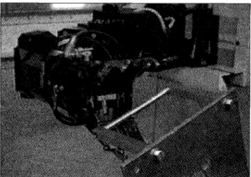
sampling rocks, sediment and fauna beyond diver depth is crude, often relying on grabs, corers and dredgers deployed from surface vessels. Such techniques are not selective, imprecise in sample location, disturb the surrounding envi- ronment during the sample, and usually result in over or under sampling. The use of Unmanned Underwater Vehicles (UWs) (Figure 1) presents the possibility of a cost effective solution to these problems. However, the manipulative abili- ties of such vehicles are currently primitive, using manipula- tors with no dexterity or tactile feedback in their end effectors (Figure 2).The MADEUS project focuses on improving the dexterity and sensory abilities of underwater systems for grasping and manipulation of delicate and other objects. The practical needs of scientists in the ocean are driving technological developments in hand and tactile sensor design, position and contact control systems, and supervisory control of grasping for operation in poor visibility. In Phase I of the project (com- pleted in May 1996), a prototype dexterous three-fingered underwater dexterous gripper (Figure 6) was developed, incorporating force and slip sensors. Techniques for sliding mode control of finger vibration, task function control of fin- ger position/contact, and finger coordination have been 34 IEEE Robotics &Automation Magazine 1070-9932/97/$10.0001997 IEEE December 1997
Figure 1: Unmanned Underwater Vehicle. Heriot- Watt ANGUS 002
demonstrated, to allow grasping of objects up to 150” diameter and 5Kg mass. A “blind grasping” mode of supervi- sory operation has also been developed, using a reactive world modeling and task planning architecture, utilizing only finger contact sensing. The initial prototype operates successfully in the laboratory tank.
Phase I1 (Figure 3) is now under way, to develop two work- cells for wet trials with scientist users. The first will employ a more rugged dexterous gripper design, mounted on an under- water robot arm. The second will develop a two-arm system for coordinated grasping and manipulation of larger or heav- ier objects (Figure 4).
We will summarize some of the achievements of phase I, and the prospects for phase 11, in each of the technology areas. SYSTEM ARCHITECTURE
To integrate the various technological developments, a functional system architecture has been employed (Figure 5). This architecture provides both the context for each partner’s activities, and the hierarchy within which hard- ware and software integration takes place.
At the lowest level is the dexter- ous gripper mechanism itself (HWU-MCE) including actuators. Sensory information from the dex- terous gripper (HWU-CEE), is used at several levels in the hierarchy. For control (DIST), force data and estimates of finger position and velocity are used with strategies for high bandwidth vibration con- trol, and control of finger position and force. This low level control is driven from a medium level cou- pled control, coordinating finger movements for grasping and
manipulation. This in turn is dri- ven by grasp planning (HWU- CEE), which models the observable
Figure 2: Crude Gripper of Typical Underwater Manipulator
tain stable grasps (tele-assistance, supervisory control). Finally, the human computer interface
(IAN)
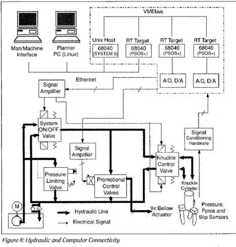
provides a graphical user interface to observe and control the dexterous gripper in both tele-operation and tele-assistance modes. Control, planning and HCI are linked bi-directionally, to allow observable failures in execution to propagate upwards for corrective action.The architecture is implemented on a mixture of HP and PC UNIX workstations and a multiprocessor VME 68040 system under the VMEexec real-time operating system (Figure 8). All processors are interconnected through ethernet using UNIX sockets, in addition to the VME bus connection for real-time boards. Within the project, software interfaces between each partner’s functional modules were defined, and semi-rigorously enforced, to ease the final integration task. Of particular impor- tance was the use of the MATLAFVSIMULINK real-time exten- sions, to allow rapid prototyping of low and medium level control system design in the transition from simulation studies to the real robot. Only a very limited number of additional hand written C-code drivers for handling inter-board communica- tions and VO were required, as well as a few specific routines to
model the finger deflections and Jacobians.
geometry and physical properties
of a grasped object, and reactively AMADEUS Phase 111996-1999
plans actions to obtain and main- Figure SAMMEUS Project Structure
MECHANICAL DESIGN gripper incorporates knuckle joints. These joints are driven in
A fundamental innovation in t h e project has been t h e concert from a small single central hydraulic cylinder via a mechanical design of the dexterous gripper mechanism. simple linkage, and provides each finger with 40" of angular Existing dexterous hands for use in air generally use articulat- rotation. This knuckle movement is sufficient to enable the ed joints, with tendon and pulley mechanisms for actuation. finger tips to touch and grasp small objects (diameter (0)
They are not well suited for use in the ocean, through per- 10") or move apart ceived difficulties with seals, corrosion, ingress of grit and so thatlarger objects water, and hence reliability. The MADEUS system, however, (up to 63150") may utilizes an "elephant's trunk" finger design [ 11, which has be considered largely no moving parts, is naturally pressure compensated A small hydraulic for use at depth, and has passive compliance for robustness. cylinder (O.D. 22mm), The dexterous gripper consists of three modular sections; with both ports at the body, finger, and fingertip (Figure 6), with hydraulic and con- closed end, is used to trol systems as separate units. The modular approach allows a drive t h e machined range of components, materials and geometries to be evaluat- aluminum knuckle ed in the laboratory without extensive reworking of the entire mechanism. Concen- dexterous gripper system, and follows sound underwater tric guide bearing
design principles. cylinders located
a b o u t t h e body of
Finger Design the hydraulic cylinder
minimize any side loads and reduce the risk of the mechanism jamming. Extension
of the piston causes Workcell
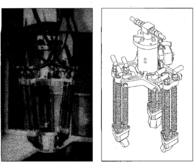
The operation of elephant's trunk fingers relies on the elastic deformation of cylindrical metal bellows with thin convoluted walls. The convolutions ensure that the assembly is signifi- cantly stiffer radially than longitudinally, and that longitudinal extension is therefore much greater than radial expansion when subjected to internal pressure. Currently,
phosphor bronze bellows (14.3" outside diam- eter (OD) and length 125") with 52 active con- volutions and 0.28mm wall thickness are used.
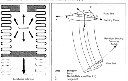
Each finger is made up from three bellows placed in a parallel arrangement forming the ver- tices of an equilateral triangle (pitch center diameter (PCD) 30"). The proximal end of the triad is attached to the knuckle joint of the dex- terous gripper body, the other to an end-plate, which connects each bellow to the other two members of a particular finger. Utilizing a differ- ent pressure in each bellow creates a range of extension forces causing the finger to bend according to the constraints provided by the end plate (Figure 7). The larger the differential pres- sure, the larger the resulting fingertip deflection. In addition to bending, the triangular arrange- ment enables the direction of fingertip move- ment to be controlled.
There is a minimum radius of curvature which can be produced by a finger. This radius is due to the wall thickness, convolution pitch, and the material used in the bellow actuators. The larger the maximum deflection required at the finger tip, the longer the normal length of the actuator must be. A series of plastic belts cov- ered by neoprene slewing supports the actuators along their length, reducing the risk of contact damage or buckling.
Palm Body
To allow the dexterous gripper to grasp a wide
1
range of object sizes, the palm of the dexterous Figure 5:AMADEUSFunctional System Architecture
36 9 IEEE Robotics &Automation Magazine
Figure 6. MADEUS Phase IPrototype Dextrous gripper
Overall height (including fingers): 365 mm Peak finger tip force (straight): 15.45 N
Mass (of gripper):
Knuckle movement +Zoo (minimum): 9 1 0 mm
3.5 kg Target object dimensions:
SENSOR DESIGN AND SIGNAL PROCESSING Grasping and manipulation of delicate objects requires reliable sensing in the finger tips. As a minimum this should measure the magnitude of any applied force, but should further include direction for more complex manipulations. Measurement of slipping may also be of benefit in reactively maintaining a grasp in the presence of disturbances. As with the hand design, simplicity, robustness and tolerance to changing pressure and tem- perature are essential for use in the ocean.
Contact force and slip sensors are currently included within each fingertip of the dexterous gripper design (Figure 9), encapsulated within a compliant silicon rub- ber compound, using a two-stage injection molding process. The force sensor uses strain gauges mounted on a skeleton at appropriate angles. Slip sensing relies on voltage variations in a piezoelectric material (PVDF) as slipping causes vibration at its surface.
A small fifty way push fit connector has been developed to split sensor feedback at the finger tip interface, allowing rapid substitution of t h e finger til, unit as required. A machined housing protects this connector and provides the basic form for the remainder of the finger tip. Water ingress into the Finger deflection (maximum):
Maximum frequency response:
20" (maximum): 5.5 Hz
, 0 1 5 0 ~ ~ housing is prevented by a nitrile O-ring seal. Currently, no sensor is incorporated to mea- been identified). For closed loop position control, therefore, a calibrated model of the finger motion is used, driven by pres- sures measured from sensors within each tube.
the dexterous gripper to flex by movement of a sliding rotary joint on each of the knuckle manifolds. Another rota- tional joint on each knuckle manifold is attached to the sta- tionary o u t e r bearing cylinder of t h e mechanism. Polyamide resin plain bearings and slide rings minimize the friction between all moving surfaces. The angle of the knuckle joint is measured by a rotary potentiometer driven from the knuckle mechanism via a rack and pinion. The potentiometer and drive assembly is housed in a robust oil filled casing, with quad and O-ring seals to prevent water ingress or oil leakage.
The knuckle joint alters the dexterous gripper configura- tion prior to object contact, while the individual finger motions are reserved for grasping and fine manipulation. Large changes in position or orientation of grasped objects must be performed by the arm or wrist onto which the dexter- ous gripper is mounted.
Hydraulic System
The hydraulic system (Figure 8) uses a fixed displacement gear pump with pressure reducing pilot valve to maintain a system pressure of 30 bar. The pressure in each bellow actua- tor is controlled using a solenoid operated proportional con- trol valve with spring return, which has a sigmoid shape static response, with some hysteresis. Due to valve leakage, the min- gers are usually operated above 12 bar to ensure that operation is within the central linear portion.
The control valve for the knuckle joint is a solenoid operated three position direction control valve with spring center align- ment. This enables the flow to the knuckle joint to be either extended, retracted or switched off.
imum pressuve which can be delivered is 7.5 bar and the fin-
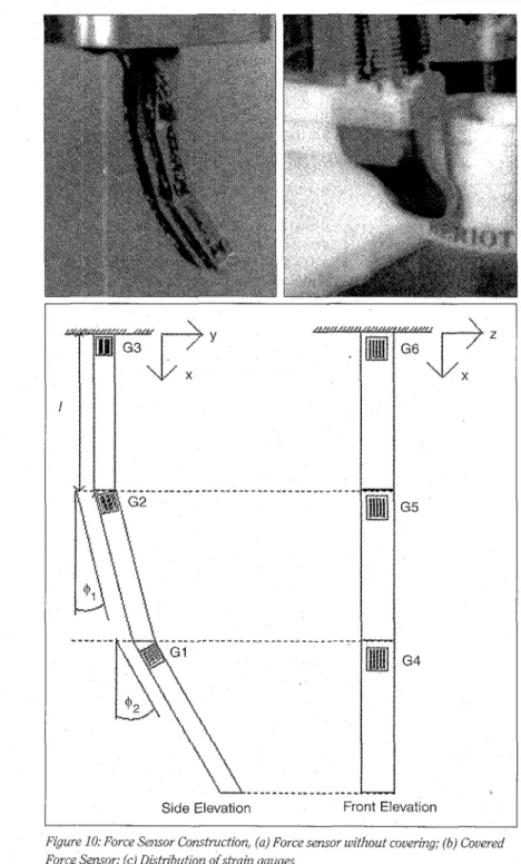
Force Sensor Design
An aluminum skeleton approximating the final shape of the fingertip was constructed, (Figure l o ) , around which the compliant material is mounted. When stress is applied to the finger the structure deforms, and these deformations are measured using an array of 12 strain gauges strategically mounted on the skeletal structure. From these deformations it is possible to deduce the force on the fingertip. The choice of covering is important; if the material is too stiff, there will be a loss in spatial resolution, whereas if it is too compliant transmission of the forces to the strain gauged elements will be poor. Currently, the best candidate material for the cover- ing is a silicone elastomer.
Two quite different methods for determining the forces at the fingertip from the raw strain gauge readings were devel- oped. One uses the finite element approach and the theory of structural stiffnesses, and the other a less mathematically rig- orous but potentially more accurate approach using a fixed gain Kalman filter. These methods, including an analysis of the sensor performance may be found in [3] and [5].
Slip Sensor
Embedded l m m below the surface of the compliant covering of the sensor is a thin (52pm) layer of piezoelectric film
(PVDF) (Figure 11). Piezoelectric film has the property that a charge is developed at its surface when subject to a deforma- tion. This is a dynamic property in that once it stops deform- ing, the charge built up on the surface quickly decays to zero.
It is thus ideal for the measurement of transient phenomena but, on its own, unsuitable for measuring steady state proper- ties. Since the film develops a (transient) charge at its surface when deformed, with suitable signal processing it has the ability to act as a vibration pickup.
When used as a slip sensor, the relative motion between two surfaces causes mechanical vibration in a direction normal to t h e plane of motion. The PVDF produces a charge related to these vibrations, and hence can indicate when a grasped object is slipping. Furthermore, the nature of the signal detected depends on the properties of the grasped object, the grasp force, the speed at which slip is
distribution, which have remarkable geometric properties. The first subset is responsible for the motion of the manip- ulated object, and can be expressed exclusively in terms of “tangential motion forces.” This means that the net resultant wrench applied to the object is due to the superposition of forces directed along the tangent plane at each contact point. The second subset has the role of ensuring the feasibility and the robustness of the grasp, with respect to model uncertain- ties related with friction coefficients, contact distribution and so on. These forces, which typically span a subset of the so called “internal forces” space, are basically formed by the nor- mal forces acting in correspondence with each contact point, taking place and whether the motion is rotational or trans- but not causing any motion, [6].
lational. Analysis of both the time and frequency domain signals s h o u l d t h u s provide f u r t h e r information about the state of a grasp and any slippage, with a possible goal being t h e direct control of slippage during dexter- ous manipulation of an object. LOW AND MEDIUM LEVEL CONTROL SYSTEM DESEN
Since the fingers have natural pas- sive compliance, some grasping and manipulation tasks can readily be achieved open loop. However, to provide more precision in posi- tioning and applied contact force (for delicate o b j e c t s ) , t h r e e areas of closed loop control have
Pressure PI ...._-._.._._____..-..._____ ( _ _ _ _ Longitudinal Extension z 2 Fixed End Resultant Bending Pressures Axis Direction
Y Radial (Reference Direction) z Tangential
Figure 7: (a) Intemal Pressure Causes Mainly Longitudinal Extension; (b) Bending of Flexible Actuator Caused By Internal Pressure Diffwential
been studied:
Low level Of position and
contact force
* Medium level coordinated control of fingers for grasping. Experimental high bandwidth actuation, sensing and con-
trol of finger position.
Low Level Force and Position Control
The low level control module is responsible for positioning the finger during grasping and manipulation, under the direc- tion of the medium level controller. Control of contact forces similarly takes place here, Positioning the finger during grasping is made difficult since there is currently no position sensor on each finger, and hence estimates of finger location must be used, based on bellow pressures and calibrated mod- els of finger motion. Positioning the finger during manipula- tion uses the force sensors described in the previous section on sensor design and signal processing.
The first problem was to devise a model for representing, in a form suitable for both planning and control, the whole set of interaction forces acting on the surface of a manipulated object during generic manipulation operations. To this end, a suitable and original decomposition has been made, capable of repre- senting any set of contact forces. In particular, it has been found that there exist two subspaces generated by the contact forces
One advantage offered by this kind of decomposition has been a clear geometrical insight into the structure of the space of the contact forces during manipulation operations, and the decoupling of forces responsible for object motion and the grasp robustness. On the basis of these results, closed loop robot control algorithms, including iterative learning techniques (very effective in cases of completely unknown robot dynamics), have been designed allowing proper control of object motion and internal forces under the assumption of proper position and contact forces feedback 171. Stability and robustness properties of the proposed control schemes, with respect to possibly unknown robots dynamics were also assessed. Simulation results also confirmed the effectiveness of the proposed approach.
The second significant outcome of this phase of the research program, has been the definition of the general framework for the design of the control architecture for the
AMADEUS dexterous gripper. In particular it has been neces-
sary to devise a control formulation which could take into account the peculiarity of the mechanical design of the dex- terous gripper (the elephant’s trunk design), and on the other hand allow a “standard” formulation of significant classes of robotic tasks.
l4zGA
I
ManIMachine InterfaceiGE23
I
Planner PC (Linux) , J i I I: Ethernet AmDlifier I /Figure 8: Hydraulic and Computer Connectivity
slip 1 Sensor Hydraulic Bellows Assembly Finger End Plate Connector Assembly Finger Tip Assembly
Figuve 9: Detachable fingev tip, with fovce and slip sensoys, (a) Fovre sensoY skeleton on Fingertip; (b) Fingertip schematic
tion and task control, adopting a hierarchical control design. This kind of architecture in turn can be easily implemented onto multi- processor hardware architectures, and easily expanded if more functionalities are needed, mostly due to its natural modularity.
Medium Level Coordinated Finger Control Medium level control is responsible for directing the low level actions of fingers, to control the grasp and subsequent manipula- tion of an object, under instruction from the grasp planner (which we will describe in our discussion of supervisory control of grasping and manipulative behaviors in the next section) with supervisory control, or the human computer interface (see the fol- lowing section on man-machine interface design) with teleoperation. At the medium level, the robot system can be seen as a purely velocity controlled kinematic struc- ture. In particular the control signals, which are generalized velocity demands, are computed in real-time on the basis of a suit- able feedback matrix defined using a Lya- punov design procedure for the specific robotic task in hand.
Previously, very simple (typically pro- portional) velocity control loops have been used at the low level, for real-time tracking of the velocity reference signals supplied by the medium level control modules. This control paradigm has been extensively and successfully tested by simulations and actual experiments, using “conventional” rigid industrial robots. However, t h e
AMADEUS dexterous gripper features unique mechanical characteristics (e.g., very large elastic deformations) due to the actuation principle adopted. These had to be carefully investigated, to ensure the success of the proposed control architec- ture for this specific case.
In particular two key elements are need- ed to implement even a very simple position control scheme using the “Task Function” approach. The first one is, of course, the availability of measured or estimated feed- back data giving the positiodorientation of the mechanism to be moved. The second item, less critical in terms of accuracy, is the Jacobian transformation from task coordi- nates to the robot’s generalized coordinates. In the case of the fingers of the AMADEUS The philosophical approach adopted has been the so called
“Task Function” formulation, formerly introduced by Espiau, Samson, and La Borgne. The basic idea on which this control formulation is founded, is that of separating the level of actua-
dexterous gripper, these have been critical issues, as no posi- tion sensors were available at the time when the control sys- tem was designed, and on the other hand it was not clear how to describe the deflections of each finger using only a finite
(and possibly limited) number of generalized coordinates. To overcome these problems it was initially decided to develop a theoretical framework as well as software tools, for an accurate modeling and analysis of the mechanics of deformable structures, equivalent to those designed for build- ing the fingers of the AMADEUS dexterous gripper. Subse-
quently, simplified deflection models have been designed and validated to allow for real-time implementation of the designed control schemes.
The most challenging aspect of this task was represented by the need to model the non-linear dynamics of large spatial
elastic deformations, which were predicted to be a feature of the dexterous gripper under design,
[lo].
Despite the ele- gance of the theory developed, the models which have been obtained were too complex to be implemented in real-time applications.However, experimental evidence showed that the actual dynamic behavior of the hydraulically actuated fingers, subject to pressures varying up to frequencies of lOHz, was well damped and smooth. This dramatic simplification suggested the idea of using a standard kinematic chain formed by a sequence of prismatic and spherical joints coupled with linear
Z
G5
G4
Side Elevation Front Elevation
Figure 10: Force Sensor Construction, (a) Force sensor without covering; (b) Covered Force Sensor; (c) Distribution of strain gauges
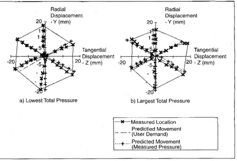
and rotoidal springs to model the deflections of each finger when subject to control pressures and/or external forces and torques possibly due to contact of the finger with the environment. The basic result of this idea has been that of designing a recursive pro- cedure which allows estimation of the “static” deflec- tion of each finger corresponding to specific control pressures (available in real-time from the pressure transducers installed in the fingers) and contact force/torque measurements (available through the sensors mounted on each fingertip).
Software modules have been designed to validate this simplified, but reasonable, modeling technique, and the experimental evidence obtained by compar- ing the working envelopes obtained from actual experimental data and those produced by the simu- lator showed an excellent similarity (Figure 12).
High Bandwidth Finger Actuation Sensing and Control
To damp vibration modes of the flexible finger requires a higher bandwidth actuator than the hydraulic proportional valves used in the prototype dexterous gripper. An ancillaw study has therefore been carried out to develop a higher bandwidth electrohydraulic actuator and associated position sensing and closed loop control method. The actua- tor system comprises a linear motor, a position sen- sor and a set of control bellows (Figure 13).
For each tube, two voice-coil motors are used,
similar to those used in high fidelity speaker design to move woofer and sub-woofer units at audio fre- quencies. These actuate a low volume hydraulic sys- tem comprising a pair of bellows connected by a flexible tube. The system is filled with oil at very low
pressure, thus assisting a fast propagation of move- ments from one bellow to another without energy and bandwidth dissipation through friction effects. If amplification or reduction ratios are needed, bellows can be of different sizes. The position sensor used is simply a proximity sensor measuring the control bel- low length. From knowledge of this value we can sub- sequently obtain the fingertip position in its workspace, by means of simplified models.
For control, the problem is one of a second order non linear uncertain system using only estimates of position. Previously, a sliding mode approach to counteract system uncertainties and disturbances
Figure 11: PVDF Slip Sensor, (a) prior to potting; (b) typical data with and
has been effective in controlling a simplified model of the fin- ger [11]. Building on this, a new algorithm exploiting the robustness properties of the classical time-optimal bang-bang control has been designed and tested. The results are highly satisfactory even in comparison with traditional P.I.D. con- trollers which, require lengthy calibration procedures. Figure 14 shows a plot of the tracking behavior of the system with respect to a 6 Hz sinusoidal signal.
To realize a complete three-fingered dexterous gripper using this approach, nine such devices would be involved. While this may initially seem very cumbersome, suitable miniaturization of the actuator can be carried out when the force/displacement specifications for the second prototype
MADEUS dexterous gripper are defined. A further contraction of the size could be accomplished if the magnetic circuits for all the nine motors were compacted in three or even one sin- gle block, and an efficient cooling system suitably designed. Such miniaturization of the actuation system is being consid- ered further in current investigations.
SUPERVISORY CONTROL OF GRASPING AND
MANIPULATION BEHAVIORS To enable grasping and manipulation in con- ditions of poor visibility, or when the gripper is obscured from the user’s field of view, we are experimenting with a form of supervisory control we call “blind grasping,” In the cur- rent implementation, the user tele-operates the gripper to the vicinity of the object. On instruction, the system uses available sensors (currently finger force and position esti- mates) to model the geometric, mass and friction properties of the object, and instructs the medium level control with necessary information to carry out a grasp. Failure pro- vides additional information about object attributes to assist in future attempts. Since the AMADEUS dexterous gripper is not
anthropomorphic, in principle this mode of operation can utilize a wider range of finger
2ooo ~
1500
i
3 500
-500
t
Graph of Slip Signal V Time Samples Taken at 1 kHz
0 10 20 30 40 50 60 70
thout slipping
motions than tele-operation through a data glove.
Three required properties of our reactive task planner are: 1. To be able to receive and process sensory data so that meaningful observations can be made, and to generate an internal model of the world based on the data.
2. To be able to make observations on and draw conclusions about the state of the world, based on the sensory data received and the internal model of the world.
3. To be able to form plans of action to alter the sensed world to achieve specified goals passed down from the user.
The grasp planner uses a planning and world modeling architecture previously developed for tele-assistance with sub- sea robots [ 121. We have split the planner into three modules, one for each of the required properties above. These modules are the World Model, the ConcepUPercept network, and the Task Sequence Network (Figure 15).
The World Model is a passive store of the geometric state of the world as input a priori and subsequently sensed. It is then refined into a ConceptlPercept network which semanti-
cally defines the context and attributes of each object. Since
Radial Radial
Displacement Displacement
Tangential Tangential
Displacement Displacement
- Z ( m m ) - - 2 (mm)
a) Lowest Total Pressure b) Largest Total Pressure
+Measured Location Predictied Movement (User Demand) ---.,.--.Predicted Movement
_ _
Figure 12: Working envelope of the MADEUS fingers
the environment is unstructured, it does not attempt to pre- dict future states of the world, or model the behavior of other objects (e.g., effects of external forces such as gravity). Our philosophy is to mix planning and execution, thus using the World itself as the means of exploring “possible futures.”
Concepts are atomic notions that can be used to describe
the world in a semantic way. They represent object attributes such as “redness,” “heaviness,” “largeness,” [‘compliance,” etc. In general, instances of these concepts (percepts) will rely on data input from several sensors. Thus, there is a distinction between the physical system sensors and the virtual sensors that the concepts represent. Sensory concepts exist at the fringes of the network, and provide the link between the net- work and the real world. Internal concepts come from the combination of any number of other concepts. These are thus non-atomic notions providing a richer description of an object (e.g., small and compliant).
To generate actions based on the state of the world, a store of pre-defined action sequences is used, called the Task Sequence Network. These actions may be atomic (i.e., indivis- ible commands) or may represent a more sophisticated set of activities, each one an action sequence in its own right. There is therefore an innate hierarchical ordering in the sequencing of action. Actions and action sequences have world model concepts as pre-conditions which, when met, indicate the action has been successfully achieved. Atomic actions invoked from the network are passed via the medium and low level control to the robot.
Task requests from the operator cause a goal demand (e.g., hold object in gripper) to be passed to the Task Sequence Net- work. The state of the World Model (so-called referential knowledge) along with the goal, act as preconditions to lists of actions (so called episodic data) which make up the Task Sequence Network. From the potentially suitable set of task sequences, whose preconditions are satisfied, the most strongly favored is executed.
Execution of atomic actions via the medium level control and the robot causes changes in the environment which are then sensed by available sensors, and interpreted to update the structure and beliefs in the World Model. This in turn changes the preconditions to the Task Sequence Network. If the goal’s preconditions are initially satisfied, the goal has been achieved and the task terminates. If the preconditions are not satisfied, an action sequence is invoked to change the state of the world so that preconditions are satisfied. Succes-
sive activation of action
sequences thus changesthe
stateof
the world so that all goal preconditions are met, and the goal is achieved. In this way, the Planner is error driven, causing changes in the world according to exceptions. There is there- fore no off line a priori planning, as planning and execution are interleaved. The World itself acts as the means to explore on line the best route to success, and reactivity comes in the way action sequences are triggered according to the state of the world. Task complexity and predictability in behavior is managed as a natural byproduct of the hierarchical nature of action sequences
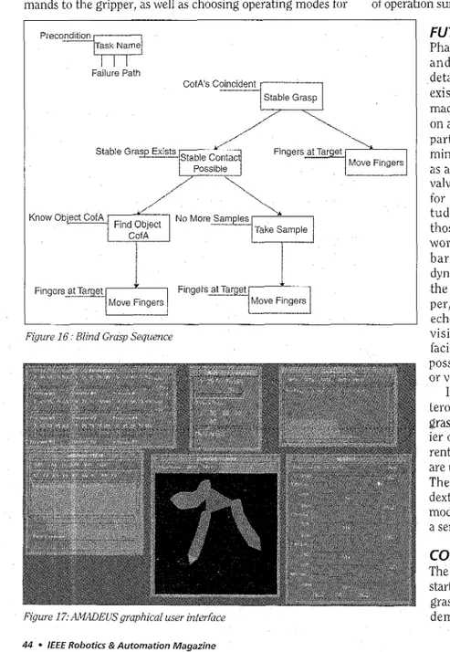
By way of example, Figure 1 6 shows part of the task sequence network for blind grasping. The task planner attempts to discover the shape of the object by making suc-
cessive law force contacts at various points around the object’s perimeter. Once sufficient data has been obtained, the object‘s center of area is calculated in the world model. From this, finger contact points are calculated, such that the grasp center is coincident with the object center of area. This gives a good first attempt at a stable grasp configuration, assuming the object’s centers of area and mass are approxi- mately coincident.
MAN MACHINE INTERFACE DESIGN
Currently, MADEUS uses a graphical user interface primari-
ly designed to allow laboratory testing of the dexterous grip-
Figure 13: Actuators and sensors for high bandwidth control, (a) Trio of electrohydraulic actuators; (b) Tesf finger design; (c) Position Sensor
3 ‘ 1 0 0.33 0.66 1 time 5 - 0 - 5 1 0 0.33 0.66 1 time 0 0.33 0.66 1 time 10
L
A
3 1.5 0 1.5 3 phase planeFigure 14: Tracking Behavior ofFinger With High Bandwidth Electrohydraulic Actuation The Operator
c
Task Request
Rerentfa/ Knowledge Epaodfc Data
Sequence __I
---
r. Choose Suitable Sensory Interpretation The Environment Task SequenceFigure 15: Task Planning Architecture
per and its subsystems by engineers (Figure 17). The man machine interface (MMI) operates by exchanging messages with the high level control modules (Grasp Planner and Medi-
um Level Control) via a Local Area Network.
To achieve this goal, a particular structure has been adopted which is composed of a seferies of diffeferent modules, and consists of a nucleus and several independent processes. The nucleus contains all functions for the management of work sessions, data storage and general graphic interface functions. The independent processes are related to specific activities and each refers to a particular window. The main MMI modules are the “Boss,” “Slider,” “Keeper,” and
“Recorder.” The Application Processes are a
series of concurrent processes which are regulated and managed by higher-level MMI modules. They will be examined in detail below. A Common Memory Area (MECON) has been considered necessary to store all data that can be used by more than one module, as well as processes and all messages which can be exchanged with the “actuation” parts of the gripper. All communications between modules are pro- vided via a series of queues, and conflicts between concurrent processes are managed by appropriate regulation mechanisms (semaphores).
The main functions and usage of each MMI module may be summarized as follows:
Boss: The main initialization system, to control the system’s global initialization pro- cedures: manages the input devices (mouse, keyboard, 9-knob board), and displays sys- tem messages;
Slider: Runs independent processes and manages conflicts;
Keeper: Manages the Common memory area to grant communications between mod- ules and with control levels;
Recorder: Saves on disk all significant data and commands processed by the MMI.
The Application Processes have direct responsibility for managing data, controlling workflows and displaying necessary informa- tion. Their features and usage may be sum- marized as follows:
Session: The MMI session control process to set all session parameters;
3Dgraph: The 3D graphical representa- tion process, to create a synthetic image of the gripper on the basis of its geometrical model and of status information;
Press: The pressure control process to manually control the pressure of gripper palm and fingers;
Finger: The finger control process to manually set t h e geometric position of the fingers:
Grip: The gripper control process, to enable the user to manage the high-level and automatic oper- ations of grasping, releasing and manipulating objects;
Monitor: The data monitoring process, to display the sta- tus of selected variables and parameters.
For the “Press,” ‘(Finger,” and “Grip,” processes, three dif- ferent ways of entering data and commands are used:
a) utilization of keyboard, mouse and a combination of dialog boxes;
b) conversion of the movement of each knob into a series of commands;
c) reading of sequential files.
Several kinds of data and commands are exchanged
between the MMI and other control modules via the
LAN,
and packets are sent and received asynchronously. Data include hydraulic system values, the geometric values of gripper shape and positioning, forces, torques and slip measurement values. Commands include pressures in each tubes, length, bend and spin of each finger, orders to grasp, manipulate and release objects, and status commands. All data for internal operations are exchanged via the MECON.With reference to Figure 17, the main menu in the ‘Boss’ window allows the user to choose from various options: the
Press, Grip, or Bend application, the Sdgraph process, and the
Monitor process. In the Painter window the gripper is shown
in the position described by data coming from the HLC: three fingers and the palm are shown, each represented by a differ- ent color. The user can change the visual perspective simply by moving the mouse cursor inside the window. In the Press
window it is possible to set knob functions and send com- mands to the gripper, as well as choosing operating modes for
command handling. Knobs can be linked to any inputted quantity and their values are shown through a series of bars. The other two windows, Bend and Grip, are used in a similar way to the Press window, following the same principles. The so-called Oscilloscope Emulator monitors chosen variables: four different tracks are shown, each tracing the values of a given variable by means of a graph; the name of the represent- ed variable is on the left of each trace, together with the lower and upper limits of the represented values. The represented variable may be changed, as may the horizontal resolution and vertical limits. The values shown may be “frozen” to allow easier examination by the user.
The MMI has been used successfully in system trials, and was able to display small hunting behaviors of the fingers dur- ing control system tuning, that were easier to see than on the real gripper. For the future, additional work is required to adapt the modular design and incorporate facilities and modes of operation suited to the operational needs of scientists.
Failure Path
CofAs Coincident
i-1
Stable Grasp
ow Object CofA
Take Sample
Figure 16: Blind Grasp Sequence
Figure 17: AMADEUS graphical user interface
44 0 IEEE Robotics &Automation Magazine
FUTURE ACTIVITIES
Phase I1 of the programme has now commenced, and t h e group a r e currently defining more detailed scientific requirements and trials. The existing dexterous gripper technology is being made more rugged, reduced in size, and mounted on an existing seven-function underwater arm. Of particular importance will be developments in miniaturization of the electrohydraulic actuators, as a possible substitute for hydraulic proportional valves. We are also further researching materials for bellows construction, to obtain better longi- tudinal and lateral stiffness properties than those of phosphor bronze. We hope to be able to work with hydraulic pressures higher than 30
bar, to obtain larger motions with a better dynamic range. In pdrdllel, an investigation into the incorporation of vision sensors in the grip- per, using CCD cameras, fiberoptic bundles or echo sounders is about to commence. Computer vision has been highlighted as an important facility for these applications, and may open up
possibilities for related research in recognition or visual seuvoing.
In addition to further development of the dex- terous gripper, the project is also progressing to grasping and manipulating much larger and heav- ier objects using a pair of UW manipulators. Cur- I rently, two of these special-purpose manipulators are under construction for mounting on a toolskid. The computational hierarchy developed for the dexterous gripper will be replicated, with minor modification, and applied to this new workcell, and a series of experiments are being planned.
CONCLUSIONS
The AMADEUS programme has made a promising start in improving our ability to carry out remote grasping and manipulation in the ocean. We have demonstrated each of the technological areas
described in this paper working together in practice in the laboratory as part of the programme first phase.
Although the project is currently focused on a set of marine science tasks, there are numerous other environ- ments where the technology can be applied. From an indus- trial viewpoint, AMADEUS could assist with other remote complex operations, where cost savings are required or haz- ard levels are high. Examples are in the offshore, nuclear and manufacturing industries, for cleaning, welding, dismantling or maintenance.
By working closely with scientist users in the second phase, we are well placed to produce systems that practically address the needs of users, and have the possibility of future exploitation to the benefit of European industry.
REFERENCES
Project deliverables providing more detailed reports on the system specification and the technological developments are available from the authors. The following are a selection from published articles on the subject. Further information on the project can be found at http:llwww.cee.hw.ac.uklsubsealhwl
index. html
[l] Davies, J.B.C., Robinson, G. A Flexible Dexterous Gripper, Proc. SPIE Int. Conf: Robotics Research, Cambridge, Mass. Septem- ber 1995.
(21 Lane, D.M., Davies, J.B.C., Sneddon, J., O’Brien, D.J., Robinson, G.C. Aspects of the Design and Development of a Subsea Dextrous Grasp- ing System, Proc. IEEE OCEANS 94, Brest, France, Sept 13-16 1994 Vol I1 pp. 174-181.
[3] Lane, D.M., Davies, J.B.C., Robinson, G., O’Brien, D.J., Sneddon, J., Seaton, E., Elfstrom, A. The AMADEUS Dextrous Subsea Hand-Design, Modelling and Sensor Processing, International Advanced Robotics Programme (IARP) Workshop on Subsea Robotics, Toulon, France, 26-29 March 1996. Submitted IEEE Journal Oceanic Engineering, July 1996.
[4] Bartolini, G., Casalino, G., Ferrara, A., Cannata, G., Veruggio, G., Lane, D.M., Sneddon, J., O’Brien, D.J., Davies, J.B.C., Robinson, G. AMADEUS: Advanced Manipulator for Deep Underwater Sys- tems, 2nd MAST Days and Euromur Market, Sorrento, Italy, November 1995.
[5] O’Brien, D.J., Lane, D.M. The Design, Modelling and Analysis of a Strain Gauge-based Force Sensor For Subsea Applications Using the Structural Stiffness Method. 7th International Con- ference on Advanced Robotics (ICAR ‘95) Sant Feliu de Guixols,
Spain. September 20-22, 1995.
[6] Aicardi, M., Cannata, G., Casalino, G. Contact Force Canonical Decomposition and the Role of Internal Forces in Robust Grasp Planning Problems, Int. Journal o f Robotic Research, MIT Press, June 1996 (to appear, August 1996).
[7] Aicardi, M., Caiti, A., Cannata, G., Casalino, G. Stability and Robust- ness Analysis of a Two Layered Hierarchical Architecture for Closed Loop Control of Robots in the Operational Space, IEEE Int. Conf: on Robotics andhtomation, Nagoya, Japan, 1995.
Control Architecture for the Control of Underwater Robots, IFAC
workshop on Control Applications for Maritime System, CAMS ‘95,
Throndheim, Norway, 1995.
191 Casalino, G., Aicardi, M., Cannata, G. Detaching Phenomena in the Learning Control of Manipulation of Rigid Objects, IFAC Symp. on Robot Control (SVROCO) ‘94, Capri, Italy, 1994.
Bartolini, G., Cannata, G . , Casalino, G., Ferrara, A. A Hierarchical
[ l o ] Pagano, P. A Mathematical Theory for Finite Deformations Within Multiarticulated Elastic Structures, Ph. D. Thesis on Electronic Engineering, DIST-University of Genova, Italy, 1995 (in Italian). [ll] Bartolini, G., Ferrara, A., Usai, E. Application of a sub optimal dis-
continuous control algorithm for uncertain second order systems,
Int. Joumal ofRobust and Non Linear Systems (to appear). I121 Lane, D.M., Knightbridge, P.J. Task Planning and World Modelling
For Supervisory Control of Robots in Unstructured Environments,
IEEE Int. Conf Robotics undilutomation, Nagoya, Japan May 21-27 1995 pp. 1880-1885.
[ 131 Lane, D.M. The AMADEUS Dextrous Underwater Grasping System, International Journal of Systems Science, Vol. 29, No. 4, April 1998. [ 141 Robinson, G., Davies, J.B.C., Seaton, E., Mechanical Design, Opera-
tion and Direction Prediction of the AMADEUS Gripper, Internation- al Journal of Systems Science, Vol. 29, No. 4, April 1998.
[15] O’Brien, D.J., Lane, D.M., Force and Explicit Slip Sensing for the AMADEUS Underwater Gripper, International Journal of Systems Science, Vol. 29. No. 4, April 1998.
[16] Angeletti, D., Cannata, G., Casalino, G., The Control Architecture of the AMADEUS Gripper, International Journal of Systems Science, Vol. 29, No. 4, April 1998.
171 Bartolini, G., Coccoli, M., Ferrara, A., Vibration Damping and Second Order Sliding Modes in the Control of a Single, Finger of the AMADEUS Gripper, International Journal of Systems Science, Vol. 29, No. 4, April 1998.
181 Lane, D.M., Pickett, M., Task Planning for Dextrous Manipulation Using Blind Grasping Tele-Assistance, International Journal of Sys- tems Science, Vol. 29, No. 4, April 1998.
191 Veruggio, G., Bono, R., Virgili, P., The AMADEUS Man Machine Interface, International Journal of Systems Science, Vol. 29, No. 4, April 1998.
[ZO] Lane, D.M., Davies, J.B.C., Robinson, G., O’Brien, D.J., Pickett, M., The AMADEUS Dextrous Subsea Hand: Design Modelling and Sensor Signal Processing, accepted for publication, IEEE Journal Oceanic Engineering, 1998.
This article on the AMADEUS projects was jointly authored by twenty scientists and engineers from the five participat- ing institutions.
David M. Lane, D.J. O’Brien, and M. Pickett are from the Ocean Systems Laboratory of the Department of Computing and Electrical Engineering (CEE), all at Heriot-Watt University, Edinburgh, Scotland EH14 4AS, [email protected].
J.B.C. Davies, G . Robinson, D. Jones, and E. Scott are from the Department of Mechanical and Chemical Engineer- ing (MCE), also a t Heriot-Watt University, mech- jd@bonaly .heriot-watt.ac.uk.
G. Casalino, G. Bartolini, G. Cannata, A. Ferrara,
D.
Angelleti, and M. Coccoli are with DZST, University of Genoa, Italy, [email protected], [email protected].G. Veruggio, R. Bono, and P. Virgili are with the Robotics Dept., Instituto Automazione Navale (IAN) CNR, Viale Causa, Genoa, Italy
,
[email protected]. mr.it.M. Canals, R. Pallas, and E. Gracia are with the Department of Geology, Geophysics and Paleontology, University of Barcelona (UB), Spain. [email protected]. ub.es.
C. Smith is with the Institute of Marine Biology of Crete
(ZMBC), Heraklion, Crete, Greece, [email protected].