1
Università degli Studi di Ferrara
Dipartimento di Ingegneria
Coordinatore: Chiar.mo Prof. Ing. Stefano Trillo
SHAPE MEMORY ALLOYS AND POLYMERS:
EXPERIMENTAL 1D MECHANICAL
CHARACTERIZATION AND APPLICATIONS
Settore Scientifico Disciplinare ICAR/08
Anni 2011/2013
3
SUMMARY
Recent advances in materials engineering have given rise to a new class of materials known as active materials. These materials when used appropriately can aid in development of smart structural systems. Smart structural systems are adaptive in nature and can be utilized in applications that are subject to time varying loads such as aircraft wings, structures exposed to earthquakes, electrical interconnections, biomedical applications, and many more. Materials such as piezoelectric crystals, electro-rheological fluids, shape memory alloys (SMAs) and shape memory polymers (SMPs) constitute some of the active materials that have the innate ability to response to a load by either changing phase (e.g., liquid to solid), and recovering deformation. Active materials when combined with conventional materials (passive materials) such as polymers, stainless steel, and aluminum, can result in the development of smart structural systems (SSS). SMAs and SMPs have a unique ability to recover extensive amounts of deformation (up to 8% strain for SMAs and up to 300% strain for SMPs). This Dissertation focuses on a subclass of active materials, namely shape-memory materials; in particular the focus is on the experimental assessment of two one dimensional constitutive models for NiTiNOL, the most commonly used commercially available SMA with application to the development of a new seismic protection device for masonry historical constructions which has been conceived and constructed at the University of Ferrara and on the mechanical characterization of a brand new shape memory polyurethane named DESMOPAN, patented by Bayer Material Science. Experimental tests on NiTiNOL were conducted in the laboratories of the University of Ferrara, the shape memory alloy device has been tested in the laboratories of the University of Florence and experimental tests on DESMOPAN were conducted in the laboratories of the RWTH Aachen University. The interest on these materials is driven by their potential applications in the developing of new anti-seismic dissipation devices for masonry historical buildings.
The present dissertation is subdivided into four chapters.
First chapter contains a general discussion on smart materials, with a particular focus on shape memory alloys and shape memory polymers. Of both classes of materials an introduction on their mechanical behavior has been outlined and a broad review of their potential applications both in civil engineering and in other fields (such as the biomedical one) has been presented.
Second chapter deals with the first theme on which the PhD activity was focused on: a comparative assessment of two 1D constitutive models for shape memory alloys wires based on an experimental campaign carried at the University of Ferrara in which two NiTiNOL wires of different composition
4
suitable for seismic applications were tested. The models are representative of two broad classes of constitutive models for shape memory alloys. The goal was to determine which kind of model was best suited to predict experimental observation on real specimens.
Third chapter describes the experimental activity of design, construction and testing of a new seismic dissipater based on the superelastic properties of NiTiNOL wires. The device was subject to 1D traction tests at the University of Ferrara and to quasi-static tests when applied on scale models of masonry buildings at the University of Florence. Finally some numerical simulation was carried on in order to replicate the results obtained during the testing of the device.
Finally, fourth chapter describes the experimental activity that was conducted at the RWTH Aachen University on the mechanical characterization of a new type of shape memory polymer, namely DESMOPAN, produced by Bayer Material Science. 1 dimensional thermo-mechanical tests where carried on polymer bone-shaped specimens in order to assess their thermo-mechanical behavior to set the basis for future research on shape memory polymers constitutive modeling.
5
Summary
SUMMARY ... 3
1. INTRODUCTION TO SMART MATERIALS ... 7
1.1 General discussion ... 7
1.2 Martensite and Shape-Memory Effect ... 10
1.2.1 Introduction ... 10
1.2.2 A microscopic perspective of Martensite ... 10
1.2.3 A macroscopic perspective of Martensite ... 15
1.2.4 The origin of Shape Memory Effect ... 17
1.2.5 Stress-induced Martensite and Superelasticity ... 19
1.2.6 Mathematical background for martensitic transformation ... 21
1.2.7 Phenomenological theory of the martensitic transformation ... 23
1.2.8 Thermodynamic aspects of the martensitic transformation... 24
1.2.9 Overview of applications of shape memory alloys ... 30
1.3 Shape memory polymers ... 52
1.3.1 Introduction to SMP’s ... 52
1.3.2 Thermally Induced Shape-Memory Effect in Polymers ... 54
1.3.3 Application of Shape-Memory Polymers ... 62
2 A COMPARATIVE ASSESSMENT OF TWO CONSTITUTIVE MODELS FOR SUPERELASTIC SHAPE-MEMORY ALLOY WIRES ... 67
2.1 Introduction: state-of-the-art of the modelling approaches of SMA behavior ... 67
2.1.1 Literature review: SMA phenomenological models ... 69
2.1.2 Literature review: microscopic thermodynamic models with dynamic phase transition ... 76
2.1.3 The work of dos Santos and Cismasiu (2010) ... 78
2.2 Motivation ... 79
2.2 Kim and Abeyaratne model (1995) ... 81
2.3 Auricchio, Fugazza and DesRoches model (2008) ... 88
2.4 Numerical schemes adopted ... 91
2.5 Models calibration ... 92
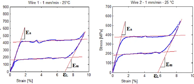
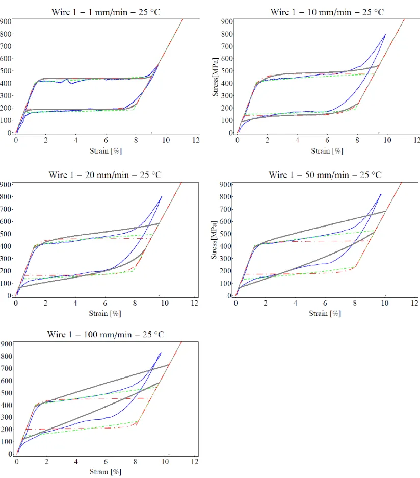
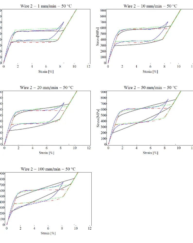
2.5.1 Material characterization of superelastic wires ... 92
2.5.2 Parameters identification ... 94
2.5.3 Further results on parameters identification for the KA model ... 97
2.5.4 Further results on parameters identification for the AFD model ... 99
2.6 Comparison between models ... 100
6
3 FIRST EXPERIMENTAL RESULTS ON AN INNOVATIVE SOLUTION: A SMA-BASED SEISMIC PROTECTION
DEVICE IN SERIES WITH FRP REINFORCEMENT ... 107
3.1 Basic ideas and motivation ... 107
3.2 Possible applications ... 108
3.3 Description of the new proposed SMA multiplateau device and of the CFRP+SMA retrofitting system 111 3.4 Experimental tests and application to a simple scale building masonry model ... 118
3.4.1 Tests without the SMA device ... 118
3.4.2 Tests with the SMA device ... 127
3.5 Some numerical simulation ... 136
4 EXPERIMENTAL INVESTIGATION OF SHAPE MEMORY POLYMER STRIPS: THE CASE OF DESMOPAN DP 2795A. ... 140
4.1 Introduction ... 140
4.2 The material under investigation: DESMOPAN DP 2795A ... 144
4.3 The experimental setup ... 146
4.4 The Tests ... 152
4.5 Concluding remarks ... 163
4.6 Final conclusions ... 164
4.7 Acknowledgements ... 164
7
1. INTRODUCTION TO SMART MATERIALS
1.1 General discussionShape memory materials (SMMs) are featured by the ability to recover their original shape from a significant and seemingly plastic deformation when a particular stimulus is applied (Otsuka and Wayman 1998). This is known as the shape memory effect (SME). Superelasticity (in alloys) or visco-elasticity (in polymers) are also commonly observed under certain conditions. The SME can be utilized in many fields, from aerospace engineering (e.g., in deployable structures and morphing wings) to medical devices (e.g., in stents and filters) (Otsuka and Wayman 1998), (Funakubo 1987), , (Lipscomb and Nokes, The Applications of Shape Memory Alloysin Medicine 1996), (Duerig 1990). This paragraph aims to introduce and summarize the most recent advances in SMMs. The focus is twofold. One is on the new features found in traditional SMMs, namely shape memory alloys (SMAs) and shape memory polymers (SMPs), which are the object of this Dissertation, and the other is on a newly emerging type of SMM, namely shape memory hybrid (SMH). The latter enables non-experts to design the SMMs with tailored properties/features for a particular application.
Despite the fact that the SME had been found in an AuCd alloy as early as 1932, the attraction of this phenomenon was not so apparent until 1971, when significant recoverable strain was observed in a NiTi alloy at the Naval Ordinance Laboratories, USA (Funakubo 1987). Today a wide range of SMAs have been developed in solid, film and even foam shapes. Among them, only three alloy systems, namely NiTi-based, Cu-based (CuAlNi and CuZnAl) and Fe-based, are presently more of a commercial importance. A systematic comparison of NiTi, CuAlNi and CuZnAl SMAs, in terms of various performance indexes, which are of engineering application interest, has been done (W. Wang 2002). NiTi should be the first choice since it has high performance (Otsuka and Ren 2005) and good biocompatibility. The latter is crucial in biomedical applications, for instance stents and guide wires in minimally invasive surgery (Pelton, A. 1997). Cu-based SMAs have the advantages of low material cost and good workability in processing, and some of them even have the rubber-like behavior after aging in a martensite state (Ren and Otsuka 1997). The SME in Fe-based SMAs is traditionally known to be relatively much weaker and Fe-based SMAs were most likely used only as a fastener/clamp for one-time actuation largely due to the extremely low cost (Funakubo 1987), (Pelton, A. 1997). However, Tanaka et al. (Y. Tanaka 2010) recently reported a ferrous polycrystalline SMA showing huge superelasticity (13%) and high tensile strength (over 1 GPa).
8
All these SMAs are thermo-responsive i.e., the stimulus required to trigger the shape recovery is heat. In recent years, good progress has been made in developing ferromagnetic SMAs, which are magneto-responsive (Karaca and et al. 2009). However, thermo-responsive SMA has matured more from the real engineering application point of view and many commercial applications have, so far, been realized (Otsuka and Wayman 1998), (Funakubo 1987), (Duerig 1990).
In addition to the SME, some of the SMAs also have the temperature memory effect (TME), so that the highest temperature(s) in the previous heating process(es) within the transition range can be recorded and precisely revealed in the next heating process (Sun and Huang 2010). Partially different martensite after a thermal programming processis believed to be the underlying mechanism for the TME. Based on the same principle, a piece of SMA strip can be thermo-mechanically programmed to bend forward and then backward upon heating. This is a kind of phenomenon, known as the multi-SME (Xie, Tunable polymer multi-shape memory effect 2010), in which a piece of SMM recovers its original shape in a step-by-step manner through one or a few intermediate shapes. The multi-SME can be utilized to work virtually as a machine, but the fascinating point here is that the material is the machine (Battacharya and James 2005)
.
Let’s now introduce shape memory polymers. From the engineering aspect, tailoring the material properties of polymers is much easier than compared with that of metals/alloys (Xie and Rousseau 2009), (Yakacki 2008). In addition, the cost (both material cost and processing cost) of polymers is traditionally much lower. A variety of SMPs have been invented and well-documented in the literature, while presently new ones keep on emerging every week, if not every day (Mather, Luo and Rousseau 2009), (Liu, Qin and Mather 2007). In addition to the above-mentioned advantages, SMPs are much lighter, have much higher (an order higher at least) recoverable strain than SMAs, and can be triggered for shape recovery by various stimuli and even multiple stimuli simultaneously (Yang and Huang 2006), (Huang and Yang 2010). Light (UV and infrared light) and chemical (moisture, solvent and pH change), in addition to heat, are two such types of stimuli (Leng and Haibao 2009), (Lendlein and Jiang, Light-induced shape-memory polymers 2005). Furthermore, many SMPs are naturally biocompatible and even biodegradable (Lendlein and Langer 2002). Consequently, we have more degrees-of-freedom in manipulating SMPs to meet the needs of a particular application. The thermoplastic polyurethane SMP originally invented by Dr. S. Hayashi at Nagoya R&D Center of Mitsubishi Heavy Industry, Japan has been successfully marketed for over 15 years (Hayashi 1990). The same SMP has been developed into open-cell foams for space
9
missions and biomedical applications based on the concept of cold hibernated elastic memory (CHEM) proposed by Dr. W. Sokolowski at Jet Propulsion Laboratory, USA (Sokolowski and Metcalfe 2007), (Sokolowski and Tan 2007). Currently, biomedical application emerges as a promising area for SMPs (Small and Singhal 2010), while surface patterning (for altering various surface related properties, such as reflection, surface tension etc.) is another area (Fu and Grimes 2009). Fig. 3 is a zoom-in view of a patterned surface atop an SMP, which is produced by a laser beam after one single exposure through a microlens. As compared with patterning atop SMAs (e.g. (Wu and Huang 2009)), this is more cost-effective and convenient, in particular for different shaped/sized patterns. In indentation-polishing-heating (IPH) produced patterns , while the ones atop SMAs are normally reversible between two shapes during thermal cycling, the ones atop SMPs are fixed and permanent. A further step is to integrate micro/nano sized wrinkles with such surface patterns for dramatically improved performance, such as self-cleaning (Patankar 2004), cell adhesion (Bernard and Guedeau-Boudeville 2000), water splitting and light extraction, etc.
The underlying mechanism for the SME in SMPs is the dual-segment/domain system (one is always hard/elastic, while the other can be soft/ductile or stiff depending on whether a right stimulus is presented). The former is called the elastic segment, and the latter is the transition segment. Take the thermo-responsive SMP as an example. The mechanism for the SME is illustrated in the following chapters. As we will see, the SMP is normally much softer at high temperature than that at low temperature. This mechanism is different from the reversible martensitic transformation, which is well-known and highly predicable (Bhattacharya and Conti 2004), between the high temperature austenite phase (which is hard and stiff) and low temperature martensite phase (which is soft and flexible) in SMAs. As SMPs have a much higher recoverable strain and normally a wider shape recovery temperature range, it is possible to have more than one intermediate shape in the multi-SME through a proper programming procedure as recently demonstrated by (Xie 2010). We have proved that during constrained recovery (i.e., heating with the temporary shape of SMP fixed), the maximum reaction force/stress should appear at the temperature that the SMP is deformed (which should be within the transition temperature range according to (Xie 2010)). This feature reveals the TME in SMPs. The underlying mechanism behind this feature is the step-by-step release of the elastic energy stored in the elastic segment during programming, which is different from that of SMAs. Alternatively, the multi-SME in SMPs can be achieved by means of setting different shape recovery conditions, e.g., different stimuli or multiple transitions within different temperature ranges and even a gradient transition temperature. As such, programmed recovery in a well controllable fashion can be realized. SMP composites have remarkably widened the potential
10
applications of SMPs (Gunes and Jana 2008). In addition to using various types of fillers (including various types of clay, SiC nano particles, etc.) to reinforce SMPs, heating of thermo-responsive SMPs can also be realized by joule heating (by means of filling with various kinds of conductive inclusions), induction heating (by means of energy dissipation through hysteresis upon applying an alternating magnetic/electrical field, etc.), and even radiation. As opposed to SMAs, SMPs normally soften in the presence of the right stimulus, therefore most SMPs are not suitable for cyclic actuation and cannot be trained to have the so-called two-way SME (which is the ability to repeatedly switch between two shapes, depending on whether the stimulus is applied). On the other hand, the shape recovery of SMPs can be accompanied with color change, excellent transparency, reversible adhesion/peeling and even for self-healing. Similar to SMAs, the SME has been demonstrated in submicron sized SMP. While it is difficult to fabricate high quality porous SMAs till now, it is always easy to produce SMP foams by many conventional polymer foaming techniques.
1.2 Martensite and Shape-Memory Effect
1.2.1 Introduction
Shape memory refers to the ability of certain materials to “remember” a shape, even after extensive deformations. Once deformed at low temperatures (martensitic phase), these materials will stay deformed until heated, upon which they will spontaneously return to their original, pre-deformation shape. This phenomenon is called shape memory effect (SME). The basis for SME is that materials can easily transform to and from Martensite. Even the elementary engineering aspects of SME cannot be understood without first familiarizing oneself with some basic principles of Martensite and its formation.
1.2.2 A microscopic perspective of Martensite
Solid state transformations are usually of two types: diffusional and displacive. Diffusional
transformations are those in which the new phase can only be formed by moving atoms randomly
over relatively long distances. This requires long range diffusion as the new phase that is formed is of a different chemical composition than the matrix from which it is formed. Since this type of a transformation requires atomic migration, the diffusional transformation is dependent upon both
11
time and temperature. Displacive transformations, on the other hand, do not require, large atomic migration; in this case the atoms are cooperatively rearranged into a new, more stable crystal structure. This rearranging is done without changing the chemical nature of the matrix. Since no atomic migration is involved, these displacive transformations progress in a time independent fashion, with the motion of the surface between the two phases being limited by only the speed of sound. These transformations are also referred to as athermal transformations. Martensitic transformations are of the displacive type, and are formed upon cooling from a higher temperature phase called the parent phase, or Austenite. It is important to note that a precise definition for Martensite has never been agreed upon. The terms “Martensite” and “Austenite” were used to refer to phases of steel. However a more generalized definition for Martensite is based on the product of the phase transformation rather than a particular material is now more widely accepted.
Martensitic transformations are first order transformations. This means that heat is liberated when Martensite is formed. There is a hysteresis associated with the transformation and there is a temperature range over which Martensite and Austenite coexist. Therefore it is possible to state that Martensite is formed upon cooling with the volume fraction of Martensite increasing as the temperature is reduced. It is important to note that the volume fraction is independent of time and is dependent solely on temperature.
In a crystallographic context, the phase transformation from Austenite to Martensite is thought of to occur in two parts: the Bain strain and the lattice invariant shear. These mechanisms in a crystallographic sense are quite complex. However, it is possible to explain them adequately in a quite simple fashion using a two-dimensional approach. The Bain strain, also referred to as lattice deformation, consists of all atomic movements that are needed to form the new structure (i.e., phase) from the old. Figure 1 illustrates the austenitic structure schematically in diagram (a), and the progression of the transformation to a fully martensitic structure is schematically illustrated by (b) through (d). It is important to note that as the interface progresses through each atomic layer, each atom is required to move by only a very small amount (Figure 1c). The end result of all these coordinated movements is the new martensitic structure. The movements that are required to produce the new structure are called Bain strain. In real materials, Bain strain generally consists of several atomic shuffles in addition to the movement illustrated in Figure 1.
12
Figure 1 Transformation from Austenite to Martensite in two-dimensions: (a) being completely austenitic and (d) being completely martensitic. In (b) and (c) the interface advances, each layer of atoms being displaced only by a small distance.
The second part of a martensitic transformation is referred to as the lattice invariant shear. It is an accommodation step: the martensitic structure produced by the Bain strain is of a different shape, and often volume, than the surrounding Austenite (Figure 1(a-d)). Martensite in steel however involves both a volume change and a shape change, whereas shape memory alloys like NiTiNOL undergo only a shape change. Either the overall shape of the new phase, or the surrounding Austenite must be altered to accommodate the new structure. There are two mechanisms by which this is possible: slip (Figure 2a) and twinning (Figure 2b). In both cases, each individual cell, or parallelogram, has the new martensitic structure, but the overall shape is that of the original Austenite. Slip is a permanent process and is a common accommodation mechanism in many Martensites. Twinning is unable to accommodate volume changes, but can accommodate shape changes in a reversible way. For shape memory to occur to any significant extent, it is required that the accommodation be fully reversible or, stated alternately, that twinning be the dominant accommodation process. In Figure 2, only two directions or variants of shear are required to restore the original, overall shape of the matrix; in three-dimensions the situation can be complicated: Cu-Zn-Al Martensites for example, require four Martensite variants for full, three-dimensional accommodation, and Ni-Ti Martensites require three.
13
Figure 2 Two mechanisms of accomodating the shape change due to the atomic shear of a martensitic transformation (a) accommodation by slip, (b) accommodation by twinning
The twinning process of accommodation plays a key role in the shape memory effect and should be reviewed in more detail. As can be seen in Fig. Figure 3, the twin boundary is a mirror plane: when positioned on the boundary, the view in one direction is a mirror image of the other. Atoms situated on that boundary see the same number and type of bonds in both directions. Some key properties of twin boundaries are that they are of a very low energy and they are quite mobile; thus the relative stability of a martensitic phase is not strongly affected by the number or location of these boundaries. By comparing edges of the structures shown in Figure 2(a) and Figure 2(b), one can see that slip accommodation requires that atomic bonds be broken, while all bonds remain intact in the twinned structure. If a stress is applied to the structure shown in Figure 2(b), the twin boundaries will easily move, producing a shape that better accommodates the applied stress. The result of moving a twin boundary is to convert one orientation or twin variant into another. That variant will be chosen which is most favorably oriented to the applied stress. In the ideal case, a single variant of Martensite can be produced by straining a sufficient amount. This process of condensation of many twin variants into a single favored variant is called detwinning. In the foregoing discussion,
14
only the twins within individual martensitic plates have been considered. However crystallographic analysis
has shown that the boundaries between martensitic plates also behave as twin boundaries – i.e., the individual plates of Martensite themselves are twins with respect to adjoining plates. Therefore the term twin boundaries refers to the boundaries between Martensite plates as well as the boundaries within plates.
Figure 3 Schematic view of a twin boundary
In Figures 1 through 4, the atom types have not been identified. In an alloy, however, there exist several species of atoms. It is therefore important to identify the lattice site locations of these atoms. In steel, for example, these atoms are disordered, meaning that different elements are randomly distributed on the lattice sites. In NiTiNOL, however, the atoms are ordered, meaning that the Ni and Ti atoms are found on very specific sites (Figure 4). During the course of a martensitic transformation, the Martensite takes on the same ordering as the Austenite. This is referred to as inherited ordering. Shape memory alloys are generally based on a BCC symmetry, some with the BCC structure, more often with the B2 structure, and some with an even more complex ordering called DO3, still based on the BCC symmetry.
15
Figure 4 Ordered and disordered structures commonly found in shape memory alloys: (a) disordered BCC structure, where different atom types are randomly distributed, (b) B2 structure, found mostly in NiTiNOL, where different atom types are found in specific locations, (c) higher order phase than (b) called DO3 state, found for example in Cu-Al-Ni alloys.
Martensite normally appears as plates, resting on complex crystallographic planes known as habit planes. In many shape memory alloys, the Martensite plates are easily viewed through an optical microscope (Figure 5).
Figure 5 Examples of martensitic microstructures
1.2.3 A macroscopic perspective of Martensite
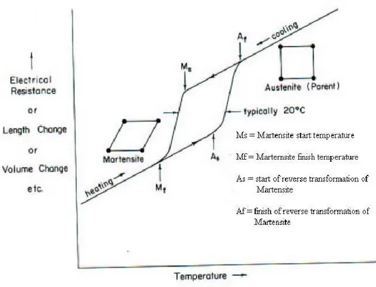
The physical properties of Austenite and Martensite are different. Therefore as the phase transformation progresses and the transformation point is passed, a variety of property changes occur. Any of these property changes can be used to follow the progression of the phase transformation. There are four significant temperatures that characterize the transformation from Martensite to Austenite and vice versa. Four temperatures indicated by Ms, Mf, As, and Af (Figure 6) refer to temperatures at which the transformation to Martensite starts and finishes, and the temperatures at which the reversion to Austenite starts and finishes, respectively. There is a
16
hysteresis associated with this phase transformation (martensitic transformation). Stated alternatively, the transformation temperatures differ upon heating and cooling during the martensitic transformation. The magnitude of the hysteresis varies from one alloy system to another, and has typical values ranging from 20ºC to 40ºC. Microscopically, hysteresis can be attributed to friction associated with the movement of twin-related Martensite boundaries.
Figure 6 Hypothetical plot of property change versus temperature for a martensitic transformation occurring in SMA
One of the many mechanical properties that change during the phase transformation is the yield strength. The martensitic structure deforms by moving twin boundaries. These twin boundaries are quite mobile. Martensite therefore has low yield strength. Austenite, on the other hand, deforms by dislocation generation and movement. Only a certain amount of Martensite can deform based on this twin movement process and once this limit is exceeded, the material will again deform elastically and eventually yield the second time by an irreversible process (movement of dislocations). The resulting unusual tensile behavior is indicated in Figure 7. In Figure 7, the plateau refers to the thermal hysteresis, which means that both Martensite and Austenite are controlled by the frictional stress of the twin boundaries. It is the yield strength ratio between the Martensite and Austenite that controls the ratio of resistances to reversible and irreversible deformations (twin movement to slip). In shape memory alloys, it is important to have this ratio as high as possible in
17
order to recover the most amount of the deformation. Typical values of these ratios are 0.1 to 0.2 (Duerig 1990).
Figure 7 Typical stress-strain curve for a twinned martensite material
1.2.4 The origin of Shape Memory Effect
Martensite is generally of a lower symmetry phase than Austenite. Therefore there are several ways by which Martensite can be formed out of Austenite. However there is only one route by which the Martensite formed will revert back to Austenite. Shape memory effect can be explained in a very simple manner by a 2D geometrical concept depicted in Figure 8 (Duerig, 1990). Upon cooling from Austenite Figure 8(a), the self-accommodating variants of Martensite Figure 8(b) are formed. During the application of stress (deformation), the twin boundaries migrate and therefore result in a biased distribution of Martensite variants Figure 8(c). It is however important to note that no matter what the distribution of Martensite is, there is only one possible austenitic structure that these variants can revert back to. Therefore the martensitic variants must return back to the original undeformed shape after reverting back to Austenite. Therefore the shape accommodation due to a twin boundary movement can only be supported by a low symmetrical martensitic structure, and when the more symmetric Austenite structure is returned, the twinning deformation must also disappear.
18
Figure 8 Shape memory shown microscopically: Austenite (a) is cooled to form twinned Martensite (b) without undergoing a shape change, then is deformed by moving twin boundaries (c). Heating either state (b) or (c) will return the originally austenitic
structure and shape.
Once the shape has recovered at Af there is no change in shape when the specimen is cooled to below Mf and the shape memory can be reactivated only by deforming the martensitic specimen again. In other words, the shape memory effect is a onetime only occurrence and therefore it is frequently referred to as the one-way shape memory effect. Typical recoverable strains for most SMAs are about 7%, while some of them can recover strains up to 10%. Among the many alloys that exhibit SME, only the Cu-Zn-Al, Cu-Zn-Ni, and Ti-Ni alloys are presently of commercial importance.
19
1.2.5 Stress-induced Martensite and Superelasticity
So far shape memory effect has been considered to be both thermal and mechanical. The Martensite is initially formed during cooling and is then deformed below the Mf temperature, and then heated to above the Af temperature to cause the shape to recover. This means that shape memory is caused by heating. There is also another type of shape memory that is dependent upon temperature, which is referred to as superelasticity. It is a known fact that the formation of Martensite is a thermoelastic process, which means that a decrease in temperature between Ms and Mf results in a slight growth of existing martensitic plates and the nucleation of new ones. However when the temperature is incrementally raised the newly nucleated plates disappear and those which grew slightly on incremental cooling correspondingly shrink back a little. Stated alternately, there is equivalence between temperature and stress: a decrease in temperature is equivalent to an increase in stress, and these both stabilize Martensite. The Martensite is also crystallographically reversible, which means that the reversion of a given plate upon heating is just the reverse of the formation process, i.e., the plates undergo a backward shear as it disappears. Normally, on cooling, the Martensite forms under
Ms if a stress is applied and the so-formed Martensite is called as stress-induced Martensite (SIM). The driving force for the transformation is, in this case, mechanical rather than thermal. Above Ms the stress required to produce SIM increases with increasing temperature, as shown in Figure 9.
The variation in stress required to produce SIM increases linearly with temperature above Ms,.
Figure 10 shows that the extrapolated stress drops to zero at the temperature Ms. The linear variation of stress to induce Martensite as a function of temperature obeys the Clausius-Clayperon equation, and is written as
dP
H
dT
T V
(1.1)where P is the pressure, T is the temperature, and ΔH is the transformation latent heat and ΔV is the volume change of the phase transformation. Equation 1.1 has been traditionally used by chemists (Duerig, 1990), but metallurgists, on the other hand, use the Clausius-Clayperon in the following form:
20
Figure 9 Stress-strain curves for Cu-Zn single crystal loaded in tension above Ms
21 0 s
d
H
dM
T
(1.2)where ΔH and T have the same interpretation as for Equation 2.1, and σ, Ms, and ε0 are the applied stress, the shifted Ms temperature and the transformational strain resolved along the direction of the applied stress. The difficulty to stress induce Martensite continues to increase with temperature until
Md, above which the critical stress required to induce Martensite is greater than the stress required to move the dislocations. Therefore the temperature range for SIM is from Ms to Md. For a number of SMA systems, the agreement in the temperature dependence of the stress to form SIM according to the Clausius-Clayperon equation is quite striking. The equation works equally well for the non-isothermal case, i.e., the case where temperature was held constant while the stress needed to form Martensite was measured.
Superelasticity occurs when a material is deformed above As, but still below Md. In this range, Martensite can be made stable with the application of stress, but becomes unstable upon removal of stress. Figure 11 shows a superelastic stress-strain curve for a Cu-39.8%Zn SMA. The upper plateau corresponds to the formation of Martensite under stress whereas the lower plateau represents SIM when the load is released (Duerig, 1990). Note that 9% strain is fully recovered during unloading, and can be viewed as a mechanical shape memory effect. When the SIM is formed for a single crystal Cu-Zn shape memory alloy only a single variant is formed during the application of stress. This results in an elongation (or shape change) which is fully recovered upon release of the applied stress. This situation is unlike the case of thermal Martensite, there is no overall net shape change accompanying the formation of various variants of Martensite.
1.2.6 Mathematical background for martensitic transformation
Experimental evidence from optical, SEM (Scanning Electron Microscope), and TEM (Transmission Electron Microscope) observations indicate that during a MT, a line and surface is converted to another line and surface. This conversion can be represented mathematically by a matrix operator. The parent (Austenite) and martensitic phases are of different microstructures. A coordinate transformation must be performed to mathematically explain the MT. Linear algebra is used to perform such a transformation. During a coordinate transformation, the mathematical operator will itself undergo a transformation.
22
Figure 11 Stress-strain curve for a Cu-Zn shape memory alloy, loaded above the As temperature and then unloaded, shows superelastic behavior.
Application of a coordinate transformation to a vector results in the transformation of the mathematical operator based on a similarity transformation. Wayman and Duerig (1990) have discussed the mathematics of the similarity transformation.
A martensitic crystal is formed from the parent phase through a diffusionless transformation. This type of a transformation is well explained for the FCC to BCT (Base Centered Tetragonal) transformation in steels, Figure 12. Generally a FCC twin has a BCT lattice with an axial ratio of 1.414. Martensite in general has a ratio close to one. This is possible when the Z axis is contracted and X and Y axes are elongated, according to the mechanism first proposed by Bain. Even though the mechanism differs for different type of SMA systems. A Martensite can always be created from a parent phase by a combination of elongation, contraction and shear along certain directions (Otsuka, 1998). Since MT is a diffusionless transformation, there exists a one-to-one relation between the parent and the martensitic phase.
23
Figure 12 Mechanism of FCC-BCT (or BCC) transformation Bain strain. XYZ represent the crystal axes in the parent FCC lattice, while XYZ represent the axes in the BCT Martensite.
1.2.7 Phenomenological theory of the martensitic transformation
The crystallographic characteristics of the martensitic transformation are well understood by the phenomenological crystallographic theory. The theory requires that the MT consists of the following components
1) a lattice deformation B, as a result of the formation of Martensite from the parent phase, 2) lattice invariant shear P2 (as a result of twinning, slip, or faulting),
3) a lattice rotation R.
Theory requires that the shape memory strain produced by the MT consists of a lattice invariant strain and is homogeneous macroscopically. It consists of a shear strain parallel to the habit plane and an expansion or contraction normal to the habit plane. The shape memory strain can also be represented as follows (Wayman and Duerig, 1990).
24
The crystallographic theory has been so far successfully applied to Au-Cd, Pt, Ni-C and Fe-Al-C alloys with a good correlation between experimental and theoretical results. The theory when applied to other SMA systems, does not provide overall agreement between experiment and theory.
1.2.8 Thermodynamic aspects of the martensitic transformation
The MT can be explained based on a thermodynamic analysis, as it is driven either by stress or temperature. There is heat interaction between the SMA specimen and the surroundings and specific temperatures characterize the phase transition. Even though these temperatures can be determined by the DSC (Differential Scanning Calorimetry) methods, a thermodynamic analysis will provide an insight into characteristics unique to SME like hysteresis, superelasticity, one-way effect, rubberelasticity, and two-way effect.
A gas can be liquefied by the application of a suitable pressure. Similarly, a phase transition from the parent phase to Martensite can be induced by the application of a stress. A thermodynamic analysis explains thermal and mechanical effects on the SME. Thermodynamics is a good tool to perform calculations on the thermal implications of the stress induced phase transition. It also explains the reversibility of the phase transition in certain SMAs and highlights energy contributions that control the hysteresis phenomenon.
Gibbs theory of thermodynamic stability is used to describe the phase transition under the consideration that the alloy system is in equilibrium. Based on the above consideration it is evident that Gibbs theory is not suitable for systems not in equilibrium, for which fluctuations are amplified to generate new structures. An MT can be considered to be a succession of several equilibrium states and Gibbs approach based on free energy can be used. The thermodynamic analysis is based on work and methodology presented in the work on SMAs by Trochu (1996).
The MT is a solid state transformation and a thermodynamic analysis, based on internal variables such as the latent heat of the phase transformation, enthalpy, and entropy for a single crystal of SMA, is presented in this Section. Derivation of the classical Clausius-Clayperon equation that relates stress and temperature is also presented. The analysis is conducted for a single crystal of SMA, because this facilitates the investigation of the SMA specimen as a thermodynamic system with only one component.
25 1.2.8.1 Thermally induced phase transformation
In this particular case, the martensitic phase transformation is thermally induced. The SMA crystal has energy interactions with its surroundings in the form of heat and work and this can result in an increase, or decrease, in the internal energy. The change in internal energy undergoing a heat transfer with its surroundings, or doing useful work, can be written in thermodynamic terms as follows:
dE dQ dW
(1.3)where E is the internal energy, dQ is the heat exchange between the SMA crystal and its surroundings, and dW is the work accomplished as a result of dQ. Assuming the phase transformation as a reversible heat transfer situation and using the second law of thermodynamics the following relation is obvious and valid:
dQ TdS
(1.4)where T is the temperature and dS is the change in entropy of the SMA crystal. According to thermodynamic convention, work done by a system is positive and energy transfer into the system is also positive. Keeping this in consideration and also from the assumption that that work done by the crystal is a hydrostatic work, an expression for the work done can be written as
dW
pdV
(1.5)where p is the pressure and dV is the change in volume. From Eqs. (1.4) and (1.5),
dE TdS pdV
(1.6)All properties that are used in the thermodynamic analysis are extensive and refer to per unit mass basis of the SMA crystal. As E, S, and V are difficult to control during experimentation, additional thermodynamic potentials in the form of enthalpy H and the Gibbs free energy G have to be introduced. They can be defined in terms of E, S, T and V as follows (Trochu, 1996):
H
E pV
(1.7)and
26
Differentiating Eqs (1.7) and (1.8), and rearranging the results for dE and dG we have
dH TdS Vdp (1.9)
dG Vdp SdT (1.10)
The entropy S and the pressure p are natural variables that appear in the expression for the increment of enthalpy dH. At constant pressure, dH corresponds to the amount of heat transferred between the crystal and the surroundings. The temperature T and pressure p constitute natural variables in the expression for dG. These natural variables are easier to control during experimental procedures and hence are very useful in thermodynamic analyses of the phase transformation. Thermodynamic equilibrium is achieved when dG = 0 . If the temperature T is altered at constant pressure, then a plot of the Gibbs free energy as a function of temperature T can be constructed and can be represented schematically, in Figure 13.
Figure 13. Evolution of free energies for the parent and martensitic phases at constant stress
The slope of GP (T, p) represents the entropy of the parent phase and is a function of temperature.
For small intervals of the temperature T, GP can be considered to be a constant and the following
relation between the enthalpy, temperature T, and entropy S can be written
P P P
G H TS (1.11)
Similarly, an expression for the martensitic phase can also be written and is of the form:
M M M
27
From Figure 13 it can be noted that at a particular temperature T=T0, phase transition from the
parent phase to Martensite as well as the reverse transformation are possible without any hindrance. Also, at T<T0, Martensite is stable and at temperatures T>T0 Austenite is stable. Hence T0 is also
called as the transition temperature and can be determined from the Gibbs free energies of the two phases. The expression for the transition temperature can be written as
0 . P M P M H H H T S S S (1.13)
In this particular analysis if the interaction between the two phases is to be taken into account, then an additional variable is to be considered. This variable, fM , is the fraction of Martensite that has
been transformed into Austenite. The entropy, S , in such a situation is given by the expression (Trochu, 1996)
(1
)
P MS
f S
fS
(1.14)On multiplying Eq. 1.14 by Eq. 1.13 and differentiating the result with respect to S, we obtain:
0 0( )
M P
T dS T S S df dQ (1.15)
Where dQ is the latent heat of the phase transformation and experimentally can be determined by the use of a DSC.
1.2.8.2 Stress induced phase transformations at constant temperature
When a stress is applied to a single crystal of SMA in the parent phase, it gives rise to a response that can be written mathematically as follows:
0 ij ij
dW V
d(1.16)
where V0 is the volume of the SMA crystal, dW is the mechanical work done as a result of the
applied stress σij , and εij is the incremental macroscopic strain. The change in internal energy for
such a system can be written as
0 ij ij
,
dE TdS V
(1.17) and also an expression for the change in enthalpy dH can be written as0 ij ij
dH TdS V
d (1.18)28 0
dE TdS V d
(1.19) 0dH TdS V d
(1.20) respectively.The pressure p is atmospheric and hence a constant and also the volume change is negligible for the martensitic transformation. Similarly, an expression for dG can be written in the form
0
dG SdT V d (1.21)
Deformation is more difficult to control than stress and, therefore, it is necessary to introduce a generalized form of the Gibbs free energy G* into Eq. 2.21, which becomes
*
0
G
G V d
(1.22)Differentiating Eq. 1.22 with respect to G we obtain
*
0 0
dG dG V d
V d
(1.23)Substituting Eq. 1.21 into Eq. 1.23 and rearranging we get
*
0
dG SdT V d
(1.24)At constant temperature T and stress σ, thermodynamic equilibrium is characterized by dG*0. For
a single crystal SMA specimen subjected to a uniaxial stress, the expressions for the Gibbs free energy for the parent and the martensitic phases can be written as
* 0 * 0 (G ) , (G ) P P P P M M M M H S T V H S T V
(1.25)The stress and temperature imposed on the SMA are assumed to be the same for both of the phases, with the thermodynamic potential being different as a result of the phase transformation. An
29
* *
0 .
G H T S V
(1.26)
During phase transformation ΔG* = 0 is reached and the latent heat of phase transformation Q(σ) can be defined as follows:
0
( ) .
Q TdS H V d (1.27) Rearranging terms in Eq. 1.27 the classical relation between stress and temperature as a result of the phase transformation can be written as follows:
0 . d S dT V (1.28)
Equation 1.28 is also called as the Clausius-Clayperon equation and is of vital importance in thermomechanical analysis. Equation 1.28 relates stress and temperature during a phase transformation. In Eq. 1.28, ΔS and Δε are characteristic parameters for a given SMA. The Clausius-Clayperon equation shows a linear dependence between stress and temperature when ΔS is independent of temperature. When the stress reaches a critical value given by σ0 (T) , a volume
change equal to V0dε occurs. An interaction between the parent and the martensitic phases was
not taken into account in the previous analysis. That is, the parent and the martensitic phases are not independent. The transformation is discontinuous, is produced in a step by step with each individual step taking less time than the total time for the transformation to occur. Let fM be the molar fraction
of Martensite crystal during transformation. The variation of the internal energy of the transformed fraction increment dfM can be written as
0 .
M M M
Edf T Sdf V d df
(1.29)
The crystal gains elastic energy and interfacial energy at the interface between the two phases during the parent to the MT. These energies can be restored during the reverse transformation. The portion of heat loss due to the internal friction cannot be recovered and taking into considerations all these different energies, the change in internal energy can be written as follows:
0
,
i el
30
where dEel is the reversible part of the interfacial and elastic deformation energies, TdSi is the
irreversible heat loss, V0σdε is always positive as it represents dissipated energy, and
* 0 * , , el i c R i dG SdT V d dE TdS dG dG dG dW
(1.31)where dGc is the increment of absorbed or dissipated energy during the chemical reaction, dGR is the
reversible energy of non-chemical nature associated with the transformation, and dWi is the energy
dissipated that represents irreversible energy loss.
1.2.9 Overview of applications of shape memory alloys
1.2.9.1 SMA applications in the biomedical field
1.2.9.1.1 SMA applications in the orthodontic field
The first application of NiTi in the biomedical field dates back to 1975 when Dr. Andreasen from Iowa University made the first implantation of an orthodontic device exploiting the pseudoelastic property of the alloy (Andreasen e Hilleman 1971). NiTi wires, which are in austenitic phase at the temperature of the buccal cavity, have been successfully used for years in fixed orthodontic treatment with multibrackets (Torrisi 1999), Figure 14.
31
In particular, pseudoelasticity is exploited for generating constant force, after positioning of the wire into the brackets, for wide dental movements. During the insertion phase, the physician deforms the wire thereby inducing a transformation phase from austenite to single-variant martensite; once positioned, the material tries to go back to austenite phase (stable at the buccal cavity temperature) and hence tries to recover the original shape following the descendent path of the force-displacement curve in austenitic phase, which is characterized by a wide plateau. The shape memory effect, and in particular the “constraint recovery” effect, is exploited for producing wires that are in martensitic phase during the positioning into the buccal cavity: deformed during the insertion into brackets, they try to recover the original undeformed shape whenever the patient ingests hot food or drinks. Because the recovery is prevented, the wires exert light forces on the teeth for the entire period in which the temperature is above the normal values (Airoldi, Riva e Vanelli 1995). SMA wires are also inserted into steel palatal arches Figure 15 (a); a palatal arch is mounted on superior molars and applies rotating, expanding and torquing forces. The presence of parts made by SMA exploiting pseudoelasticity allows the device to apply lighter (with respect to the forces generated by an arch completely in steel) and constant forces. Pseudoelastic behavior is also exploited for producing orthodontic distractors (Idelsohn, Pena e Lacroix 2004) Figure 15 (b), which are used for solving the problem of teeth overcrowding in the mandible district: after a mandibular symphyseal distraction osteogenesis, the device is applied in order to produce an expansion of the mandible. Also in this case the use of SMA assures tensile forces nearer to the physiological values and constant in time.
Figure 15 (a) Palatal arch. (b) Orthodontic distracters.
32
Figure16 Endodontic file.
These forces create stress conditions that improve the tissue growth and hence teeth movement into the correct position. In the endodontic field (the dentistry branch that studies the problems related with the tooth pulp and the tissues surrounding the root of a tooth), the medical treatment foresees the use of rotating devices (files) working inside the root canal to perform a perfect cleaning and shaping: the decontaminated canal is then filled with an inert filling. The files must have good flexibility and a cutting blade. The first devices were from steel and used manually. At the end of the 80’s, a great improvement in the technique was given by the introduction of NiTi: the pseudoelastic behavior assured a high flexibility, recovery of deformation (without production of plastic strain), and limitation of the applied force, thus allowing the use of NiTi files Figure16 with a rotating motor (Sattapan, Palamara e Messer 1993).
1.2.9.1.2 SMA applications in the orthopedic field
The stress generated by SMA, when the shape recovery is constrained during heating from Mf to Af, is exploited for fracture treatment by using orthopedic staples (Dai, et al. 1993) or plates. The device Figure 17, characterized by a temperature Af lower than that of the body, is deformed in the martensitic phase (T ≤ Mf ≤ Af ) and hence inserted into the body where the fracture is present. The body temperature induces the shape memory effect; because of the constrained recovery, the plates induce a constant stress, consequently joining the two fractured pieces.
33
Figure 17 (a) NiTi plate for mandible fracture; (b) staple before and after distraction.
In Figure 18 (a), an application for the treatment of mandible fracture is reported (Laster e MAcBean 2001). NiTi rods are also inserted in devices for correcting scoliosis (Schmerling, Wilkor e Sanders 1976); in this case, the constrained recovery is used for modifying vertebrae relative position. It has also been proposed (Duerig 1990) to exploit the shape memory effect for designing a spinal vertebrae spacer with a rounded shape to be used on behalf of the damaged intervertebral disc.
Figure 18 (a) staple for fixing a frontozygomatic fracture [27]; (b) spinal vertebrae spacer.
By exploiting the material’s high deformability in martensitic phase, it is possible to modify the device shape for facilitating the insertion between the vertebrae where, being that the temperature is
34
higher than Af, the device recovers to its original shape Figure 18 (b). Recently, intraspinal implants exploiting pseudoelasticity have been studied for stabilizing spinous processes in the case of vertebral discs (Contro, et al. 2005).
In orthopedics treatments, the SMA properties are also exploited during the physiotherapy of partially atrophied muscles (Machado e Savi 2003). Gloves for promoting the movements of hands were developed by positioning SMA wires in correspondence of the fingers. In this application the two-way shape memory effect is exploited; heating or cooling, the wires contract or stretch and accordingly the hand is closed or opened.
Another recent application of SMA in the orthopedic field refers to SMA foams. Porous NiTi, characterized by low density, high surface area, high permeability, high strength (important to prevent deformation or fracture), relatively low stiffness (useful to minimize stress shielding effects), high toughness (essential to avoid brittle failure), and by a shape-recovery behavior (facilitating implant insertion and ensuring good mechanical stability within the host tissue), is particularly interesting for osteointegration processes.
1.2.9.1.3 SMA applications in the vascular field
Besides the orthodontic field, the SMA devices are broadly applied in the vascular one. In particular, the introduction of the shape memory alloys boosted the development of mini-invasive techniques where the pathology is treated by the percutaneous insertion of the device rather than surgical intervention. The first vascular SMA application was the venous “Simon filter”, Figure 19 (a), used to prevent emboli in patients unable to tolerate anticoagulants. It can be inserted thanks to the shape memory effect (Lipscomb e Nokes 1996).
35
The device is produced in the open conFiguretion with a NiTi alloy having Af equal to the body temperature, which depicts it in the martensitic phase at ambient temperature. Thus, during the crimping of the device on the catheter, a residual deformation is present as-consequence of themartensitic transformation from multivariant to single-variant phase, which allows the device to be closed and easily placed in the catheter. A saline solution flows in the catheter to keep the temperature low during its insertion into the body. When the catheter is in position, the filter is released, the saline solution is stopped and the body heat induces the martensite-austenite transformation with recovery of the device’s original shape. The filter is now able to block the possible clots of the blood stream. In literature, it is possible to find a variety of different filters (Asch 2002)which use the pseudoelastic effect; similarly in this situation, the open conFiguretion at ambient temperature is already in a stable austenitic phase; the crimped device, as soon as it is released in the body, recovers to its original open conFiguretion.
Other common devices are those used to close ventricular septal defects (Thanopoulos, et al. 1998), which are characterized by the presence of an atrial hole in the surface between the two low pressure chambers of the heart. The surgical method includes an invasive and hazardous approach via a thoracotomy and manual suture of the hole. The alternative of using a mini-invasive approach is appealing. The device is made of SMA wires and of an impermeable polyurethane membrane Figure 19 (b). The insertion procedure consists of three steps: (i) positioning of the catheter with the crimped device through the superior vena cava, (ii) positioning of the catheter tip in the left atrium and release of half of the device, and (iii) completion of procedure via release of the remaining part of the device in the right atrium. According to the device typology, both shape memory and pseudoelastic effects are utilized.
NiTi alloys are also used in numerous applications of the self-expandable vascular stents. Stents are metallic “nets” (built by means of laser cutting stainless steel, Cr-Co, or NiTi alloy tubes) which open a stenotic vessel (obstructed by atherosclerotic deposits), therefore allowing restoration of the blood stream to peripheral tissues (Tragy, et al. 2003). For the stainless steel and Cr-Co alloy stents, the stenting procedure consists of: (i) crimping the stent in the terminal part of a catheter which has an inflatable balloon, (ii) insertion of the catheter through a surgical incision in a vessel and positioning of the catheter through the vessel in the stenotic region, (iii) inflation of the balloon with expansion of the stent which pushes against the arterial vessel and (iv) deflation of the balloon and removal of the catheter. Following elastic recoil, the stent remains in an open conFiguretion (plastic deformation) and counteracts the natural vessel contraction, which would tend to reocclude the vessel. For the NiTi stent, the stenting procedure consists of: (i) crimping the stent into the catheter
36
in the austenitic phase (Af is lower than body temperature) by means of a protective sheath, (ii) insertion of the catheter as stated above and (iii) removal of the sheath and expansion of the stent which tries to recover its original shape thereby enlarging the stenotic vessel. During this phase, the inverse transformation from martensite to austenite occurs, which is due to the martensitic instability at a temperature higher than Af . The advantage of the self-expandable stent with respect to the stainless steel one is that it does not need balloon expansion which possess the risks of further damage of the vascular tissue due to its inflation, it does not require an overexpansion to account for the elastic recoil, and, when positioned, it exerts on the artery a constant force (due to the plateau) unless the artery does not try to occlude the device. The disadvantage, in case of calcified plaques, is that the stent is not able to bring the vessel lumen to the original healthy dimensions.
Self-expandable stents are used to treat atherosclerotic lesions in the coronary arteries, the carotid arteries, and in the peripheral arteries, such as the iliac and femoral arteries Figure 20. The pseudoelasticity property is very important in the peripheral stent which is subjected to possible squeezing manoeuvres such as muscle contractions.
Figure 20 Example of SMA stents: (top right) coronary stent, (top left) carotid stent, (bottom left) femoral stent.
Another successful application of the NiTi alloys is the use of the stent-graft for the treatment of abdominal aortic aneurisms (AAA) (Carpenter, et al. 2000). An aneurism is a permanent dilatation of a portion of an arterial vessel because of vessel wall alterations. For the treatment of this pathology, in the last years, in conjunction with classical surgical techniques, endovascular techniques, with the percutaneous insertion of stent-graft, gained popularity. This means that the stent-graft is easily crimpable on a catheter, sufficiently flexible during the insertion phase, and able to recover its original shape anchoring to the aorta once it has been positioned correctly. All of these
37
features are present in the pseudoelastic behaviour of the NiTi alloys. This is an explanation of the numerous different prostheses present on the market (Cattaneo 2006), Figure 21.
A recent and very promising field of SMA application is related to the stenotic and regurgitant cardiac valves (Coats e Bonhoeffer 2007). The common adopted strategy to overcome this pathology consists of surgical valve replacement with a mechanical or biological valvular prosthesis. A thoracotomy is present in this substitution eliciting possible surgical complications. The use of mini-invasive techniques allows the surgeon to reduce, in a significant way, the risks of the procedure. For this reason, there are different companies which are developing percutaneous devices to treat mitral, pulmonary, and aortic valvular diseases.
Figure 21 Example of stent-graft in NiTi alloys.
38
For the aortic position, for example, CoreValve developed a device Figure 22 (a) which consists of a biological prosthesis made with bovine pericardium mounted and sutured on a self-expandable stent. The insertion procedure consists of positioning the device with a specifically designed catheter without the need for removal of the native valve. The self-expandable stent shows a diamond-like cell design with struts at different lengths and thicknesses to optimize the expansion to a nonregular shape Figure 22 (b).
In the last years, the ever more extended use of NiTi in cardiovascular applications has pointed out the problem of its fatigue behaviour (Pelton, Kusnezov e Carman 2008). In particular, for the treatment of peripheral arterial diseases with self-expandable stents, there is a growing concern about observations of fractures during follow-up procedures. Fractures are mainly detected in superficial femoral artery and this is probably related to the combination of pulsatile forces, due to systolic/diastolic pressure cycles, and nonpulsatile forces (torsion, compression, extension, and flexion), due to leg movements, which characterize the stent solicitations. The study of NiTi fatigue life is a current and very complex problem: the nonlinear nature of the pseudoelastic behaviour entails that conventional fatigue life theory is difficult to apply; the strong influence of the production treatments on the material characteristics requires fatigue specimens having the same dimensions and production treatments of the device under study; design, material, and surface conditions together play an important role for the definition of NiTi alloy stent fatigue and durability. For all these reasons, great efforts are currently directed to a more rigorous understanding of NiTi fatigue behavior and to the design ofNiTi medical devices that aremore fatigue resistant.
1.2.9.2 SMAs applications in the civil engineering field
1.2.9.2.1 Research on the damping properties of SMAs
Using SMAs for passive structure control relies on the SMA’s damping capacity, which represents its ability to dissipate vibration energy of structures subject to dynamic loading. As reviewed in the last section, the damping capacity comes from two mechanisms: martensite variations reorientation which exhibit the SME and stress-induced martensitic transformation of the austenite phase which exhibit the superelasticity. The energy dissipation of the widely-used Nitinol superelastic SMA wires was investigated (Dolce e Cardone, Mechanical behaviour of shape memory alloys for seismic application 1. Martensite and Austenite NiTi bars subjected to torsion 2001), (Piedboeuf e
39
Gauvin 1998). Dolce and Cardone (Dolce e Cardone 2001) investigated the superelastic Nitinol wires subjected to tension loading. They observed the dependence of the damping capacity on temperature, loading frequency and the number of loading cycles. It is found that the mechanical behavior of the wires is stable within a useful range for seismic application. Also, they suggested that the austenite wires should be pretensioned for larger effectiveness of energy dissipation. Piedboeuf and Gauvin, (Piedboeuf e Gauvin 1998), reported that the influence of ambient temperature on the damping capacity of the superelastic Nitinol wires can be negligible. Gandhi and Wolons (Granghi e Wolons 1999)proposed using a complex modulus approach to characterize the damping capacity of superelastic SMA wires for convenient integration with structure dynamics. A superelastic SMA wire demonstrates the damping capacity not only under tension loading, but also under cyclic bending. In 2000, Song et al. presented his effort to predict the energy dissipation in SMA wire under pure bending loading. His numerical results showed that the energy dissipated by the superelastic SMA wire is highly sensitive to its diameter; in detail, the thicker the SMA wire, the more energy was dissipated. Recently, as large cross-section-area SMAs become available, studies on the properties of SMA bars or rods have attracted more attentions (Dolce e Cardone, Mechanical behaviour of shape memory alloys for seismic application 1. Martensite and Austenite NiTi bars subjected to torsion 2001). As discovered by Liu et al. (Liu, Xie e J.V. 1999), the damping capacity of a martensite Nitinol bar under tension–compression cycles increases with increasing strain amplitude, but decreases with loading cycles and then reaches a stable minimum value. Dolce and Cardone (Dolce e Cardone, Mechanical behaviour of shape memory alloys for seismic application 1. Martensite and Austenite NiTi bars subjected to torsion 2001) compared the martensite damping and austenite damping of Nitinol bars subjected to torsion. They found that the damping capacity of the martensite Nitinol bar is quite a bit larger than that of the austenite Nitinol bar, although the prior cannot remain at its highest value as the residual strain accumulates. They also noticed that the martensite bar’s mechanical behavior is independent of loading frequency and that of the austenite bar slightly depends on the frequency. This implies that both martensite and austenite Nitinol bars can work in a wide frequency range and have a good potential for seismic protection. An overview of the damping capacity of martensite SMAs is presented in (Humbeeck 2003).