POLITECNICO DI MILANO
Master in Computer Science and EngineeringDipartimento di Elettronica, Informazione e Bioingegneria
A DVFS-Capable Heterogeneous
Network-on-Chip Architecture for
Power Constrained Multi-Cores
Supervisor: Prof. William FORNACIARI
Assistant Supervisor: Dr. Davide ZONI
Master Thesis of:
Andrea MARCHESE
Student n. 823353
Abstract
In the multi-core era, the Networks-on-Chip (NoCs) emerged as the de-facto interconnect due to their scalability and flexibility. Moreover, they strongly influence the power consumption and performance of the entire platform, thus representing a key component to be optimized. In this scenario, sev-eral proposals in the literature presented Dynamic Voltage and Frequency (DVFS) capable NoCs to trade the power and performance metrics. However, the NoC traffic is highly variable due to the different phases an application crosses during its own execution. Last, the coherence protocol greatly con-tributes to the traffic shape. In a nutshell, the NoC traffic shape is mainly due to the coherence protocol, while the specific application only influences the traffic volume. Few seminal works discussed coherence-aware DVFS schemes for NoCs. This thesis presented a novel DVFS-capable heterogeneous NoCs. A fine grain analysis of the traffic composition enabled a further optimization of the DVFS actuation. The proposed NoC is capable to optimally balance the power and performance at low, medium and high traffic. Thus deliv-ering an holistic solution that is roughly application independent. This is achieved thanks to a load balancer module that can route the traffic to the different implemented physical networks. The mechanism observes the traffic load and adjusts the frequency of each physical NoC to optimally match the objective function. The novel NoC has been integrated in the Gem5 full-system simulator and compared with the baseline NoC and a state of the art DVFS-capable methodology. Results are extracted considering a 64-core architecture executing the Splash2 benchmarks. Results show that the pro-posed NoC almost provides the same performance of the performance-aware baseline NoC with an energy reduction of 30% and one third less resources.
Acknowledgments
First of all, I would like to thank my thesis advisor Prof. William Forna-ciari and my thesis supervisor Dr. Davide Zoni for their patient guidance, enthusiastic encouragement and useful critiques of this research work. They consistently allowed this paper to be my own work and conveyed to me the passion to do research.
I would also like to extend my thanks to the people of the HIPEAC Research Group for their help and their support in running this thesis.
I wish to thank my family, my mother Rosanna, my father Gianni and my brother Matteo, for their support, their continuous encouragement during all these long six years, always by my side through all obstacles. I would not have done it without them.
Finally, special thanks should be given to all my friends because they have always been with me to celebrate the success and to make me smile even when the sky was darkened.
Contents
1 Introduction 1
1.1 The Cache-Coherent Multi-Cores: Architecture and
Applica-tions . . . 2
1.2 Problem Overview . . . 3
1.3 Goals and Contributions . . . 7
1.4 Background . . . 8
1.4.1 DVFS: Dynamic Voltage and Frequency Scaling . . . . 13
1.5 Thesis Structure . . . 18
2 State of the Art 19 2.1 The DVFS-aware NoC Design . . . 19
2.2 State-of-the-Art on multi-core Simulator . . . 21
2.3 Heterogeneous Network-on-Chip Design . . . 23
2.4 Cache coherence impact on traffic . . . 26
3 Novel Heterogeneous NoC Design 29 3.1 Architecture pillars . . . 30
3.2 Design key points . . . 32
3.3 The Heterogeneous NoC Architecture . . . 37
3.3.1 Exploit the heterogeneous network architecture . . . . 37
3.3.2 The Load Balancer . . . 38
3.4 The Adaptive Policy . . . 40
3.4.1 Quality of service related issues . . . 42
3.4.2 The DVFS smart switching policy . . . 43
3.5 Simulation Framework Overview . . . 45
4 Results 47 4.1 Simulation Setup . . . 47
4.1.1 Policy comparison . . . 48
4.2 Performance Analysis . . . 50
4.3 Energy Analysis . . . 52
4.4 Energy Delay Product Analysis . . . 54
4.5 Sensitivity Analysis . . . 55
5 Conclusions and Future Works 59 5.1 Future Works . . . 60
List of Figures
1.1 Frequency impact on performance . . . 5
1.2 Total traffic volume . . . 5
1.3 Performance overhead for each coherence protocol . . . 7
1.4 The baseline router architecture . . . 8
1.5 Message structure in NoC . . . 9
1.6 The baseline router pipeline . . . 11
1.7 Comparison between baseline and speculative router pipeline . 13 1.8 The impact of the frequency to the delay . . . 14
1.9 Logic view of FIFO4ALL architecture . . . 16
1.10 Impact of Resynchronizer . . . 17
1.11 FIFO Resynchronizer scheme . . . 17
3.1 Overview of the proposed NoC architecture. . . 30
3.2 Total Injected Flit comparison for cache coherence protocol. . 34
3.3 Flits distribution. . . 35
3.4 Different execution phases. . . 36
3.5 Simulation framework overview. . . 46
4.1 Performance results . . . 51
4.2 Energy results . . . 52
4.3 Energy Delay Product Results . . . 54
4.4 Performance results considering variance values . . . 55
4.5 Energy results considering variance values . . . 56
List of Tables
2.1 State-of-the-Art simulation frameworks. . . 22 3.1 The allocation of the cache coherence messages to the Virtual
Network classes . . . 31 4.1 Experimental setup: processor and router micro-architectures
and technology parameters . . . 49 4.2 The Splash2 subset. . . 49 4.3 The simulated architectures . . . 50 4.4 Percentage of time that the auxiliary network is on for the
applications evaluated. . . 52 4.5 Different variance values for the proposed architecture. . . 58
Acronyms
BW = Buffer WriteCMP = Chip Multi-Processor CPU = Central Processing Unit DMA = Directory Memory Controller
DVFS = Dynamic Voltage and Frequency Scaling EDP = Energy Delay Product
FIFO = First In First Out
GTCM = Global Traffic Congestion Manager GPU = Graphics Processing Unit
HPC = High Performance Computing LT = Link Traversal
LA = Link Allocation
NAVCA = Non Atomic Virtual Channel Allocation NTC = Near Threashold Computing
NIC = Network Interface Controller NoC = Network-on-Chip
PE = Processing Element PLL = Phase-Locked Loop PNET = Physical Network RC = Route Computation SA = Switch Allocation SaF = Store and Forward ST = Switch Traversal
VA = Virtual-Channel Allocation VC = Virtual Channel
VCW = Virtual Channel Wormhole VFI = Voltage Frequency Island VNET = Virtual Network
VCT = Virtual Cut-Through WH = Wormhole
Chapter 1
Introduction
“Sometimes it is the people no one can imagine anything of who do the things no one can imagine.”
Alan Turing
The multi-core architectures emerged to provide a better power perfor-mance trade-off with respect to single core processors. However, the multi-core revolution pushed to the limit the on-chip bus-based solutions, thus highlighting the Networks-on-Chip (NoCs) as the de-facto on-chip intercon-nect. The NoC provides better scalability and flexibility properties than bus architectures, while its great impact on the power, performance and area metrics imposes a cunning design to deliver a successful architecture. The adoption of the on-chip networks makes the multi-cores widespread in differ-ent market segmdiffer-ents, ranging from the High Performance Computing (HPC) to the embedded systems. The rest of this chapter introduces the objectives, the research area and the background of the thesis. In particular, Section 1.2 discusses different multi-core classes to better focus on the architecture sub-set that are considered in this work. The goals and contributions of the thesis are detailed in Section 1.3, while Section 1.4 provides a background on the main architectural blocks discusses in the thesis, i.e. the NoC, the cache co-herence protocols and the Dynamic Voltage and Frequency Scaling (DVFS) mechanism. Last, the structure on the thesis is devoted in Section 1.5.
1.1. The Cache-Coherent Multi-Cores: Architecture and Applications
1.1
The Cache-Coherent Multi-Cores:
Archi-tecture and Applications
The computer architects always tried to increase the clock frequency and the architectural complexity at each generation to match the performance level foreseen by the Moore’s Law. The hit of the so called power wall at the beginning of 2000s, started the transition from single-cores to multi-cores with the final objective of increasing the performance per watt metric. This is essential to keep the pace with the Moore’s Law, while constraining the power consumption. The multi-cores provide a flexible architectures where different applications can truly execute in parallel. Moreover, such architec-tures allow different supply voltage values and clock rates to different parts of the architecture to further increase the performance per watt ratio.
The multi-cores range from the embedded to the High Performance Com-puting (HPC) segments. The HPC architectures execute computationally demanding applications from a wide range of domains trying to match the capacity computing paradigm. The capacity computing paradigm aims at executing the maximum number of applications while ensuring the best per-formance per watt ratio. Conversely, low power requirements dominate the embedded multi-cores mainly due to their battery-powered nature. Embed-ded multi-cores are still general purpose architectures while the low power requirements impose a different design methodology compared to the HPC platforms. Last, the accelerators are becoming a widespread multi-core so-lution [40] to boost the computation of some specific tasks inside a bigger application. Usually the multi-core accelerators implement simpler in-order, GPU-like CPUs, that are coupled with a simplified non-coherent cache hierar-chy. The non-coherent cache hierarchy represents the key different between general purpose multi-cores and the accelerator, task specific multi-cores. The absence of the coherence protocol greatly reduces the generated traffic, while the programmer has to manually ensure the coherence. On the other hand, cache coherent multi-cores provide as easier to program platform, that is generic with respect to the executed applications.
The applications represent an additional design dimension for multi-cores, since they drive the design of new computing platforms. Considering the multi-core scenario, different applications are expected to run concurrently on the same hardware, each of them with its specific set of requirements and constraints. Moreover, each application should believe to be executed
1.2. Problem Overview
in isolation with respect to all the other running tasks. The requirements from different applications can be contrasting to each other and can require the same hardware resources to be fulfilled, thus highlighting the well known resource contention problem [8]. The scenario is further complicated by the end users, that claim the same user-experience regardless if the application is executed on a smartphone, a tablet or desktop platform. For example, current smartphones are expected to smoothly run demanding graphic ap-plications with the same user-experience of a laptop. Furthermore, single-and multi-threaded applications can execute on the same multi-core single-and each application traverses different phases during its execution, e.g. memory-bound, CPU-memory-bound, thus stressing the platform resources in an unbalanced and time-dependent fashion.
This thesis targets the general-purpose, cache coherent multi-cores with particular emphasis on the embedded domain, where the power requirements can further narrow the design space. Different multi-threaded tasks are evalu-ated with different execution phases, to strengthen the proposed architecture.
1.2
Problem Overview
Considering a general-purpose, cache-coherent multi-core, the design space is huge. Thus, it is difficult to provide a system-wide optimized architecture ac-counting for the computational subsystem side by side with the interconnect and the memory hierarchy. Such optimized design is further complicated by the different application classes that are executed on the platform. Each class of applications has different requirements that can possibly contrast with the requirements of other applications. Moreover, the possibility to have appli-cations of different classes that concurrently run on the same architecture represents a possible scenario that has to be accounted during the architec-tural design stages. In a nutshell, the possibility to have a virtually infinite variety of applications that can be executed on the multi-core makes the application-based optimization unfeasible. The resulting architecture would be a set of accelerators, each of them specifically designed for an application or a class of applications. Thus, such a solution is not viable for general pur-pose multi-cores. However, the optimization of the multi-core architecture to fit a broad class of applications still represents a key objective for design architects. In particular, the cache hierarchy and the interconnect greatly impact the performance and power metric. Thus their optimization can not
1.2. Problem Overview
be neglected during all the design stages.
The Dynamic Voltage and Frequency Scaling (DVFS) mechanism has been extensively exploited in the computer architecture field for decades to optimize the power-performance metric. The DVFS allows to reduce the operating voltage and frequency when less computational power is required with a net power reduction. Conversely, both voltage and frequency can be increased to offer more computational power when required by the running applications. The adoption of the DVFS mechanism coupled with a suitable policy to steer it has been explored in CPUs for decades. The multi-core revolution moved the DVFS exploitation to the emerging NoC architectures. Several proposals optimize the NoC power-performance trade-off by means of the Dynamic Voltage and Frequency Scaling actuators and companion poli-cies [55, 33, 47], while others focus on the design of a more efficient NoC micro-architecture [48, 31, 32, 3].
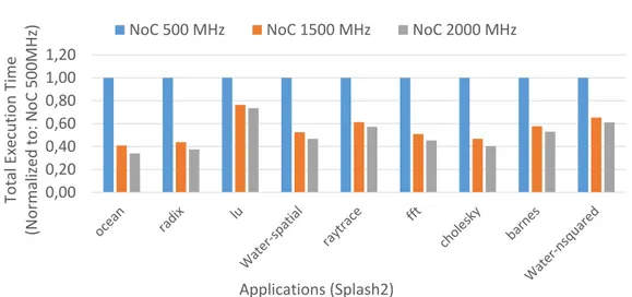
Considering the Splash2 benchmarks [46], Figure 1.1 shows the applica-tion performance impact due to the NoC frequency. Results are collected from an 8x8 2D-mesh topology using 2GHz out-of-order CPUs. Each bench-mark has been simulated with different fixed NoC frequencies - 500MHz and 2GHz - and a strong variations in its execution time has been observed. For Example, the OCEAN application shows an execution time of 82.33ms and 27.94ms when the NoC frequency is set at 500MHz and 2GHz, respectively. The frequency reduction directly reduces the performance of the architecture. On the contrary, frequency increase improves the performance but with a non negligible impacts on the power consumption.
On the other hand, the coherence protocol represents an orthogonal de-sign dimension to improve the power-performance trade-off in the multi-core. An optimized coherence protocol increases the data re-usability in the cache hierarchy with benefit for both the performance and the power consump-tion. Considering the interconnect, the coherence protocol is responsible of the imposed traffic pattern and shape. Conversely, the applications can only impact the absolute traffic volume, that is actually application dependent.
The cache coherence protocol greatly contributes to the generated traf-fic, thus impacting the overall system performance as well as the absolute traffic volume. Different coherence protocols have been proposed to trade the system-wide performance and the imposed traffic to the interconnect. Figure 1.2 shows the generated traffic by three different coherence protocols
1.2. Problem Overview 0,00 0,20 0,40 0,60 0,80 1,00 1,20 Total Execution Time (Normalized to : NoC 500MHz) Applications (Splash2)
NoC 500 MHz NoC 1500 MHz NoC 2000 MHz
Figure 1.1: Frequency impact on performance.
0 100 200 300 400 500 600 700 Tr af fic V olum e [Bits] x 100000000 Application (Splash2)
MESI MOESI MOESI HAMMER
Figure 1.2: For each considered Splash2 benchmarks, the traffic volume is reported for three different coherence protocols.
1.2. Problem Overview
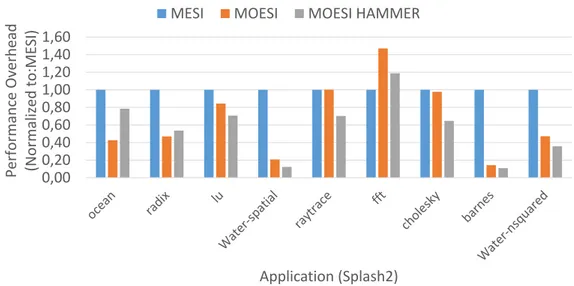
considering the Splash2 [46] benchmarks. Conversely, Figure 1.3 presents the performance information using the same coherence protocols and benchmark set. The MESI represents the reference coherence protocol. The MOESI enhances the MESI protocol by adding the Owned (O) state. Two different MOESI-based coherence protocols have been compared. The MOESI ex-ploits the so called directory to retrieve the coherence information, while the MOESI-hammer implements a broadcast-based mechanism to get the same information.
Results in Figure 1.2 and Figure 1.3 highlight the MESI as the less suitable coherence protocol for multi-threaded applications, mainly due to the lack of the Owned (O) state. The Owned state enhances the performance in case of data ping-ponging effects between two L1 caches. Thus, each application shows a huge imposed traffic with poor performance (with MESI) if com-pared to the results obtained with the other coherence protocols. However, the trade-off between the traffic volume and the performance clearly emerges when MOESI and MOESI-hammer protocols are compared. The MOESI represents the MESI enhancement using a directory to keep the coherence. Conversely, the MOESI-hammer still implements the protocol optimizations over the MESI protocol, while it exploits a broadcast mechanism to retrieve coherence information instead of a directory. To this extent, the MOESI is traffic-aware due to its ability to get the information on the most up to date copy of each required data from a specific point in the cache hierarchy. On the other hand, the MOESI-hammer broadcasts to anyone in the multi-core to get the same information with a net traffic increase. The MOESI-hammer is faster in getting such information on average, thus offering better perfor-mance, mainly due to the possibility to directly get the required information, while the implementation of a directory represents and additional point of indirection.
The coherence protocol strongly influences the traffic volumes in the in-terconnect. Besides the traffic volumes can be seen as an indirect power con-sumption metric for the interconnect. This thesis primarily focuses on the embedded multi-cores, thus the MOESI directory-based protocol is used in the rest of this work instead of the MOESI-hammer, mainly due to the power consumption constraints that are imposed at the platform level. Finally, the thesis aims to extract valuable information from the MOESI coherence pro-tocol to steer the DVFS mechanism.
1.3. Goals and Contributions 0,00 0,20 0,40 0,60 0,80 1,00 1,20 1,40 1,60
Performance Overhead (Normalized to
:MESI)
Application (Splash2)
MESI MOESI MOESI HAMMER
Figure 1.3: Performance overhead considering three cache coherence protocols. Results are normalized to the MESI.
1.3
Goals and Contributions
This thesis presents a novel heterogeneous NoC architecture for cache-coherent multi-cores. The traffic burstiness characteristics as well as the traffic infor-mation are exploited to design the NoC as well as to control the DVFS mechanism implemented at NoC level. In particular, the thesis encompasses the three main contributions:
• Relationship between the interconnect load and the coherence protocol generated traffic - The intricate relationship between the data required by the applications, the implemented coherence protocol and the im-pact that these two aspects have on the actual traffic on the intercon-nect have been investigated. Moreover, the insights of such an analysis are still valid to complement and extend the proposed interconnect. • Heterogeneous NoC design - Two different, heterogeneous NoCs are
used to route different traffic types. Such NoC design emerges from the traffic information analysis as well as the latency- and bandwidth-sensitive phases that the application traverses during its execution. • Application-aware DVFS mechanism and policy - Using the knowledge
1.4. Background
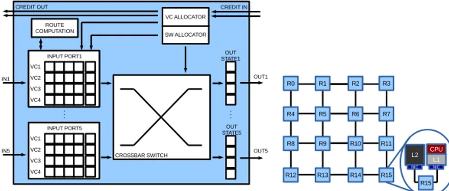
Figure 1.4: The baseline router architecture. It is presented a virtual-channel, wormhole, credit-based router highlighting its main components and how core and caches are connected to the relative router.
between the NoC frequency and the system-wide performance, the pro-posed NoC architecture can decide the best physical channel where the traffic has to be routed to get an optimal power performance trade-off.
1.4
Background
The Network-on-Chip is a scalable and reliable interconnect that allows nodes to exchange data. A node can be both a CPU or a part of the mem-ory subsystem. The Noc is made of routers, links and Network Interface Controllers (NICs). Routers manage routing of data and coherence packets into the network. The NIC is the component that allow the communication between a node and a router. Two routers are connected using simple links or eventually using a router and a NIC.
Figure 1.4 depicts a Chip Multi-Processor (CMP) which relies on a 4x4 2D-mesh NoC as interconnect. Routers take care of the communication be-tween the various CPUs and memories. Each router is connected to some other through a link. For example R15 is connected to router R11 and R14 through two different links. R15 is connected also to a L1 and a L2 cache memories; L1 is also connected to the CPU. Communication between them is supported by the NICs.
From the communication view point the various nodes exchange mes-sages, which typically are requests and responses generated by the coherence protocol. Traditionally, the NoC splits each message in multiple packets.
1.4. Background
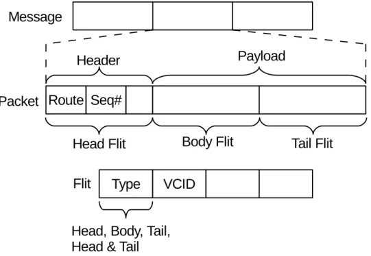
Figure 1.5: Message structure in NoC. There are presented the message, its division in packets and, furthermore, in flits highlighting the headers essential information.
Then each packet is eventually split in multiple flits to better utilize the NoC resources. These different levels of granularity are shown in Figure 1.5. Data and coherence packets have different dimension: Data packet are usu-ally composed by 9 flits, instead coherence control packets are usuusu-ally single flit packets.
The NoC itself is characterized by some features: the layout topology, the routing scheme, the switching mechanism, the flow control mechanism and the router architecture. The NoC topology defines the way routers are inter-connected to each others and how memory and CPU blocks are attached to the NoC. The most common topologies used in NoC are mesh [14], concen-trated mesh [3], hybrid bus based [15, 45] and high radix [22]. In Figure 1.4 it is shown a 2D-mesh network where the routers are connected in a matrix form.
Given a specific topology the routing algorithm defines each source-destination path inside the NoC. Routing algorithms can be deterministic [3] or adaptive [20, 18, 19], based on their capacity to alter the path taken for each packet.
1.4. Background
The most used deterministic routing scheme in 2D-meshes is XY routing where a packet first goes in the X direction and then in the Y one.
The switching mechanism is in charge of the transmission of the infor-mation between the input and output ports inside a router. Some switching mechanisms are Store-and-Forward (SaF) [29], Virtual cut-through (VCT) [27], Wormhole switching (WH) [34] and Virtual-Channel Wormhole switching (VCW) [13]. The most commonly used switching technique is VCW, which associates several virtual channels with a single physical channel, overcoming blocking problems of WH.
The flow control is a mechanism responsible of managing the advance of the flits between the routers. All the switching techniques that use buffers need a mechanism to communicate the availability of buffers at the down-stream router. Three mechanism are used: Credit-based, Stop & Go and Ack/Nack [14]. The most commonly used in NoCs is the Credit-based one and with this mechanism every output port knows the exact number of free buffers and the number of slots available for every buffer in the downstream router.
A message provides the node-to-node communication, but when it tres-pass the NIC it is divided into NoC’s basic data structure: the packet. A packet is considered split in multiple atomic transmission units called flits. The first flit of each packet is the head flit. A body flit represents an interme-diate flit of the original packet while the tail flit is unique for each packet and closes the packet. There is another particular case of packets called single flit packets and they are composed by a single head/tail flit.
After this general explanation of the NoC it is now presented in Fig-ure 1.4 presents the baseline architectFig-ure of a wormhole NoC’s router that is considered in the thesis.
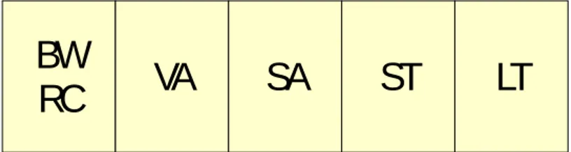
A wormhole router supporting VCs and VNETs is considered. It is a standard 4-stage pipeline, i.e. Buffer Write/Route Computation (BW/RC), Virtual Channel Allocation (VA), Switch Allocation (SA), and Switch Traver-sal (ST). A single cycle for the Link TraverTraver-sal (LT) is assumed as shown in Figure 1.6.
The considered NoC implements the VNET mechanism to support the coherence protocol, preventing the traffic from a VNET to be routed on a different one. When a head flit arrives to the input port of the router it has to pass through the 4 pipeline stages before traversing the link. First, it is stored in the VC buffer (BW) which has been reserved by the upstream
1.4. Background
Figure 1.6: The baseline router pipeline. The figure shows the baseline NoC router 4-stages pipeline with the addition of the link traversal.
router, and the output port is computed (RC). Then, it competes in the VA stage to reserve an idle virtual channel in the selected output port. Notice that assigned VCs belong to the set of VCs associated to the VNET of the packet. Once the VA succeeds, head, body and tail, competes in packet order for a crossbar switch path (SA). Finally, each winning flit in the SA has to pass the ST and LT before reaching the next router. Note that tail and body flits pass through fewer stages since they reuse resources and information reserved by the head flit (i.e., VC and RC). n The NIC is another NoC component that provides communication between the nodes and the network. The NIC wraps up the requests from the cores as messages suitable for the NoC and rebuilds them at destination. When a message is taken from the NIC queue it is split into packets and each one of them is divided into flits. Then the whole packet divided in flits is allocated in a VC. Here all the flits will compete for the link allocation and then they will be sent to the next router.
The entity that creates the traffic in chip-multiprocessor (CMP) systems is the cache coherence protocol, thus influences the NoC behavior. CMPs typically implement a cache coherence protocol on top of the network (shared-memory CMP system). The protocol guarantees coherency and consistency when sharing memory blocks between multiple cores (processors). Indeed, the protocol keeps the coherency among different copies of the same memory block replicated through different L1 and/or L2 cache memories. The cache coherence protocol (in a shared-memory CMP system) is the main driver for the network. NoCs can be differentiate between systems with shared cache structures and systems with private cache structures. While the L1 cache is usually private for each processor, the L2 can be private or shared. In a system with private L2 caches each processor has its own L2 cache block and in case of a L2 miss, a request is sent to the memory controller. Later, the
1.4. Background
request will be forwarded to another L2 cache or to memory. In a system with shared L2 caches the four L2 blocks are shared by all processors, and each cache block is mapped on a particular L2 bank. In case of a L1 miss, a request is sent to that bank, that can be located in the same tile or in one of the other tiles. This way the four banks of the L2 cache are part of a single L2 cache physically distributed among the tiles.
Two are the main different cache coherence protocols developed: Direc-tory and Hammer, each one generating a different kind of network traffic.
In the Directory protocol directory information is associated with each cache block, including information about which core, if any, has a valid copy of the block, whats the current state of the block, and whether or not the block is dirty. In case of a miss in the private cache a request is sent to the home node, which forwards it to the owner core or sends the block to the requester depending on the blocks state. If L2 caches are private, the home node is located in the memory controller; if L2 caches are shared, each L2 bank is the home node to a given subset of cache blocks. Since the directory has to be stored in the home node, space overhead is the main drawback of this protocol. Cache misses generate low network traffic: in case of a read miss, two or three messages are sent: the request message to the home node, eventually a forwarded request to the owner core, and finally a message with the block; in case of a write miss, more messages may be sent since the home node has to invalidate the cores that share the block, if any.
In the Hammer protocol no additional information associated with the cache block is needed. When a cache miss occurs, a request is sent to the home node (which is located in the memory controller if L2 are private or in an L2 bank if L2 are shared, as in the Directory protocol). The home node broadcasts the request to all other cores and sends an additional off-chip request to the main memory. The cores answer by sending the block or, in case they do not have a valid copy, an acknowledgment message; so, if the system has N cores, the requesting core has to wait for N messages: N-1 data or acknowledgment messages from the other cores and one data message from the memory. If at least one core sends a data message, the memorys data is considered stale and ignored. The Hammer protocol generates even more traffic than the Token protocol, since broadcast operations are performed at every cache miss and all cores have to answer. All protocols use MOESI states: extension of MESI protocol, restrict write-back of data from cache to main memory.
1.4. Background
Routing (RT) VC Arbitration (VA) Switch Alloc. (SA) Crossbar
Routing (RT) VC Arbitration (VA) Speculative SA Crossbar 4-Stage Router 3-Stage Router
STAGE 1 STAGE 2 STAGE 3 STAGE 4
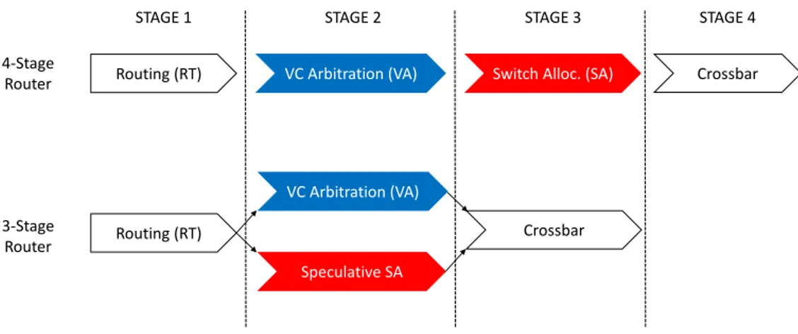
Figure 1.7: Comparison between baseline and speculative router pipeline.
Non atomic virtual channel allocation (NAVCA) - Usually VNET-based NoCs with Virtual Channels offer only atomic buffer allocation schemes, i.e. at most one packet can store flits in a buffer at the same time. However, a scenario with a mix of long and short packets, imposes a minimum buffer depth to face performance penalties due to the credit round trip time. In this scenario, short packets are usually single flit packets, since the link width is designed to transmit them quickly. As a consequence, short packets coupled with the atomic VC allocation impose a waste of buffering space, i.e. all the slots except the first are never used. The possibility to allocate a packet to a non empty-buffer using the Non Atomic Virtual Channel Allocation design improves both performance and buffer utilization.
Speculative Pipeline Optimization - We have used an optimized pipeline with only three stages as shown in Figure 1.7. This optimized pipeline has been also used in literature [37]. A speculative virtual-channel router arbitrates between output VC and switch bandwidth in parallel, this speculating that a VC will be allocated for the packet. If the speculation turns out to be incorrect, the SA speculation is wasted. As the switch allo-cator prioritizes non-speculative requests over speculative ones, there is no adverse impact on throughput.
1.4.1
DVFS: Dynamic Voltage and Frequency Scaling
Power consumption is one of the major design issue in multi-core processor development. Moreover, the CPU can no longer be considered the unique1.4. Background
freq=1GHz
freq=500MHz
Figure 1.8: The impact of the frequency to the delay.
contributor due to the core, since the interconnect contribution to the over-all energy budget is relevant. The DVFS has been exploited for power-performance optimization in cores [43] memories [10] and interconnect [24]. It provides a flexible and scalable way to jointly optimize power and per-formance, by addressing both static and dynamic power and dynamically adjusting the voltage and frequency values.
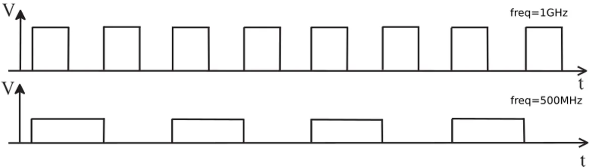
Dynamic Voltage and Frequency Scaling is an effective mean to reduce power consumption in CMOS chips. The power dissipation in digital Com-plementary Metal Oxide Semi-conductor (CMOS) circuits occurs due two main sources. Static power arising from bias and leakage current, it’s de-pendent to the process and design technologies. Dynamic power is the other form and it get down from charging and discharging of voltage saved in node capacitances in the circuit. The dynamic power P depends on voltage V and frequency f . Formula (1.1) shows how dynamic power P depends on voltage V and frequency f .
P ∝ f V2 (1.1)
The voltage value reduction implies the increase of the gate delay, thus reducing the operating frequency. Consequence of this relation cause a delay in transmission as shown in Figure 1.8.
The dynamic frequency change of different communication blocks requires a resynchronization support to avoid metastability issue and guarantee sig-nal integrity. The globally asynchronous locally synchronous (GALS) design scheme allows to partition the design into different so-called voltage and fre-quency island (VFIs) considering signal resynchronization at VFI boundaries. Each VFI can work at its own speed, while the communication across dif-ferent voltage islands is guaranteed through the use of FIFO resynchronizer.
1.4. Background
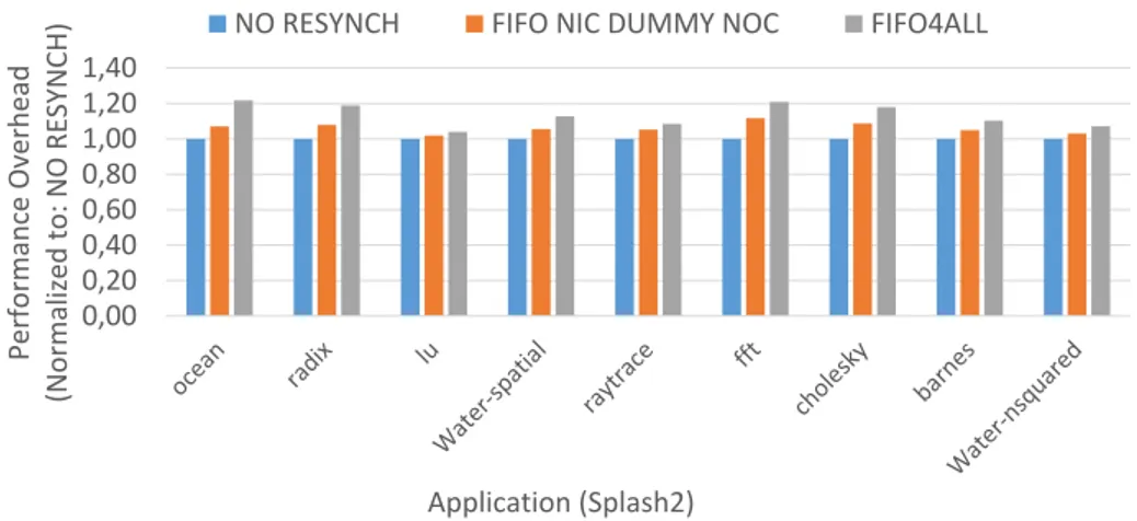
This provides the flexibility to scale the frequency and voltage of various VFIs in order to minimize energy consumption. Design NoCs with multi-ple VFIs involves a number of critical steps: granularity, i.e. the number of different VFIs, and chip partitioning into VFIs needs to be determined since design time; also VFI partitioning need to be performed together with assigning of the supply and threshold voltages and the corresponding clock speeds for each island. Moreover, create islands of nodes running at differ-ent frequencies has some disadvantages: locally replicated DVFS controller and DC-DC converters cause area and power overhead, moreover resynchro-nization at the crossing between multiple frequency domains involves major performance losses. To allow reliable data transfers between components op-erating at different frequencies, a new component called FIFO resynchronizer must be insert between each Network Interface and router to avoid metasta-bility issues. It is composed of a FIFO buffer with two clocks, i.e. write and read clocks, and two other signals, i.e. isFull and isEmpty, to monitor its current status of producer and consumer. This implementation allows to safely read and write it avoiding metastable states [36]. Figure 1.11 de-picts the implemented FIFO resynchronizer between a router and a Network Interface Controller (NIC) that connect the CPU to the NOC.
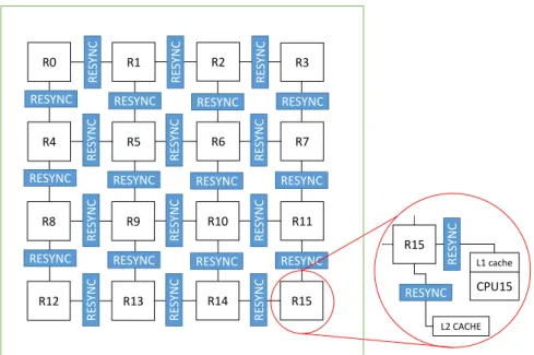
In particular, considering a 8x8 2D-Mesh with 64 cores running at 2 GHz and the Splash2 applications, the introduction of the FIFO resynchroniza-tion model between NIC and the router introduces a performance penalty within 12%. It means that each physical Network can be his own frequency. Moreover, inside each Network each router must be at the same frequency (FIFO NIC DUMMY NOC architecture). If the architecture design imposes total flexibility, each router can work at different frequency. In this case, a resynchronizer must be placed between each router and each NIC with a performance degradation within 22% with an average value of 14%. We call this architecture FIFO4ALL. Figure 1.9 shows FIFO4ALL structure with a detailed view of resynchronizer position inside each node and between each router. Figure 1.10 reports the performance overhead considering the Splash2 benchmarks on an 8x8 NoC. Two resynchronization scheme have been tested. Results are normalized against the NO RESYNCH NoC implementation. Based on the results, our methodology supplies FIFO Resynchronizer for DVFS implementation only at NoCs border, allowing each Physical Network to run at its own frequency but inside each network each router must be at the same frequency. The goal is minimize the resynchronizer impact on both
1.4. Background R0 R1 R2 R3 R4 R5 R6 R7 R8 R9 R10 R11 R12 R13 R14 R15 RESYNC RESYNC RESYNC RESYNC RESYNC RESYNC RESYNC RESYNC RESYNC RESYNC RESYNC RESYNC RE S YNC RE S YNC RE S YNC RE S YNC RE S YNC RE S YNC RE S YNC RE S YNC RE S YNC RE S YNC RE S YNC RE S YNC R15 L2 CACHE L1 cache CPU15 RESYNC RE S YNC
Figure 1.9: Logic view of FIFO4ALL architecture. The FIFO NIC DUMMY
NOC only implements resynchronizers at the NoC border. No resynchronizers are implemented between routers.
power and performance.
In order to be able to change interconnect frequency at runtime, an ac-tuator module must be introduced. The acac-tuator is a PLL that allows to accurately select the router frequency. The PLL introduces timing and per-formance overheads. In particular, when a frequency increase is required, the voltage regulator is activated in advance to properly set the voltage in order to support the new frequency that the PLL is imposing. On the contrary, when the frequency is moved down the PLL immediately starts decreasing the frequency, while the voltage will follow it, without imposing any addi-tional delay except the PLL response time.
It is worth noticing the resynchronization delay cannot be recovered in any way and its totally independent from the implemented DVFS policy. Due to this fact our methodology exploits a per-PNET DVFS. Independently from global or per-router implementation, metrics used to choose when change Voltage and Frequency during run time execution are essential to achieve the best power-performance trade-off.
1.4. Background 0,00 0,20 0,40 0,60 0,80 1,00 1,20 1,40 Performance Overhead (Normalized to : NO RESYNCH) Application (Splash2)
NO RESYNCH FIFO NIC DUMMY NOC FIFO4ALL
Figure 1.10: The performance impact due to different resynchronizations scheme. Results are normalized to NO RESYNCH.
NIC R0
isFull isEmpty
Network Link with FIFO resynch
Data Link Data Link
isEmpty isFull
Credit Link with FIFO resynch
Credit Link Credit Link
Clock 0 Clock 1
isFull isEmpty
Network Link with FIFO resynch
Data Link Data Link
isEmpty isFull
Credit Link with FIFO resynch
Credit Link Credit Link
Figure 1.11: FIFO Resynchronizer between a Network Interface Controller (NIC) and a router. Four different FIFOs per each NIC-router pair are required, since unidirectional links are used for both data packets and flow control information.
1.5. Thesis Structure
1.5
Thesis Structure
The rest of the thesis is organized in five chapters. Chapter 2 describes the state of the art in DVFS, Heterogeneous Network applied to NoCs and cache coherence impacts on traffics. Chapter 3 provides a detailed description of methodology and its novel contributions. Chapter 4 details the methodology validation providing the results considering a realistic environment. Chap-ter 5 points out some future works on the NoC architecture.
Chapter 2
State of the Art
“You can’t connect the dots looking forward; you can only connect them look-ing backwards. So you have to trust that the dots will somehow connect in your future. You have to trust in something - your gut, destiny, life, karma, whatever. This approach has never let me down, and it has made all the difference in my life.”
Steve Jobs
This chapter summarizes the state of the art that is of interest in this thesis to improve the NoC power-performance trade-off. The literature is huge and different techniques and guidelines emerged to optimize the DVFS and the NoC architecture. The DVFS-aware NoC designs are discusses in Section 2.1. A review on the available, DVFS-aware simulation frameworks for NoCs is provided in Section 2.2. Section 2.3 discusses the architectural NoC optimizations to improve both power and performance. Last, Section 2.4 discusses the state of the art on the impact the coherence protocol has on the NoC due to the generated traffic.
2.1
The DVFS-aware NoC Design
Starting from single-core architectures, the DVFS emerged as a practical solution to deliver on-demand computational power to the running appli-cations. With the multi-core revolution, the DVFS mechanism has been extensively exploited in the NoCs to dynamically adapt the platform com-putational power to the application needs to deliver an high-bandwidth, low
2.1. The DVFS-aware NoC Design
latency and power efficient interconnect. The rest of this section discusses both the mechanism and the companion policies proposed in the literature.
[33] explores different router-level policies to dynamically tune the NoC router frequency and optimize the power-performance trade-off. The per-input-port buffer utilization is the metric to decide the frequency to be ap-plied to the whole router. More different policies have been evaluated. All routers operate at a boosted frequency. This helps in enhancing the perfor-mance at low load, with latency traffic, while slightly increasing the power consumption. When the state of the network become congested, the power consumption becomes the key challenge. Hence, the policy throttles the fre-quency/voltage of selected routers using the DVFS mechanism. The novel frequency tuning algorithm reduces the latency and the power consumption in the Noc by a distributed throttling and boosting of the router frequency based on the actual network load. Moreover, a distributed congestion man-agement scheme has been implemented to provide each router with the pos-sibility to signal its load to its neighbors. Thus, [33] provides a complete, distributed per-routed DVFS solution for NoCs.
A router-level, control-based methodology for DVFS-aware NoCs has been presented in [55]. The input buffer utilization is still exploited as the contention metric to decide the frequency to be applied to routers. An ana-lytical model of the network traffic has been developed to better characterize the DVFS controller. The final solution exploits two different observations. First, the flow balance assumption equation expresses the connection between contention at current and next time instant. The router contention is defined as the sum of the number of flits in the input buffers and is also the quantity that has to be measured at runtime to close the control loop. A proportional controller has been implemented to tune the router frequency at run-time. It is worth noticing, the methodology eventually allows the user and/or the OS to change the high level power-performance modes, i.e. to trigger perfor-mance oriented or power saving system behaviors. Moreover, [55] presented a complete analysis on the impact the resynchronization scheme has on the overall methodology in terms of performance and power overheads. The im-pact of the resynchronization mechanism in DVFS capable NoCs has been further investigated in [53]. To this extent, the solution in [55] has been proved to overcome all the threshold-based DVFS policies like the one pro-posed in [33]. However, the used of a router-level DVFS scheme is overkilling in terms of performance and power due to the required resynchronization
2.2. State-of-the-Art on multi-core Simulator
scheme.
The thread voting approach proposed in [47] represents an on-chip DVFS technique for NoCs. It is able to adjust the NoC voltage and frequency (V/F) on a per region basis. Each region is composed of a subset of adjacent routers sharing the same V/F level. Considering a per thread voting-based approach, the threads can influence the DVFS mechanism by voting for the V/F level that best suits their QoSs. [47] used the thread performance level, instead of the classic network level parameters to steer the DVFS. The ingoing and outgoing traffic allows to capture the thread communication requirements. Moreover, it allows to monitor the thread data dependencies. The model uses two, thread-level parameters. One is the message generation rate that monitors the average number of outstanding L1/L2 misses. The other is the average number of data sharers for a specific data request. The first points out the per thread average network accesses, while the second reflects the contention on the specific required data. However, this work has a strong impact on the interconnect schema due to the necessity to add a novel in-frastructure that allows the communication between the application threads and the policy controller.
2.2
State-of-the-Art on multi-core Simulator
The software simulation is the de-facto standard to evaluate complex multi-cores. Unlike hardware prototyping, it allows a relatively fast design space exploration. Besides, the obtained results greatly depend on the accuracy of the modeled components. In this scenario, the accuracy in modeling DVFS actuators and resynchronization circuits has a great impact on result relia-bility. The state-of-the-art provides several simulation frameworks but most of these are not accurate enough, providing DVFS and GALS implementa-tions with power and performance behaviors that are far from reality. In particular, the resynchronizer is the hardware component that allows the communication between different VFIs. However, several reviewed simula-tion frameworks do not properly account its performance, power and area overheads, thus providing overoptimistic results that can partially shadow the benefit of the implemented DVFS scheme.
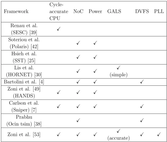
Table 2.1 reports different cycle accurate software simulators with par-ticular emphasis on thier support for DVFS, GALS and NoC. SESC [39] develops a cycle-accurate to simulate of bus-based multicore, but without
2.2. State-of-the-Art on multi-core Simulator
Framework
Cycle-accurate CPU
NoC Power GALS DVFS PLL
Renau et al. (SESC) [39] X Soteriou et al. (Polaris) [42] X X Hsieh et al. (SST) [25] X X Lis et al. (HORNET) [30] X X X (simple) Bartolini et al. [4] X X X Zoni et al. [49] (HANDS) X X X Carlson et al. (Sniper) [7] X X X X Prabhu (Ocin tsim) [38] X X Zoni et al. [53] X X X X (accurate) X X
2.3. Heterogeneous Network-on-Chip Design
support the DVFS and the GALS design. Polaris [42] extends the concept of the NoC simulator providing tools for power and area design space explo-ration. Unfortunately Polaris does not support heterogeneous systems, and the addition of system-level reliability and variability models. SST [25] im-plemented a framework for integrated power, area and thermal simulations, but without providing support for DVFS or PLL models. HORNET [30] is meant to simulate large-scale architecture. The HORNET parallelized sim-ulation engine can scale nearly linearly with the number of physical cores in the processor but does not provide support for any kind of power or area estimation. Bartolini [4] proposes a novel virtual platform for efficiently designing, evaluating and testing power, thermal and reliability closed-loop resource management solutions. [4] also supports the DVFS even if the PLL model is the inaccurate during frequency changes. Sniper [7], creates one of the most accurate distributed parallel simulator for multicores with DVFS projection and power support for CPU. Also in this work GALS support and PLL model are not takes in account into the models. Ocin tsim [38] offers a DVFS aware NoC simulator with support for per node power-frequency modeling to allow the fine-tuning of such optimization techniques early in the design cycle. Power management and different NoC policy are not al-lowed due to the limits of framework that restrict the use only for DVFS exploration purpose. HANDS [49, 53, 44] creates a complete and reliable cycle-accurate simulation framework with support for DVFS and GALS pol-icy integrating accurate PLL models. The simulation flow allows to validate novel DVFS policies and NoC architectures with accurate results in terms of power and performance. Our novel heterogeneous NoC architecture has been tested with the last framework developed by Zoni [53] adding support for Physical Networks with independent DVFS interface for each channels.
2.3
Heterogeneous Network-on-Chip Design
The NoC architectural optimization represents an orthogonal design dimen-sion to DVFS to improve the interconnect power-performance trade-off. Sev-eral proposals addressed the buffer sizing problem to optimize the NoC, since it strongly affects both power and performance [50, 35, 41]. Moreover, the NoC traffic is burst-oriented, thus it is of paramount importance to optimize the implemented NoC resources to minimize the idle time.
2.3. Heterogeneous Network-on-Chip Design
dynamically resize the router buffers depending on the actual length of the stored packets. Buffer slots are assigned on a per flit basis following a daisy-chained list approach. Moreover, [11] proposed a ViChaR-based scheme where the dynamic buffer allocation is done on a per router basis. ViChaR represents the most flexible buffer management solution due to the exploita-tion of a per input port dynamic buffer slot allocaexploita-tion. However, its design complexity motivates the exploration of more lightweight techniques, since both area and power overheads greatly impact the benefit of the methodol-ogy. Besides, [35] highlights that having many VCs with shorter queues is more beneficial than having fewer VCs with a deeper queue when the traffic is low, while the opposite is true on heavy traffic conditions.
Elastistore [41] introduces a lightweight architecture that minimizes the buffering requirements without sacrificing the performance. It makes use of the buffer space in the pipelined channels to reduce the buffer cost. Elastis-tore uses just one buffer slot per VC and a large buffer that is shared between all the VCs in the same input port. Thus, different VCs can dynamically in-crease their buffer size where the only constraints are imposed by the total available, per-input port, shared buffer slots.
[50] exploits the coherence protocol information to dynamically assign different VCs to serve different traffic classes in the NoC. The coherence protocol imposes the minimum number of required VCs that is equal to the implemented message classes. Additional VCs can be implemented to improve the NoC performance. [50] dynamically assigns the VCs to the mes-sage classes depending on the actual NoC traffic, with the only constraint to have al least one VC per message class. The dynamic VC allocation allows to dedicate more channels to the message class with the heavier traffic volume. Moreover, the adaptivity of the mechanism can reconfigure the VC allocation depending on the traffic changes.
[32] proposes an heterogeneous NoC by implementing two different routers. Routers with deeper buffers are implemented in the central part of the 2D-mesh topology, while short buffer routers are used in the topology borders. The methodology also accounts for different combinations of small and big routers while keeping the same bisection bandwidth and the same amount of link resources compared to the baseline homogeneous NoC. HeteroNoc shows that placing big routers along the diagonal provides maximum bene-fits compared to an equivalent homogeneous network in terms of power and performance. However, [32] proposed a design that greatly exploits the XY
2.3. Heterogeneous Network-on-Chip Design
routing algorithm. The XY is a deterministic routing algorithm that is com-mon in 2D-mesh NoC due to its simplicity. Besides, it imposes a severe traffic imbalance between the central and the peripheral parts of the NoC, thus its perfectly fits with the proposed methodology.
On a different but related point, [48] investigated the performance, area and power metrics comparing two different interconnect designs. One im-plements a single NoC that can route all the coherence traffic. The other is composed of multiple physical NoCs, where each of them can route a specific coherence traffic class. The possibility to have multiple physical NoCs can greatly reduce the contention on the shared interconnect resources, since each coherence class of traffic is routed on a physically different NoC. Moreover, it positively affect the overall system performance. Conversely, a single NoC allows a better resource utilization, since the design is globally optimized with respect to all the traffic types at once. However, the higher resource contention can negatively affect the performance.
[3] proposes a dual physical NoC to explore two different traffic distri-bution policies. The first policy uses a specific network to separately route read and write transactions. Moreover, it allows to equally split long packets to the two networks. A second policy splits the traffic between data (long packets) and control (short packets). However, it is not able to correctly balance the traffic between the two physical networks, thus some resources goes underutilized while others are over-utilized.
The heterogeneous NoC design in [31] exploits different traffic distribu-tion informadistribu-tion that have been captured during the applicadistribu-tion execudistribu-tion. An application traverses at least two phases during its own execution. The low traffic phase shows few outstanding cache/memory requests/responses. The high traffic phase shows high network load and contention in the NoC. Such phases are unevenly distributed during the application execution and the possibility to foreseen them can greatly improve the performance. To this extent, [31] presents an heterogeneous NoC design and policy to exploit such a feature. The interconnect is composed of two physical heterogeneous NoCs. Each injected packet is classified as bandwidth or latency sensitive at run-time, then routed to one specific physical NoC. One NoC provides low bandwidth and high frequency, while the other has a wider bandwidth but operates at lower frequency. The application-aware nature of this architec-ture implies a dependency between interconnect and applications.
physi-2.4. Cache coherence impact on traffic
cally separated from the others and optimized to operate within a particular voltage-frequency range. The optimization of each layer to work within a spe-cific frequency range provides a more efficient solution than DVFS in terms of performance and power consumption, since specific cell libraries can be exploited. However, the use of multiple parallel NoCs is costly in terms of area and power compared to the use of a single or dual NoC. [6] developed also an efficient network-layer switch-over mechanism to better support the application execution. All the layer in a region are managed by a hardware based darkNoC Layer Manager (dLM). The collaboration between router components is essential to support the correct exchange between different frequency-level of execution. For this reasons router stack is managed by another hardware component called darkRouter Manager (dRM). dLM and dRM autonomously coordinate each other to realize an efficient mechanism in terms of energy and time overhead, transparent to software and with afore-mentioned requirements. DarkNoC overcomes traditional DVFS solutions in terms of saved energy. However, it shows an area and performance overhead up to 30% and 40% respectively.
2.4
Cache coherence impact on traffic
The coherence traffic exploitation represents a unique source of information to further optimize the DVFS policies at NoC level. However, the concurrent execution of different applications and the traffic mix at NoC level make hard to collect valuable information to be used to optimize the NoC-based DVFS policies. A review of the literature in this direction is investigated in the rest of this section.
[2] presents SynFull, a synthetic traffic generator framework to explore the coherence traffic to later improve the NoC design. SynFull analyzes the cache coherence traffic and the applications behaviors in several directions. Cache coherence messages are a combination of requests and responses. Small control packets and large data packets coexist in the interconnect. The pos-sibility to tight different packets to the same information flow allows to arise further information on the required interconnect resources. Furthermore, some messages are more critical than others. Thus, their fast delivery to des-tination greatly affects the overall system performance. Applications exhibit different phases during their execution, thus imposing a time-dependent NoC load. Exploiting the coherence information that links request and response
2.4. Cache coherence impact on traffic
messages, it is possible to partially foreseen such phases in advance.
[23] presents an NoC traffic prediction scheme based on the cache-coherence communication properties. Starting from the insights in [17], the methodology investigates the correlation between the application synchro-nization points and coherence communication. The methodology is com-posed of two modules. The Coherence Prediction Engine (CPE) extracts the relevant data from the coherence protocol and sends them to the Accumula-tion and Decision Module (ADM). The predicAccumula-tion mechanism is sync-point based, thus it splits the program into different sync-epochs. The characteris-tics of each sync-epoch are stored in the Prediction Table that is part of the ADM. Such information are used to find the correlations between different current sync-epochs and the historical information. The ADM keeps track of all the aggregate bandwidth requirements.
Aergia [16] develops a novel router priorization mechanisms based on the packet slack definition. The Packet Slack is the number of cycles the packet can be delayed in the network without affecting the application execution time. It is used to prioritize the critical packets with low slack values -against the ones having a larger slack value. However, the packet’s slack estimation is challenging, since several timing information of the packet are required at run-time. Aergia exploits a combination of three statistics to overcome such an issue: the L2 cache hit and miss and slack in terms of number of hops.
The coherence protocol information strongly correlate with the imposed network traffic as well as with the required network bandwidth. The ability to correctly predict the traffic shape enables a new interconnect optimization level. However, such prediction is hard due to the intricate nature between different coherence messages that are highly parallel by nature and their cardinality.
Chapter 3
Novel Heterogeneous NoC
Design
“The number one benefit of information technology is that it empowers people to do what they want to do. It lets people be creative. It lets people be productive. It lets people learn things they didn’t think they could learn before, and so in a sense it is all about potential.”
Steve Ballmer
This chapter presents a novel, DVFS-capable, heterogeneous NoC ar-chitecture. The design is complemented with a policy, that exploits the DVFS mechanism and the traffic information to optimize the NoC power-performance trade-off. The proposed solution can thus adapt the NoC chan-nel utilization depending on the run-time traffic conditions. In a nutshell, the proposed design methodology sits on three different pillars:
• exploiting the cache coherence information to optimally route the traffic within the heterogeneous NoC;
• a DVFS mechanism to dynamically adapt the offered interconnect band-width depending on the traffic imposed by the application;
• an interconnect made of multiple, heterogeneous physical NoCs to flex-ibly adapt to different traffic conditions.
The rest of the chapter is organized in five parts. The architecture pillars are provided in Section 3.1. Section 3.2 presents the methodology key concepts.
3.1. Architecture pillars NIC MAIN RD OP AUXILIARY L O A D B A L A N C E R R E S Y N C DVFS CONTROLLER GLOBAL TRAFFIC CONGESTION MANAGER
RD VNET2 VNET1 VNET 0 IP L1D L1I CPU RD OP RD VNET2 IP R E S Y N C IP0 IP1 IPn IP0 IP1 IPn IP0 IPn IP0 IPn OP0 OP1 OPn OP0 OP1 OPn OP0 OPn OP0 OPn R E S Y N C R E S Y N C NIC L1D L1I CPU
Figure 3.1: Overview of the proposed NoC architecture.
Section 3.3 discusses the exploitation of such key concepts in the novel in-terconnect. Section 3.4 presents the policy and the DVFS mechanism. Last, Section 3.5 overviews several use case scenario.
3.1
Architecture pillars
Figure 3.1 shows the architectural implementation of the novel NoC archi-tecture. Our architecture focuses on data intensive contention management providing an heterogeneous network with two different Multiple Physical Net-works (PNET). Each Physical Network is designed to work with specific traf-fic scenarios. The main network is specialized for single flit packet and light data traffic. In this network there are three different virtual networks to avoid deadlock as imposed by the coherence protocol. Each Virtual Network manages a different coherence message subset, as detailed in Table 3.1. The auxiliary network implements one single Virtual Networks and manage the long data packets flow during high contention phases. The DVFS controller provides an efficient frequency and voltage scaling on the auxiliary network. The GTCM collects traffic statistics from all the interconnect both main and auxiliary NoCs. The GTCM elaborates the received data and manages the behavior of the DVFS controller and the Load Balancer. When the traffic is low and the resources are underutilized, the GTCM reduces the frequency of the auxiliary network at 500MHz. At the same time, the Load Balance does not use the auxiliary network and routes all the traffic to the main
3.1. Architecture pillars
network. On the contrary, when the traffic is high the GTCM allows the Load Balancer to route the long packets to both the main and the auxiliary networks in a round-robin fashion. The GTCM senses the NoC contention level to decide the number of active NoCs. The contention is defined as the pressure on the shared NoC resources due to the injected traffic. The Load Balancer balances the traffic between the main and the auxiliary network at runtime. This helps our scheme to capture within-application variation in latency and bandwidth phases. The DVFS controller imposes the same frequency for all the routers in the NoC in the same network. For this reason, the resynchronizer are places between the Network Interface and the Phys-ical Network but not between each router. The main network also needs a resynchronizer to operate at a different frequency with respect to the CPU. The continuous cooperation between the GTCM, the Load Balancer and the DVFS controller is the key of the proposed architecture.
Controller Message Type Direction VNET
DMA ResponseFromDir From 2
DMA reqTodir To 1
DMA respToDir To 2
L2CACHE L1RequestFromL2Cache To 0
L2CACHE GlobalRequestFromL2Cache To 1
L2CACHE ResponseFromL2Cache To 2
L2CACHE L1RequestToL2Cache From 0
L2CACHE GlobalRequestToL2Cache From 1
L2CACHE responseToL2cache From 2
L1CACHE requestFromL1Cache To 0
L1CACHE responseFromL1Cache To 2
L1CACHE requestToL1Cache From 0
L1CACHE responseToL1Cache From 2
Directory requestToDir From 1
Directory responseToDir From 2
Directory forwardFromDir To 1
Directory ResponseFromDir To 2
Table 3.1: The allocation of the cache coherence messages to the Virtual Network classes
3.2. Design key points
3.2
Design key points
This section describes the main contributions of the methodology, from an abstract viewpoint.
Unbalanced traffics - The cache coherence protocol regulates the packet distribution in the interconnect. In particular, the cache coherence protocol is made of a set of coherence controllers that generate coherence messages to ensure the coherence invariants. Simply put coherence messages falls into two categories: control and data messages. Such messages directly translates into packets that are injected in the interconnect. Furthermore, the Network Interface splits each packet into small pieces called flits. Data packets are composed by 9 flits, instead control packets are single flit. The networks carries both data and control packets. Each protocol imposes a specific type of data packets distribution. The reaction of the protocol to cache miss or a coherence request is based on the adopted mechanism. In this perspec-tive, the number of long and short packets is distributed in different way between every network. Directory based protocols try to reduce the number of cache coherence messages. Conversely broadcast-based protocols produce an higher number of messages due to the lack of the directory. Obviously different behaviors have impact on the NoC traffic shape. Considering a Vir-tual Channel-based NoC, it is extremely difficult to extract per message type information, since all the traffic is mixed into the same physical interconnect. The total number of flits injected in each specific channel class is different for each cache coherence protocol with the same application as shown in Fig-ure 3.2. The MOESI protocol improves the MESI, since it generates lower traffic while ensuring better performance. However, the MOESI is not able to reach the performance of the MOESI HAMMER. The MOESI HAMMER is a broadcast-based cache coherence protocol. Broadcast-based protocols generate a high amount of traffic to improve performance with a not neg-ligible impact on the power consumption. Considering MOESI, MESI, and MOESI HAMMER cache coherence protocols, Figure 3.3 shows that short packets are distributed between all the available channels. On the other hand, long packets always flow throw a single Physical Network. This net-work greatly impacts the total power consumption, since all of its packets are made of multiple flits. By changing the cache coherence protocol a deep impact on traffic shapes is observed. See the difference between standard directory-based MOESI and broadcast-based MOESI HAMMER protocol in
3.2. Design key points
Figure 3.3;
The exploitation of the cache coherence information is essential to allocate the right number of buffers and virtual/physical channels to improve the power-performance trade-off. The proposed architecture sits on the MOESI directory-based protocol. It implements a smart interconnect architecture taking advance of the traffics shape information.
Applications phases - The application behavior is another key factor in the design of DVFS capable interconnect. Each application traverses several phases during its execution. This directly impacts the NoC traffic. Each application shows more alternative different phases as highlighted in Fig-ure 3.4. The memory bound phases are bandwidth-sensitive and require a high NoC bandwidth to process the load/store memory requests from the CPUs. During these phases, the CPU is likely stalled waiting for L2 and memory requests to be served. The application needs a significant band-width from the network to make progress during the memory-bound phases because of a large number of requests that are sent out into the NoC. Thus, the progress is less sensitive to the network latency. On the contrary, the high computational phases are latency-sensitive and need less bandwidth but are more sensible to the network latency. During these phases, the ap-plication only has a small number of outstanding memory requests. The CPU has all the data necessary to progress its execution and the computa-tional throughput is high. During intensive CPU bound periods, resources are underutilized because the coherence traffic is low. Instead, the network load increases during the application memory-bound phases. Each appli-cation has a different combination of CPU-intensive and memory-intensive phases. Latency and bandwidth sensitive phases require different operating frequencies. Latency sensitive phases benefit from a high frequency, despite their lower NoC resource requirements, because a low frequency critically af-fects the performance of the few ongoing coherence messages. On the other hand, the performance penalty is directly proportional to the network con-tention during the bandwidth phases. In this phase, the frequency changes based on the bandwidth requirements thus allows for power reduction, still ensuring a reasonable performance drop. These information can provide an implicit application clustering. The application phases are crucial for an effi-cient DVFS-based NoC design. However, a specific architectural support, to better manage the application phases is essential to boost the performance, while reducing the power consumption.
3.2. Design key points 0 0,2 0,4 0,6 0,8 1 1,2 Total Injected Flit s (Normalized to : PNET1)
MESI protocol- Application (splash2)
PNET0 PNET1 PNET2
0 0,2 0,4 0,6 0,8 1 1,2 Total Injected Flit s (Normalized to : PNET2)
MOESI Protocol - Application (splash2)
PNET0 PNET1 PNET2
0 0,2 0,4 0,6 0,8 1 1,2 Total Injected Flit s (Normalized to : PNET3)
MOESI HAMMER Protocol - Application (splash2)
PNET0 PNET1 PNET2 PNET3
Figure 3.2: A comparison of the total injected flit for each cache coherence protocol. The different number of injected flits is reported for each Physical Network.
3.2. Design key points
SHORT LONG
(a) The ratio between long and short packets express in flits with MESI
PNET0 PNET1
PNET2
(b) Detailed distribution of single flit packet with MESI
PNET0 PNET1
PNET2
(c) Detailed distribution of long packets with MESI
SHORT LONG
(d) The ratio between long and short packets express in flits with MOESI
PNET0 PNET1
PNET2
(e) Detailed distribution of single flit packet with MOESI
PNET0 PNET1
PNET2
(f) Detailed distribution of long packets with MESI
SHORT LONG
(g) The ratio between long and short pack-ets express in flits with MOESI-HAMMER
PNET0 PNET1
PNET2 PNET3
(h) Detailed distribution of single flit packet with MOESI-HAMMER
PNET0 PNET1
PNET2 PNET3
(i) Detailed distribution of long packets with MOESI-HAMMER
Figure 3.3: Flits distribution considering long and short packets as well as the three different protocols.
3.2. Design key points 0 1 2 3 4 5 6 7 Time ×106 0 50 100 150 200 250 300 350 400 450 N° of Flits traffic contention LATENCY BANDWIDTH (a) FFT 0 0.5 1 1.5 2 2.5 3 3.5 4 Time ×106 0 100 200 300 400 500 600 700 800 900 1000 N° of Flits traffic contention LATENCY BANDWIDTH (b) OCEAN 0 1 2 3 4 5 6 7 8 Time ×106 0 50 100 150 200 250 N° of Flits traffic contention BANDWIDTH LATENCY (c) LU
Figure 3.4: Different execution phases are reported considering three different applications.