UNIVERSITÀ DI PISA
FACOLTÀ di INGEGNERIA
LAUREA MAGISTRALE IN INGEGNERIA INFORMATICA ANNO ACCADEMICO 2006-2007
IEEE 802.11s Mesh
Deterministic Access :
Design and analysis
Candidato: Soleri Michele
Relatore: Prof. Lenzini Luciano
Relatore: Prof. Mingozzi Enzo
Relatore: Ing. Cicconetti Claudio
A Stefania
e
alla mia famiglia, che mi hanno supportato e sopportato durante questi anni di vita universitaria
Ringrazio il professor Lenzini che mi ha dato l’opportunità di approfondire un argomento di grande interesse, il professor Mingozzi per le osservazioni e i suggerimenti e l’Ing. Cicconetti per la costante e paziente presenza.
Ringrazio, inoltre, gli amici del laboratorio rosso che hanno allietato il lungo lavoro con la loro simpatia.
IEEE 802.11s is a draft IEEE 802.11 amendment for mesh networking, defining how wireless devices can interconnect to create an ad-hoc network. It includes some mesh-specific optional MAC enhancements like Mesh Deterministic Access, Common Channel Framework, Intra-mesh Congestion Control and Power Management. Mesh Deterministic Access (MDA) is an access method that allows MPs to access the channel at selected times (called MDAOPs) with lower contention than would otherwise be possible. In this work we study Mesh Deterministic Access (MDA) feature. Specifically: we implement 802.11s in ns-2 simulator and evaluate performance comparing results with those obtained with DCF. We also propose an improvement called Dynamic Relocation. Dynamic Relocation permits to overcome MDA limits by reallocating MDAOPs basing on statistics collected during transmission times. The effectiveness of MDA improved with Dynamic Relocation in a scenario with realistic traffic is then confirmed via a simulation analysis.
1. Introduction
8
2. MAC Protocol
11
2.1. 802.11
11
2.2. 802.11s
13
2.2.1. MAC frame formats 15
2.2.2. Management frame 17
2.2.3. Mesh networking procedures. 21
Mesh Deterministic Access
26
3.1. MDA Standard
26
3.2. MDA in ns-2
32
3.2.1. MAC Data Structures 32
3.2.2. MDAOP Setup Procedure 33
3.2.3. Slot Selection Procedure 38
3.2.4. MDAOP Teardown Procedure 39
3.2.5. MDAOP Advertisement 39
3.2.6. Medium access during MDAOPs 40
3.2.7. Network Model 42
3.2.8. MDA Manager 45
3.2.9. TSPEC Conversion function 47
3.3.1. Partial overlapping of MDAOPs 49
3.3.2. Interference with other MDAOPs 50
3.3.3. DTIM fragmentation 51
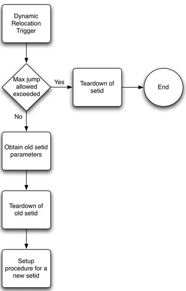
3.3.4. Dynamic Relocation procedure 51
4. Performance analysis
56
4.1. Chain
56
4.1.1. First Scenario : High ED Range 57
4.1.2. Second Scenario : Reduced ED Range 60
4.1.3. Third scenario : Dynamic Relocation 62
4.1.4. Fourth scenario : Slot Selection Algorithms 64
4.1.5. Fifth scenario : Two macro-flows. 65
4.2. Grid
68
4.2.1. First scenario : Three macro-flows. 69
4.2.1. Second scenario : Five macro-flows. 73
4.2.1. Third scenario : Two macro-flows. 75
4.3. Grid with APs
77
4.3.1. First scenario : No Call Admission Control. 78
4.3.2. Second scenario : Call Admission Control. 85
4.3.3. Third scenario : Tolerance set to 1. 89
4.3.4. Fourth scenario : Protocol-model. 90
1. Introduction
Wireless Mesh Networks (WMNs) have emerged as a key technology for next-generation wireless networking. Because of their advantages over other wireless networks, WMNs are undergoing rapid progress and inspiring numerous applications.
Wireless mesh networks (WMNs) are dynamically self-organized and self-configured, with the nodes in the network automatically establishing an ad hoc network and maintaining the mesh connectivity. WMNs are comprised of two types of nodes: mesh routers and mesh clients. Other than the routing capability for gateway/bridge functions as in a conventional wireless router, a mesh router contains additional routing functions to support mesh networking [1]. Through multi-hop communications, the same coverage can be achieved by a mesh router with much lower transmission power. To further improve the flexibility of mesh networking, a mesh router is usually equipped with multiple wireless interfaces built on either the same or different wireless access technologies. In spite of all these differences, mesh and conventional wireless routers are usually built based on a similar hardware platform. Mesh routers have minimal mobility and form the mesh backbone for mesh clients.
Access Point Wireless Bridge Wired Network Client Client Mesh Point
Mesh Point Mesh Point
Mesh Point
In addition to mesh networking among mesh routers and mesh clients, the gateway/ bridge functionalities in mesh routers enable the integration of WMNs with various other networks. Conventional nodes equipped with wireless network interface cards (NICs) can connect directly to WMNs through wireless mesh routers. Customers without wireless NICs can access WMNs by connecting to wireless mesh routers through, for example, Ethernet. Thus, WMNs will greatly help users to be always-on-line anywhere, anytime. Consequently, instead of being another type of ad-hoc networking, WMNs diversify the capabilities of ad-hoc networks. This feature brings many advantages to WMNs, such as low up-front cost, easy network maintenance, robustness, reliable service coverage, etc. Therefore, in addition to being widely accepted in the traditional application sectors of ad hoc networks, WMNs are undergoing rapid commercialization in many other application scenarios such as broadband home networking, community networking, building automation, high-speed metropolitan area networks, and enterprise networking products.
Researchers have started to revisit the protocol design of existing wireless networks, especially of IEEE 802.11 networks, ad hoc networks, and wireless sensor networks, from the perspective of wireless mesh networking. Industrial standards groups, such as IEEE 802.11, IEEE 802.15, and IEEE 802.16, are all actively working on new specifications for WMNs.
The 802.11 working group in IEEE has recently started working on mesh networks in the task group identified as TGs, which will produce the 802.11s standard for mesh networks [2]. The main target of TGs is to investigate and design mesh networks consisting of different WLAN devices performing routing at link layer. TGs is currently working on the presentation and selection of different proposals.
The standard is aimed for approval in 2008. Specifically, 802.11 TGs defines an extended service set (ESS) mesh as a collection of WLAN devices interconnected with wireless links that enable automatic topology learning and dynamic path configuration. 802.11 mesh networks will be based on extensions to the IEEE 802.11 MAC standard, based on the definition of a mesh network architecture and new protocol mechanisms. The architecture will provide an IEEE 802.11 Wireless Distribution System (DS) that supports both broadcast/multicast and unicast delivery at the MAC layer using radio-aware metrics over self-configuring multi-hop
In this work we start by analyzing 802.11s standard and then we focus on one of its optional MAC enhancements, which is Mesh Deterministic Access. Mesh Deterministic Access (MDA) is an access method that allows MPs to access the channel at selected times (called MDAOPs) with lower contention than would otherwise be possible.
We also propose a new mechanism to improve MDA, which is called Dynamic Relocation.
We finally implement MDA and Dynamic Relocation in ns2 network simulator, where is already present the IEEE 802.11 stack and evaluate performance via a simulation analysis.
2. MAC Protocol
This section describes the IEEE 802.11 MAC protocol and the enhancements proposed in the IEEE 802.11s draft.
2.1. 802.11
The IEEE 802.11 includes two access mechanisms: the Distributed Coordination Function (DCF) and the Point Coordination Function (PCF).
ISO/IEC 8802-11: 1999(E)
ANSI/IEEE Std 802.11, 1999 Edition LOCAL AND METROPOLITAN AREA NETWORKS: WIRELESS LAN
9. MAC sublayer functional description
The MAC functional description is presented in this clause. The architecture of the MAC sublayer, including the distributed coordination function (DCF), the point coordination function (PCF), and their coexistence in an IEEE 802.11 LAN are introduced in 9.1. These functions are expanded on in 9.2 and 9.3, and a complete func-tional description of each is provided. Fragmentation and defragmentation are covered in 9.4 and 9.5. Multirate support is addressed in 9.6. The allowable frame exchange sequences are listed in 9.7. Finally, a number of additional restrictions to limit the cases in which MSDUs are reordered or discarded are described in 9.8.
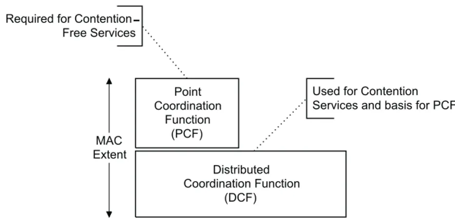
9.1 MAC architecture
The MAC architecture can be described as shown in Figure 47 as providing the PCF through the services of the DCF.
9.1.1 Distributed coordination function (DCF)
The fundamental access method of the IEEE 802.11 MAC is a DCF known as carrier sense multiple access
with collision avoidance (CSMA/CA). The DCF shall be implemented in all STAs, for use within both IBSS
and infrastructure network configurations.
For a STA to transmit, it shall sense the medium to determine if another STA is transmitting. If the medium is not determined to be busy (see 9.2.1), the transmission may proceed. The CSMA/CA distributed algorithm mandates that a gap of a minimum specified duration exist between contiguous frame sequences. A transmit-ting STA shall ensure that the medium is idle for this required duration before attemptransmit-ting to transmit. If the medium is determined to be busy, the STA shall defer until the end of the current transmission. After defer-ral, or prior to attempting to transmit again immediately after a successful transmission, the STA shall select a random backoff interval and shall decrement the backoff interval counter while the medium is idle. A refinement of the method may be used under various circumstances to further minimize collisions—here the transmitting and receiving STA exchange short control frames [request to send (RTS) and clear to send (CTS)frames] after determining that the medium is idle and after any deferrals or backoffs, prior to data transmission. The details of CSMA/CA, deferrals, and backoffs are described in 9.2. RTS/CTS exchanges are also presented in 9.2.
9.1.2 Point coordination function (PCF)
The IEEE 802.11 MAC may also incorporate an optional access method called a PCF, which is only usable
Figure 47—MAC architecture
Figure 2.1 : 802.11 Mac Architecture
The DCF uses a CSMA/CA access scheme : for a station (STA) to transmit, it shall sense the medium to determine if another STA is transmitting; if the medium is idle, then the transmission may proceed; if the medium is busy, then the STA shall defer until the end of the current transmission. The STA performs a backoff procedure after deferral in order to minimize collisions; the backoff procedure starts after the medium has been sensed idle for a DCF Interframe Space (DIFS). When a unicast frame is correctly received by an STA, the latter transmits an acknowledgment frame after a Short Interframe Space (SIFS), which is shorter than DIFS in order to prevent deferring stations from interrupting ongoing frame exchange sequences.
ISO/IEC 8802-11: 1999(E)
ANSI/IEEE Std 802.11, 1999 Edition LOCAL AND METROPOLITAN AREA NETWORKS: WIRELESS LAN
74 Copyright © 1999 IEEE. All rights reserved.
9.2.3 Interframe space (IFS)
The time interval between frames is called the IFS. A STA shall determine that the medium is idle through the use of the carrier-sense function for the interval specified. Four different IFSs are defined to provide pri-ority levels for access to the wireless media; they are listed in order, from the shortest to the longest. Figure 49 shows some of these relationships.
a) SIFS short interframe space
b) PIFS PCF interframe space
c) DIFS DCF interframe space
d) EIFS extended interframe space
The different IFSs shall be independent of the STA bit rate. The IFS timings shall be defined as time gaps on the medium, and shall be fixed for each PHY (even in multirate-capable PHYs). The IFS values are deter-mined from attributes specified by the PHY.
9.2.3.1 Short IFS (SIFS)
The SIFS shall be used for an ACK frame, a CTS frame, the second or subsequent MPDU of a fragment burst, and by a STA responding to any polling by the PCF. It may also be used by a PC for any types of frames during the CFP (see 9.3). The SIFS is the time from the end of the last symbol of the previous frame to the beginning of the first symbol of the preamble of the subsequent frame as seen at the air interface. The valid cases where the SIFS may or shall be used are listed in the frame exchange sequences in 9.7.
The SIFS timing shall be achieved when the transmission of the subsequent frame is started at the TxSIFS Slot boundary as specified in 9.2.10. An IEEE 802.11 implementation shall not allow the space between frames that are defined to be separated by a SIFS time, as measured on the medium, to vary from the nomi-nal SIFS value by more than ±10% of aSlotTime for the PHY in use.
SIFS is the shortest of the interframe spaces. SIFS shall be used when STAs have seized the medium and need to keep it for the duration of the frame exchange sequence to be performed. Using the smallest gap between transmissions within the frame exchange sequence prevents other STAs, which are required to wait for the medium to be idle for a longer gap, from attempting to use the medium, thus giving priority to com-pletion of the frame exchange sequence in progress.
9.2.3.2 PCF IFS (PIFS)
The PIFS shall be used only by STAs operating under the PCF to gain priority access to the medium at the start of the CFP. A STA using the PCF shall be allowed to transmit contention-free traffic after its carrier-sense mechanism (see 9.2.1) determines that the medium is idle at the TxPIFS slot boundary as defined in 9.2.10. Subclause 9.3 describes the use of the PIFS by STAs operating under the PCF.
Figure 49—Some IFS relationships
Figure 2.2 : DCF Inter Frame Spaces
If the Point Coordination Function is used, then the AP alternates a Contention-Free Period (CFP) with a Contention Period (CP). During the CP, the above DCF transfer rules apply. During the CFP the AP polls the stations that are in the CF poll list, using an implementation-dependent algorithm. When polled, a station transmits an MSDU. The AP may also use the CFP to transmit frames addressed to associated stations. The first frame of the CFP is transmitted by the AP at regular intervals (Target Beacon Transmission Time, TBTT) after the medium has been sensed idle for a duration greater than a PCF Inter-Frame Space (PIFS), which is chosen such that SIFS < PIFS < DIFS.
ISO/IEC 8802-11: 1999(E) MEDIUM ACCESS CONTROL (MAC) AND PHYSICAL (PHY) SPECIFICATIONS ANSI/IEEE Std 802.11, 1999 Edition
STAs receiving Data type frames shall only consider the frame body as the basis of a possible indication to LLC, if the frame is of subtype Data, Data+CF-Ack, Data+CF-Poll, or Data+CF-Ack+CF-Poll. CF-Pollable STAs shall interpret all subtype bits of received Data type frames for CF purposes, but shall only inspect the frame body if the frame is of subtype Data, Data+CF-Ack, Data+CF-Poll, or Data+CF-Ack+CF-Poll.
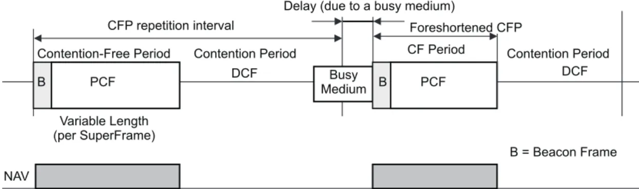
9.3.1 CFP structure and timing
The PCF controls frame transfers during a CFP. The CFP shall alternate with a CP, when the DCF controls frame transfers, as shown in Figure 59. Each CFP shall begin with a Beacon frame that contains a DTIM ele-ment (hereafter referred to as a “DTIM”). The CFPs shall occur at a defined repetition rate, which shall be synchronized with the beacon interval as specified in the following paragraphs.
The PC generates CFPs at the contention-free repetition rate (CFPRate), which is defined as a number of DTIM intervals. The PC shall determine the CFPRate (depicted as a repetition interval in the illustrations in Figure 59 and Figure 60) to use from the CFPRate parameter in the CF Parameter Set. This value, in units of DTIM intervals, shall be communicated to other STAs in the BSS in the CFPPeriod field of the CF Parame-ter Set element of Beacon frames. The CF ParameParame-ter Set element shall only be present in Beacon and Probe Response frames transmitted by STAs containing an active PC.
The length of the CFP is controlled by the PC, with maximum duration specified by the value of the CFP-MaxDuration Parameter in the CF Parameter Set at the PC. Neither the maximum duration nor the actual duration (signaled by transmission of a Control frame of subtype CF-End or CF-End+ACK by the PC) is
Figure 59—CFP/CP alternation
Figure 60—Beacons and CFPs
Figure 2.3 : CFP/CP alternation
Even though it has been shown that the PCF performs better than the DCF with real-time traffic , it is nevertheless unable to guarantee that associated stations will have a parameterized QoS. The reasons behind this failure are: (i) the lack of knowledge at the AP of the traffic specifications and requirements; (ii) no mechanism to determine if a station actually has data to send, which leads to a high polling overhead; (iii) the
interval between two CFPs is too large and the duration of the CFP is limited; (iv) the TBTT may be delayed due to stations unaware of the PCF procedure; and, finally, (v) no admission control can be performed at the AP.
2.2. 802.11s
The IEEE 802.11s extended service set (ESS) mesh aims at applying multi-hop mesh techniques to specify a WDS that can be used to build a wireless infrastructure for small-to-large-scale WLANs. Hence, the ESS or WLAN mesh can be considered as an IEEE 802.11-based WDS, a subset of the DS that consists of a set of devices interconnected with each other via wireless links, resulting in a ‘mesh of connectivity.’ The activities of 802.11s TG comprise the specification of a new protocol suite for the installation, configuration, and operation of WLAN mesh [3]. Its implementation shall be atop the existing PHY layer of IEEE 802.11a/b/g/n operating in the unlicensed spectrum of 2.4- and 5-GHz frequency bands. The specification shall include the extensions in topology formation to make the WLAN mesh self-configure as soon as the devices are powered up. A path selection protocol will be specified in the MAC layer instead of network layer for routing data in the multi-hop mesh topology. This standard is expected to support MAC-layer broadcast and multicast in addition to the unicast transmissions. This standard shall also accommodate devices that are able to support multichannel operations, or are equipped with multiple radios, with an aim to boost the capacity of the overall network. The specification is expected to be adopted as part of the working group standard by March 2008.
MAP MPP Wired Network Client Client MP MP MP MP IEEE 802.11s logical link
Figure 2.4 : Example of 802.11s Mesh Network Architecture
The minimal MP operations include neighbor discovery, channel selection, and forming an association with neighbors. Besides, MPs can directly communicate with their neighbors and forward traffic on behalf of other MPs via bidirectional wireless mesh links. A set of MPs and the mesh links form a WDS, which distinguishes itself from the BSS as defined in the legacy IEEE 802.11. The proposed WLAN mesh also defines a mesh access point (MAP), which is a specific MP but acts as an AP as well. The MAP may operate as a part of the WLAN mesh or in one of the legacy 802.11 modes.
A mesh portal (MPP) is yet another type of MP through which multiple WLAN meshes can be interconnected to construct networks of mesh networks. An MPP can also co-locate with an IEEE 802.11 portal and function as a bridge/gateway between the WLAN mesh and other networks in the DS. To uniquely identify a WLAN mesh, a common mesh ID is assigned to each MP, similar to the use of service set identifier (SSID) to represent an ESS in legacy 802.11 networks.
The major components of the proposed 802.11s Mesh Coordination Function (MCF) are shown in figure.
IEEE Wireless Communications • April 2006 59 mesh ID is assigned to each MP, similar to the
use of service set identifier (SSID) to represent an ESS in legacy 802.11 networks.
THEMEDIUMACCESSCOORDINATIONFUNCTION
The major components of the proposed 802.11s MCF are shown in Fig. 3. Built on top of the legacy physical layer specification, 802.11s shall explicitly provide the WLAN mesh services. These include topology learning, routing and forwarding, medium access coordination, mesh configuration and management, topology discov-ery and association, mesh measurement, inter-working, and security functions [5].
For interworking of the WLAN mesh with other networks, the IEEE 802.1D standard shall be incorporated in the mesh portals (MPPs), which define the interworking framework and service access interface across all 802 standards. Similarly, security architecture shall be based on the IEEE 802.11i standard, which specifies secu-rity features for all WLAN networks. In the fol-lowing subsections, we describe only the major services and functions germane to the mesh capability.
Mesh Topology Learning, Routing, and Forwarding —
This service set focuses on the peer-to-peer dis-covery of MPs. It enables automatic topology learning, establishes links, and eventually forms a dynamic data delivery path across the WLAN mesh.
Topology discovery and formation: A new node (a candidate MP) initially gathers informa-tion from neighboring MPs that belong to the active WLAN mesh, by either the active scan-ning (i.e., sending probe messages) or the pas-sive listening (i.e., receiving periodic beacons) mechanism. Based on factors such as peer capa-bility, power saving capacapa-bility, security informa-tion, and link quality, two peers associate with each other, forming a partial or full mesh topol-ogy.
Path selection protocol: The MCF architec-ture provides an extensible framework such that the enhanced routing protocols and metrics tai-lored for particular applications can be imple-mented and used as required. A layer-2 path selection protocol is supposed to handle unicast and broadcast/multicast data delivery in the WLAN mesh. Since the network might have both nonmobile and mobile MPs, a hybrid rout-ing protocol that includes both proactive and on-demand schemes is expected to be more suitable. Therefore, a hybrid scheme of using the ad hoc on-demand distance vector (AODV) and the optimized link state routing (OLSR) protocol is proposed to support wide range of application scenarios [6,7]. In addition, radio-aware metrics that reflects actual link condition are proposed, thereby making the routing protocols more robust against link failures. For example, an air-time metrics [6] reflects the cost of channel, path, and packet error rate. Similarly, another metric named weighted radio and load aware (WRALA) [7] is based on the protocol overhead at the MAC and PHY layers, size of the frame, bit rate, link load, and error rate.
Forwarding scheme: WLAN mesh traffic con-sists of 4-address data frames similar to that of
the 802.11-1999 specification [4], with two new extensions for quality of service (QoS) and mesh control. Upon receiving such frames, the MP checks for its authenticity and its destination MAC address before forwarding. On arrival of the 3-address frame in MAP from the associated STA, the frame shall be converted to the 4-address format and forwarded towards the desti-nation. Similarly, forwarding of multicast and broadcast traffic is also supported if they are 4-address data frames from the known source. The time-to-live subfield present in the data frame is decremented by every forwarding MP for con-trolling the broadcast traffic in the WLAN mesh.
Medium Access Coordination — The medium access
coordination of the proposal [6, 7] is based on the enhanced distributed channel access (EDCA) mechanism used in 802.11e [8]. The proposed MAC mechanisms facilitate congestion control, power saving, synchronization, and bea-con collision avoidance. Using the proposed mechanisms, it shall be possible to enable multi-ple channel operations in multiradio or single radio, as well as mixed, environments. The mul-tichannel MAC proposal is based on the com-mon channel framework (CCF) [9], which is compliant to the legacy channel access mecha-nisms. It is primarily designed for efficient use of link capacity by enabling multichannel opera-tions in nodes that are equipped with a single radio interface.
Mesh Configuration and Management —
Self-configur-ing paths and links offer one of the main advan-tages of mesh networks. Since their deployment can be unmanaged, autonomic management modules are required for their continuous oper-ation. Protocols for association between MPs and the nodes outside the WLAN mesh can minimize the burden of manual configuration for the service provider.
Mesh management ensures the smooth oper-ation of the network. Since any available MP can route packets, a failure of a particular device is not likely to affect the network as a
Figure 3. Architecture for the 802.11s MCF sublayer.
PHYs
Mesh measurement Mesh topology
learning, routing and forwarding Medium access coordination Discovery and association Mesh security 802.11 service
integration Mesh configuration and management Mesh interworking with other 802 networks
KO LAYOUT 4/5/06 12:37 PM Page 59
Figure 2.5 : Components of 802.11s MCF
Built on top of the legacy physical layer specification, 802.11s shall explicitly provide the WLAN mesh services. These include topology learning, routing and forwarding, medium access coordination, mesh configuration and management, topology discovery and association, mesh measurement, interworking, and security functions. For interworking of the WLAN mesh with other networks, the IEEE 802.1D standard shall be incorporated in the mesh portals (MPPs), which define the interworking framework and service access interface across all 802 standards. Similarly, security architecture shall be based on the IEEE 802.11i standard, which specifies security features for all WLAN networks.
2.2.1. MAC frame formats
The MAC frame format comprises a set of fields that occur in a fixed order in all frames. Figure depicts the general MAC frame format.
!"""#$%&'())*+,)(&-.#/012#'&&3 " # $ % & ' ! ( ) "* "" "# "$ "% "& "' "! "( ") #* #" ## #$ #% #& #' #! #( #) $* $" $# $$ $% $& $' $! $( $) %* %" %# %$ %% %& %' %! %( %) &* &" &# &$ &% && &' &! &( &) '* '" '# '$ '% '& !"#$%&'(#)*%'&+, !"-#./0#)%&'(#)*%'&+, !"-"1#2(3(%&4#)%&'(#)*%'&+ !"#$%&'("&'(&)('*$'+,-,.'#$/'0*%12& +3-'#4'4"56$7 +,-./01.2345-.263547.86593:;-;.4.;-7.62.2:-<=;.7,47.688>3.:?.4.2:@-=.63=-3.:?.4<<.2345-;A.B:C>3- !D".=-9:87; 7,-.C-?-34<./01.2345-.263547A.+,-.2:3;7.7,3--.2:-<=;.EB345-.16?736<F.G>347:6?HIGF.4?=.0==3-;;."J.4?=.7,-<4;7. 2:-<=. EB1KJ. :?. B:C>3- !D". 86?;7:7>7-. 7,-. 5:?:54<. 2345-. 263547. 4?=. 43-. 93-;-?7. :?. 4<<. 2345-;. E-@8-97 LGMJF.:?8<>=:?C.3-;-3N-=.7O9-;.4?=.;>P7O9-;A.+,-.2:-<=;.0==3-;;.#F.0==3-;;.$F.K-Q>-?8-.16?736<F.0==3-;; %F.R6K.16?736<F.S+.16?736<F./-;,.S-4=-3F.4?=.B345-.T6=O.43-.93-;-?7.6?<O.:?.8-374:?.2345-.7O9-;.4?=.;>PD 7O9-;A.U,-?.93-;-?7F.7,-./-;,.S-4=-3.2:-<=.:;.93-9-?=-=.76.7,-.B345-.T6=OA.+,-./-;,.S-4=-3.2:-<=.:;.,4?D =<-=.:=-?7:84<<O.76.7,-.86?7-?7;.62.7,-.P6=O.V:7,.3-;9-87.76./MGW.9368-;;:?CA..X48,.2:-<=.:;.=-2:?-=.:?.!A"A$A +,-.263547.62.-48,.62.7,-.:?=:N:=>4<.;>P7O9-;.62.-48,.2345-.7O9-.:;.=-2:?-=.:?.!A#A.+,-.86596?-?7;.62.54?D 4C-5-?7.2345-.P6=:-;.43-.=-2:?-=.:?.!A$A.+,-.263547;.62.54?4C-5-?7.2345-;.62.;>P7O9-.087:6?.43-.=-2:?-= :?.!A%A..+,-.263547.62.54?4C-5-?7.2345-;.62.;>P7O9-./><7:,69.087:6?.:;.=-2:?-=.:?.!A%PA !"#$#%&' ( ( ) ) ) ( ) ( * +,-.// * B345-. 16?736< G>347:6?H. IG 0==3. " 0==3.# 0==3.$ 8-.16?DK-Q>-? 736< 0==3. % 16?736<R6K. 16?736<S+. T6=O B1K /-;,. S-4=-3 I=4#J>B@>7
$567%(#!8-9./0#)%&'(#)*%'&+Figure 2.6 : MAC frame format
The first three fields (Frame Control, Duration/ID, and Address 1) and the last field (FCS) in figure constitute the minimal frame format and are present in all frames, including reserved types and subtypes. The fields Address 2, Address 3, Sequence Control, Address 4, QoS Control, HT Control, Mesh Header, and Frame Body are present only in certain frame types and subtypes. When present, the Mesh Header field is prepended to the Frame Body. The Mesh Header field is handled identically to the contents of the body with respect to MPDU processing.
The mesh header field is a 5 to 23 octet field that includes: • an 8-bit Mesh Flags field to control mesh header processing
• a time to live field for use in multi-hop forwarding to aid in limiting the effect of transitory path selection loops
• a mesh sequence number to suppress duplicates in broadcast/multicast forwarding and for other services
• in some cases a 6, 12, or 18-octet mesh address extension field containing extended addresses enabling up to a total of 6 addresses in mesh frames
The Mesh Header field, shown in figure, is present in Data frames if and only if they are transmitted between peer MPs with an established peer link. Data frames including the Mesh Header field are referred to as Mesh Data frames.
!"""#$%&'())*+,)(&-.#/012#'&&3 " # $ % & ' ( ) ! "* "" "# "$ "% "& "' "( ") "! #* #" ## #$ #% #& #' #( #) #! $* $" $# $$ $% $& $' $( $) $! %* %" %# %$ %% %& %' %( %) %! &* &" &# &$ &% && &' &( &) &! '* '" '# '$ '% '& +,-./012.345/6-708/3452-9/582:/8;/4202<-5;=2>;-2?<37-26080@2A/82/525-82832"2AB2CD52E372/46/F/6G011B20667-55-6 C+HIJCCDHI525-482832024-/K;A37/4K2CD2:;-428;-7-207-2<37-2E70<-52832A-287045</88-628328;082CD2/428;-87045</[email protected]/48-7F01=2>;-2?<37-26080@2A/82/525-82832"2AB2CD52E372K73G,20667-55-62C+HI5J CCDHI52:;-428;-7-207-2<37-2K73G,20667-55-62E70<-52832A-287045</88-62/428;-287045</[email protected] /48-7F01= !"#$%&'&($')*++*,-".'"$,'/+01#$'0)&$%'23435367 !"#"$"%&'()*+',)&-).'/0)1-!"#"$"%&"#'2)3).&1 >;-2<-5;2;-06-72E/-162/5202&832#$23.8-82E/-1628;082/4.1G6-5L M 042)NA/82C-5;2O10K52E/-162832.3487312<-5;2;-06-72,73.-55/4K2
M 028/<-28321/F-2E/-162 E372G5-2/42<G18/N;3,2E37:076/4K2 8320/62/421/</8/4K2 8;-2-EE-.823E2 87045/837B2,08; 5-1-.8/342133,5 M 02<-5;25-PG-4.-24G<A-728325G,,7-5526G,1/.08-52/42A7306.058J<G18/.0582E37:076/4K20462E37238;-725-7N F/.-5 M 0462/4253<-2.05-5202'Q2"#Q2372")N3.8-82<-5;20667-552-98-45/342E/-162.3480/4/4K2-98-46-620667-55-5 -40A1/4K2G,2832028380123E2'20667-55-52/42<-5;2E70<-52 >;-2C-5;2R-06-72E/-16Q25;3:42/42O/KG7- 5%Q2/52,7-5-482/42H0802E70<-52/E20462341B2/E28;-B207-287045</88-6 A-8:--42,--72CD52:/8;2042-580A1/5;-62,--721/4S=2H0802E70<-52/4.1G6/4K28;-2C-5;2R-06-72E/-16207-27-E-77-6283 052 C-5;2 H0802 E70<-5=2 >;-2 C-5;2 R-06-72 /52 01532 /4.1G6-62 /42 C040K-<-482 E70<-52 3E2 5GA8B,-2 CG18/;3, T.8/34=2 !"#"$"%&"4'()*+'51&6*'/0)1->;-2C-5;2O10K52E/-16Q25;3:42/42O/KG7- 5&Q2/52)2A/852/421-4K8;204628;-2E10K528;-7-/4207-2G5-62832.3487312<-5;N 5,-./E/.2;-06-72,73.-55/4KQ2-=K=Q2E372<-5;20667-552-98-45/34= >;-2T667-552U98-45/342VTUW2C36-2E/-162/52G5-62832/46/.08-28;-2.348-48523E28;-2C-5;2T667-552U98-45/34 E/-16=22>0A1- 5#26-E/4-52F01/62F01G-52E3728;-2T667-552U98-45/342C36-204626-5.7/A-528;-2.377-5,346/4K2.34N !"#$#%&'( ( ) *+',+'(-+'./'(0 C-5;2O10K5 C-5;2>/<-2>32X/F-2 V>>XW C-5;2+-PG-4.-2YG<A-7 C-5;2T667-552U98-45/342 V,7-5-482/4253<-2.34N E/KG708/345W 5067.)'*89()*+',)&-).'/0)1-Z* 2 2Z" Z# 2 2Z( T667-552U98-45/342VTUW2C36- [-5-7F-6 Z/85L2# '
5067.)'*%9()*+'51&6*'/0)1-Figure 2.7 : Mesh Header Field
The Frame Body is a variable length field that contains information specific to individual frame types and subtypes.
2.2.2. Management frame
Management frames are exchanged between neighboring Mesh Points in order to solve important tasks, like beaconing and association. The frame format for a management frame is defined in figure.
!"""#$%&'())*+,)(&-.#/012#'&&3 ! " # $ % & ' ( ) !* !! !" !# !$ !% !& !' !( !) "* "! "" "# "$ "% "& "' "( ") #* #! #" ## #$ #% #& #' #( #) $* $! $" $# $$ $% $& $' $( $) %* %! %" %# %$ %% %& %' %( %) &* &! &" &# &$ &% +,+-,./0012034,02.5+,0367,0890:,5;<=>0<34,.05??.,990+53;[email protected],90577B6>059097,;828,?08=0!!/!/"/#/0C.5+,90<2 367,0D.<-,0E,FA,930G834050@.<A705??.,9908=034,0H??.,990!028,B?05.,07.<;,99,?0590?,9;.8-,?08=0!!/!/#/"/!/ I4,0 5??.,990 28,B?90 2<.0 5BB0 +5=5@,+,=30 2.5+,90 ?<0 =<30 J5.60 -60 2.5+,0 9A-367,0 9A-367,90 ,K;,730 LAB384<7 H;38<=05.,05902<BB<G9/ I4,0H??.,990#0M:NN1OP028,B?0<2034,0+5=5@,+,=302.5+,0890?,3,.+8=,?05902<BB<G9Q 5P 12034,0NIH08905=0HD0<.0890599<;853,?0G83405=0HD>034,0:NN1O089034,05??.,990;A..,=3B608=0A9,0-6034, NIH0;<=358=,?08=034,0HD/ -P 12034,0NIH089050+,+-,.0<205=01:NN>034,0:NN1O089034,0:NN1O0<2034,01:NN/ ;P 1=0+5=5@,+,=302.5+,90<209A-367,0D.<-,0E,FA,93>034,0:NN1O0890,834,.05097,;828;0:NN1O>0<.034,0G8B?R ;5.?0:NN1O0590?,28=,?08=034,07.<;,?A.,9097,;828,?08=0!!/!/#/ ?P C<.098=@B,R4<70+5=5@,+,=302.5+,903.5=9+833,?0-60LD9>034,0:NN1O028,B?0890=<30A9,?05=?094<AB?0-, 9,303<0*/ I4,0H??.,990!0MEHSOHP028,B?089034,0?,938=538<=0<2034,02.5+,/ I4,0H??.,990"0MIHSNHP028,B?089034,05??.,990<2034,0NIH03.5=9+8338=@034,02.5+,/ I4,05??.,99028,B?902<.034,0+5=5@,+,=302.5+,09A-367,0LAB384<70H;38<=05.,05902<BB<G9/ I4,0H??.,990!0MEHP028,B?089034,0.,;,8J,.0<2034,02.5+,/ I4,0H??.,990"0MIHP028,B?089034,03.5=9+833,.0<2034,02.5+,/ I4,0H??.,990#0MOHP028,B?089034,0?,938=538<=0<2034,02.5+,/
T;3,39Q0" " & & & " *R"#!" $ C.5+,
U<=3.<B OA.538<=V1O H??.,99!0MOHP H??.,99"0MNHP H??.,99#0 :NN1O
N,FA,=;,
U<=3.<B :<?6 CUN
I=4#J>B@>7
!"#$%&'()*+,-./.#&0&/1'2%.0&'23%0.1
Figure 2.8 : Management Frame Format
The body of a management frame contains Information Elements, depending on the subtype. A partial list of IEs is contained in the following table :
Information Element Length
Mesh Configuration 17
Mesh ID 2 to 34
Link Metric Report 3 to 257
Congestion Notification 10
Peer Link Management 5 to 9
Mesh Channel Switch Announcement
15
Mesh Neighbor List 4 to 257
Beacon Timing 7 to 257
MDAOP Setup Request 7
MDAOP Setup Reply 4 to 257
MDAOP Advertisements 3 to 257
MDAOP Set Teardown 9
Information Element Length
Path Request 39 to 257
Path Reply 34 to 257
Path Error 14
List of Information Elements
Specific management frame types are : • Beacon frame
• Probe Request frame • Probe Response frame • Multihop Action frame
Other types of Management frame formats, called Action frames, are distinguished by a category and action field inside Management body field.
Categories currently defined are : • Mesh Peer Link Management • Mesh Link Metric
• Mesh Path Selection • Mesh Interworking
• Mesh Resource Coordination
Frames inside categories are differentiated by Action Field.
Mesh Peer Link Management category includes :
• Peer Link Open frame • Peer Link Confirm frame • Peer Link Close frame
The Peer Link Open frame is used to open a peer link. Peer Link Confirm frame is used by neighbor to confirm a peer link. Peer Link Close frame is used to close a peer link.
Mesh Link Metric category includes :
• Link Metric Request • Link Metric Report
The Link Metric Request frame is transmitted by an MP to a peer MP in a mesh to request metric information. The Link Metric Report frame is transmitted by an MP to a peer MP in a mesh to advertise metric information.
Mesh Path Selection category includes :
• Path Request • Path Reply • Path Error
• Root Announcement • RA-OLSR
The Path Request frame is transmitted by a source MP to discover the path to the destination MP using the HWMP protocol. The Path Reply frame is transmitted by a destination MP to a source MP in the mesh to determine the path between the source and destination MP. The Path Error frame is transmitted by an MP that detected a link error on a mesh path to the precursor MP(s). The Root Announcement frame is advertised by a Root MP. These frames may be transmitted using group addresses or individual addresses.
The RA-OLSR frame is transmitted, instead, by MPs using the RA-OLSR path selection protocol.
Mesh Interworking category includes :
• Portal Announcement
The Portal Announcement is transmitted by an MPP to announce its presence in the mesh network. This frame is transmitted using group addresses.
Mesh Resource Coordination category includes :
• Congestion Control Notification • MDA Setup Request
• MDA Setup Reply
• MDAOP Advertisement Request • MDAOP Advertisements
• MDAOP Set Teardown • Beacon Timing Request • Beacon Timing Response
• Mesh Channel Switch Announcement • Connectivity Report
The Congestion Control Notification frame is sent by an MP to its peer MP(s) to indicate its congestion status.
The Mesh Deterministic Access MDA Setup Request frame is used to request the setup of a set of MDAOPs. It is transmitted by an active MP to a peer MDA-active MP. The Mesh Deterministic Access MDA Setup Reply frame is used to reply to an MDAOP Setup Request. The MDAOP Advertisement Request frame is transmitted by an MDA-active MP to request MDA advertisements from neighbors. The Mesh Deterministic Access MDAOP Advertisements frame is transmitted by an MDA-active MP to one or more peer MDA-active MPs. This frame may be transmitted using group addresses or individual addresses. The Mesh Deterministic Access MDAOP Set Teardown frame is transmitted by an MDA-active MP to one or more peer MDA-active MPs.
The Beacon Timing Request frame is used to request beacon timing information from peer MPs. This frame is transmitted using group addresses or individual addresses. The Beacon Timing Response frame is used to respond to a Beacon Timing Request frame with neighbor MP beacon timing information.
The Mesh Channel Switch Announcement frame is transmitted by an MP to signal a channel switch.
The Connectivity Report frame is transmitted by an MP to advertise the number of beacon broadcasters during the reporting interval and the peers that transmitted a connectivity report and the Power Management Mode of each peer.
2.2.3. Mesh networking procedures.
Mesh discovery procedures require that MPs have sufficient informations about
themselves and potential neighbors. This process requires detection of potential mesh neighbors through Beacons or through active scanning using Probe Requests.
MP1 MP2
Beacon
Beacon
Neighbors have been Discovered
Figure 2.9 : Neighbor Discovery through beacons
An MP shall support at least one mesh profile. A mesh profile consists of: 1. A Mesh ID
2. A path selection protocol identifier 3. A path selection metric identifier
The purpose of discovery procedure is to discover candidate peer MPs and their properties, covering cases both before and after an MP is a member of a mesh network.
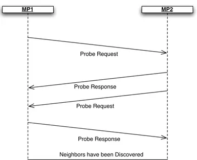
A configured MP, by definition, has at least one mesh profile. If the MP is a member of a mesh, exactly one mesh profile is active. An MP performs passive or active scanning to discover neighbor MPs.
MP1 MP2
Probe Request
Probe Response
Probe Request
Probe Response Neighbors have been Discovered
Figure 2.10 : Neighbor Discovery through active scanning
The MP attempts to discover all neighbor and candidate peer MPs, and maintains the neighbor MP information in Neighbor Table indicating the MAC address of each MP, the most recently observed link state parameters, the received channel number and state.
If an MP is unable to detect neighbor MPs, it may adopt a Mesh ID from one of its mesh profiles, and proceed to the active state. This may occur, for example, when the MP is the first MP to power on (or multiple MPs power on simultaneously). Peer MP links are established later as part of the continuous mesh peer link management procedures.
The Mesh Peer Link Management protocol is used to establish and close peer links between MPs. MPs shall not transmit data frames or management frames other than the ones used for discovery and peer link management until the peer link has been established. An MP shall be able to establish at least one mesh link with a peer MP, and may be able to establish many such links simultaneously, if the maximum number of peer MPs is not reached.
MP1 MP2
Peer Link Open
Peer Link Confirm MP1 is Associated
Figure 2.11 : Peer Link Setup at MP1
A Peer Link Open frame requests that a mesh link instance be established between the Peer Link Open sender and the receiver. The MP shall send a Peer Link Confirm frame in response to the Peer Link Open frame if the link instance proceeds with the protocol. The Peer Link Close frame is used to inform the receiver to close the mesh peer link. The protocol succeeds in establishing a mesh link when the following requirements are satisfied:
1. both MPs have sent and received (and correctly processed) a Peer Link Open frame regarding this mesh link
2. both MPs have sent and received (and correctly processed) a corresponding Peer Link Confirm frame regarding this mesh link.
An MP PHY shall perform Network Channel Selection Procedure in a controlled way such that it enables the formation of a mesh network that coalesces to a unified channel for communication. The MP PHY shall establish links with neighbors that match the Mesh ID and Mesh Profile and select its channel.
An MP PHY shall periodically perform passive or active scanning to discover neighboring MPs. If an MP is unable to detect neighbor MPs, it may adopt a Mesh ID from one of its profiles, select a channel for operation, and select an initial channel precedence value. The initial channel precedence value shall be initialized to a random value. In the event that an MP’s PHY discovers a disjoint mesh, that is, the list of candidate peer MPs spans more than one channel, the MP shall select the channel that is indicated by the candidate peer MP that has the numerically highest channel precedence indicator to be the unification channel.
802.11s standard includes an extensible framework to enable flexible implementation of Path Selection Protocols and Metrics within the mesh framework. The standard includes a default mandatory path selection protocol (HWMP) and default mandatory path selection metric (Airtime Link Metric) for all implementations, to ensure minimum capabilities for interoperability between devices from different vendors. However, the standard also allows any vendor to implement any path selection protocol and/or path selection metric in the mesh framework to meet special application needs, for instance with high mobility of MPs. The mesh framework allows flexibility to integrate future path selection protocols for wireless mesh networks.
An MP may include multiple protocol implementations as well as multiple metric implementations, but only one path selection protocol and only one path selection metric shall be active in a particular mesh at a time.
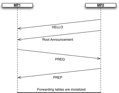
The Hybrid Wireless Mesh Protocol (HWMP) is a mesh path selection protocol that combines the flexibility of on-demand path selection with proactive topology tree extensions. The combination of reactive and proactive elements of HWMP enables optimal and efficient path selection in a wide variety of mesh networks.
MP1 MP2
HELLO
Root Announcement
PREQ
PREP
Forwarding tables are inizialized
Figure 2.12 : Path Selection
HWMP supports two modes of operation depending on the configuration. These modes are:
• On demand mode: this mode allows MPs to communicate using peer-to-peer paths. The mode is used in situations where there is no root MP configured. It is also used in certain circumstances if there is a root MP configured and an on demand path can provide a better path to a given destination in the mesh.
• Proactive tree building mode
On demand and proactive modes may be used concurrently.
It is optional for an MP to support synchronization. An MP supporting synchronization may choose to be either synchronizing or non-synchronizing based on either its own requirements or the requirements of its peer MPs.
A synchronizing MP is an MP that updates its TSF timer based on the time stamps and offsets received in Beacon frames and Probe Response frames from other synchronizing MPs. Synchronizing MPs should attempt to maintain a common TSF time called the Mesh TSF time. All Beacon frames and Probe Response frames by synchronizing MAPs carry informations to advertise its self offset value relative to the Mesh TSF time. Synchronizing MPs translate the received time stamps and offsets from Beacon frames and Probe Response frames from other synchronizing MPs to their own timer base.
3. Mesh Deterministic Access
In this section we describe an optional Mesh networking procedure called MDA. We start with the version that appears in the 802.11s draft, then we show how we implemented that in network simulator (ns-2). Finally, we propose a new mechanism to improve MDA, which is called Dynamic Relocation.
3.1. MDA Standard
Mesh Deterministic Access (MDA) is an optional access method that allows MPs to access the channel at selected times with lower contention than would otherwise be possible. MDA sets up time periods (MDAOPs) in mesh neighborhoods when a number of MDA-supporting MPs that may potentially interfere with each others’ transmissions or receptions are set to not initiate transmission sequences. For each such time period, supporting MPs that set up the state for the use of these time periods are allowed to access the channel using MDA access parameters (CWMin, CWMax, and AIFSN). In order to use the MDA method for access, an MP shall be a synchronizing MP.
An MDAOP is a period of time within every Mesh DTIM interval that is set up between the MDAOP owner and the addressed MP. Once an MDAOP is setup :
• The MDAOP owner uses CSMA/CA and backoff to obtain a TXOP and using parameters MDACWmin, MDACWmax, and MDAIFSN. The ranges of values allowed for MDACWMin, MDACWMax, and MDAIFSN parameters are identical to those allowed for EDCA.
• The MDAOP is advertised by both the MDAOP owner and the addressed MP. All MDA supporting MPs other than the MDAOP owner shall defer initiating new transmissions during the TXOP initiated in the MDAOP.
November 2006
Slide 64
IEEE 802.11s Tutorial
Mesh Deterministic Access (MDA)
• MAC enhancement based on a reservation protocol
• QoS support in large scale distributed Mesh networks
• Synchronized operation
• Reduced contention (two-hop clearing)
• Distributed scheduling
t !"#"$%"&'()' &"%*+"'A !"#"$%"&'()' &"%*+"'B ,--"&*./"'/$.0#-*##*10'("2*0' 3*/415/'$.0&1-'(.+6177 8199*#*10'&5"'/1' +10/"0/*10'(.#"&' .++"##Figure 3.1 : MDAOPs during DTIM
A set of MDAOPs may be setup for individually addressed transmissions from a transmitter to a receiver by the transmitter. Such a set is identified by a unique ID called the MDAOP Set ID. The MDAOP Set ID has to be unique for a transmitter, so that the MDAOP set ID and the transmitter (or set owner) MAC address uniquely identifies an MDAOP set in the mesh. The MDAOP set ID is a handle that allows operation such as setup and teardown to be conducted together for the entire set of MDAOPs in an MDAOP set.
A TXOP that is obtained by an MP by using MDA parameters in an MDAOP is called an MDA TXOP. An MDA TXOP is required to end within the MDAOP in which it was obtained. Thus, an MDA TXOP ends either by MDA TXOP limit time after it began or by MDAOP end time, whichever is earlier.
In a MP’s mesh neighborhood, all the TX-RX times reported by its neighbors (in their MDAOP advertisements) form a set of MDAOPs that are already being used in the neighborhood. No new MDAOPs may be set up by the MP during these times. These times are referred to as Neighborhood MDAOP times for the MP. In effect, Neighborhood MDAOP Times at an MP include all MDAOPs for which the MP and its neighbors are either the transmitters or receivers.
The Interfering times reported by an MP in its MDAOP advertisements are times that may not be used for a new MDAOP with that specific MP. While the MP itself is not the transmitter or receiver in an MDAOP during these times, one of its neighbors is. New MDAOPs to the MP during these times may experience interference. However, new MDAOPs may be setup with another MP during these interfering times. Thus, for every neighbor, there is a set of times that are interfering. These times are referred to as Neighbor MDAOP interfering times for that neighbor.
The MDA access fraction at an MP is the ratio of the total duration of its ‘Neighborhood MDAOP Times’ in a Mesh DTIM interval to the duration of the Mesh DTIM interval. This parameter may be used to limit the use of MDA in an MP’s mesh neighborhood to a certain fraction of the total channel time. Before attempting to set up an MDAOP Set with a neighbor, an MP is required to ensure that the new MDAOP set does not cause the MAF of its neighbors to exceed their MAF Limit. An MDAOP setup request shall be refused by the intended receiver if the MAF limit of its own neighbors is exceeded due to the new setup.
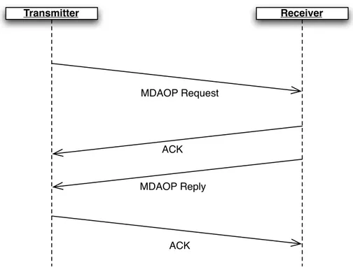
The setup of an MDAOP set is initiated by the intended transmitter, and is accepted/ rejected by the intended receiver. Once accepted, the transmitter is referred to as the owner of the MDAOP. The setup procedure for an MDAOP set is as follows:
I. The MP that intends to be the transmitter in a new MDAOP set builds a map of Neighborhood MDAOP times in the Mesh DTIM interval after hearing Advertisements from all of its neighbors that have MDA active.
II. Based on traffic characteristics, it then chooses MDAOP starting times and durations in the Mesh DTIM interval that do not overlap with either its Neighborhood MDAOP Times or the Neighbor MDAOP Interfering Times of the intended receiver. It also avoids using times that are known to it as being used by itself or one of its neighbors for other activities such as beacon transmissions. III. It then verifies that the new MDAOP Set will not cause the MAF limit to be
crossed for its neighbors. If MAF limit would be crossed for its neighbors, due to the new MDAOP Set, it suspends the setup process.
IV. If the MAF limits at all neighbors are respected despite the new MDAOP set, it transmits an MDAOP Setup request information element to the intended receiver with chosen MDAOP locations and durations.
V. The receiver of the MDAOP Setup Request information element checks to see if the MDAOP times have overlap with its Neighborhood MDAOP Times. The receiver also checks if the new MDAOP Set will cause the MAF limit to be crossed for its neighbors. The MDAOP Setup Reply information element is used to reply to a setup request.
VI. The receiver rejects the setup request if there are overlaps of the requested MDAOP set with its Neighborhood MDAOP Times, or other times that it knows are set to be used by itself or its neighbors for activities such as beacon
transmissions. It may suggest alternate times by including the optional field Alternate Suggested Request information element in the MDAOP Setup Reply element.
VII. The receiver also rejects the setup request if the MAF limit of itself or its neighbors will be exceeded due to the new setup.
VIII. If suitable, the receiver accepts the setup. !"""#$%&'())*+,)(&-.#/012#'&&3
!! 4562789:;#<#'&&3#!"""(#=11#789:;*#7>*>7?>@( A:8*#8*#BC#0CB6675?>@#!"""#D;BC@B7@*#,7BE;.#*0FG>H;#;5#H:BC9>( " # ! $ % & ' ( ) "* "" "# "! "$ "% "& "' "( ") #* #" ## #! #$ #% #& #' #( #) !* !" !# !! !$ !% !& !' !( !) $* $" $# $! $$ $% $& $' $( $) %* %" %# %! %$ %% %& %' %( %) &* &" &# &! &$ &% +,-./01,2+..34-+1-+14+5+460778-044/3,,34-9:;-0<.+=1->/023,?-@A3->=/20.-=>-.A3-+1>=/20.+=1-373231.-+,-0, ,A=B1-+1-C+D6/3 ,#)? @A3-E73231.-F:-+,-,3.-.=-.A3-50763-D+531-+1-@0G73 'H#&->=/-.A+,-+1>=/[email protected]+,-,3.-.=-% =<.3.,? @A3-9:;IJ-K3.-F:->+374-+,-01-3+DA.-G+.-61,+D134-162G3/-.A0.-/3L/3,31.,-.A3-F:->=/-.A3-/3M63,.34-K3.?-F.-+, 43.3/2+134-G8-.A3-9:;IJ-K3.-=B13/?-NA31-6,34-+1-<=2G+10.+=1-B+.A-.A3-9;O-044/3,,-=>-.A3-9:;IJ ,3.-=B13/P-.A3-9:;IJ-K3.-F:-61+M6378-+431.+>+3,-.A3-9:;IJ-K3.?-@A3-9:;IJ-:6/0.+=1->+374-,L3<+>+3,-.A3-46/0.+=1-=>-.A3-9:;IJ-+1-267.+L73,-=>-!# ? @A3-9:;IJ-J3/+=4+<+.8->+374-+,-0-1=1H13D0.+53-+1.3D3/-.A0.-,L3<+>+3,-.A3-162G3/-=>-,6G+1.3/507-L3/+=4,-G8 BA+<A- .A3- 93,A- :@F9- +1.3/507- +,- 4+5+434?- ;- 50763- =>- Q3/=- +14+<0.3,- 0- 1=1H/3L30.34- /3,3/50.+=1- >=/- 014 9:;IJ-+1-.A3-23,A-:@F9-+1.3/507->=77=B+1D-.A3-,3.6L? @A3-9:;IJ-I>>,3.->+374-,L3<+>+3,-.A3-L=,+.+=1-=>-01-9:;IJ-G3D+11+1D->/=2-.A3-G3D+11+1D-=>-.A3-93,A :@F9-+1.3/507-014-,6G,3M631.-,6G+1.3/507-L3/+=4,-B+.A+1-.A3-93,A-:@F9-+1.3/507?-@A3-50763-+,-,L3<+>+34-+1 267.+L73,-=>-!# ? ;1- 3R02L73- =>- L3/+=4+<+.8P- 46/0.+=1P- 014- =>>,3.- 50763,- >=/- 0- L3/+=4+<- 9:;IJ- F1>=- >+374- +,- ,A=B1- +1 C+D6/3 ,!*?--F1-.A+,-L0/.+<670/-3R02L73P-.A3-L3/+=4+<+.8-3M607,->=6/P-,=-.A0.-.A3/3-0/3->=6/-,6G+1.3/507,-B+.A+1 .A3-23,A-:@F9-+1.3/507?-;,->6/.A3/-+776,./0.34-+1-.A3->+D6/3P-.A3-.B=-=>>,3.-50763,-+14+<0.3-.A3-,.0/.-=>-.A3 9:;IJ-/370.+53-.=-.A3-,.0/.-=>-.A3,3-,6G+1.3/507,? !"#$%&'()*+,-.$&('/0%'1&%"02"3'45671'89/0'/"&.2'/0%'-9'&:-;<.&'45671'(&= >?)?@?AB'45671'C&=$<'D&<.E'&.&;&9= @A3-9:;IJ-K3.6L-S3L78-373231.-+,-6,34-.=-/3L78-.=-01-9:;IJ-K3.6L-S3M63,.?-F.,->=/20.-+,-0,-,A=B1-+1 C+D6/3 ,!"[email protected]:-+,-,3.-.=-.A3-50763-D+531-+1-@0G73 'H#&->=/-.A+,-+1>=/[email protected] +,-,3.-.=-!? I<.3.,T-" " " " " # E73231.-F: U31D.A 9:;IJ-K3.-F: 9:;IJ-:6/0.+=1 9:;IJ-J3/+=4+<+.8 9:;IJ-I>>,3.
!"#$%&'(@F+45671'C&=$<'D&G$&(='&.&;&9= !! !! 93,A-:@F9-F1.3/507 J3/+=4+<+.8-V-$-W3M607-,+Q3-,6GH+1.3/507,X :6/0.+=1 V-9:;IJ, I>>,3. K6G+1.3/507
Figure 3.2 : MDAOP Setup Request Element
!"""#$%&'())*+,)(&-.#/012#'&&3 # $ ! " % & ' ( ) #* ## #$ #! #" #% #& #' #( #) $* $# $$ $! $" $% $& $' $( $) !* !# !$ !! !" !% !& !' !( !) "* "# "$ "! "" "% "& "' "( ") %* %# %$ %! %" %% %& %' %( %) &* &# &$ &! &" &% +,-./-012.345-6.7/-.5-89:-5.9:.;9<=/- 6!$> +,-. ?1@-/:7@-. A=<<-6@-5. B-C=-6@. 9:84/D7@94:. -1-D-:@. 89-15. 9:31=5-6. 7. 6=<<-6@-5. 84/D7@. 48. @,-. EF?GH A-@[email protected]:84/D7@94:.-1-D-:@.I9@,4=@.@,-.1-:<@,.7:5.-1-D-:@.JF.89-156K.64.@,7@.@,-.6-@=0./[email protected] L-.733-0@-5>.+,96.89-15.96.7:.40@94:71.89-15.7:5.96.4:12.9:31=5-5M9:@-/0/[email protected],-:.@,-./-012.345-.9:5937@-6 /-N-3@94:> !"#"$"%%&'()*+&),-./012.3.402&.5.3.40 +,-.EF?GH.?5O-/@96-D-:@6.P1-D-:@.96.=6-5.L2.7:[email protected]/@[email protected]?.6@7@[email protected]@6.:-9<,L4/6>.+,96 9:84/D7@94:.-1-D-:@.D72.L-.37//9-5.9:[email protected]:.8/7D-6.I9@,.7.3,46-:.8/-C=-:32>.+,96.9:84/D7@94: -1-D-:@. D72. 7164. L-. @/7:6D9@@-5. 9:. 7:. EF?. 73@94:. 8/7D->. +,-. 84/D7@. 48. @,-. 9:84/D7@94:. -1-D-:@. 96. 76 6,4I:.9:.;9<=/- 6!!> +,-.P1-D-:@.JF.96.6-@.@4.@,-.O71=-.<9O-:.9:.+7L1- 'R$&.84/.@,96.9:84/D7@94:.-1-D-:@>.+,-.1-:<@,.96.6-@.@4.#.@4 $%%.43@-@6> EF?.?33-66.;/73@94:.7:5.EF?.?33-66.;/73@94:[email protected]/-.L4@,.".L9@.=:69<:-5.:=DL-/.89-156>.+,-2 5-:[email protected]@9O-.8/73@94:.-T0/-66-5.9:.=:[email protected]#M#&V>.+,-.EF?.?33-66.;/73@94:.89-15./-0/-6-:@6.@,-.3=//-:@ O71=-.48.EF?.?33-66.;/73@94:.7@.@,-.EH./4=:5-5.54I:.U8144/V.@4.@,-.:-7/[email protected][email protected]#M#&V>.+,-.EF? ?33-66.;/73@94:[email protected]./-0/-6-:@6.@,-.D7T9D=D.EF?.733-66.8/73@94:.7114I-5.7@.@,-.EH>.+,96.:=DL-/ [email protected]#M#&V> G3@-@6W.# # # # O7/97L1-P1-D-:@.JF S-:<@, EF?GH.A-@. JF B-012.X45- ?1@-/:[email protected]=<R<[email protected]=-6@. -1-D-:@ 6178/.&2#9:'()*+&;.08<&=.<5>&.5.3.40 !"#$%&'()" *"+,-,. * ?33-0@ # [email protected]?GH.A-@./-6-/O7@94:.34:8193@ $ [email protected]?;[email protected] G@,-/ B-6-/O-5 6178/.&2#$:'()*+&;.08<&=.<5>&?@,.2 Q* Q' Q( Q#% Q#& Q#) Q$*. Q$! P1-D-:@. JF S-:<@, EF?. ?33-66.8/73R @94: EF?.?33-66. 8/73@94:.19D9@ +YRBY. @9D-6. /-04/@. J:@-/8-/9:<.@9D-6. /-04/@. Q9@6W.( ( " " O7/97L1- O7/97L1-6178/.&2##:'()*+&),-./012.3.402&.5.3.40
Figure 3.3 : MDAOP Setup Reply Element
Every MP that has MDA active is required to advertise TX-RX and Interfering times using the MDAOP Advertisements information element. These advertisements are always transmitted in group addressed frames; either in Beacon frames or MDA action frames. The advertised times include:
• TX-RX times report • Interfering times report
!"""#$%&'())*+,)(&-.#/012#'&&3 4562789:;#<#'&&3#!"""(#=11#789:;*#7>*>7?>@( !" A:8*#8*#BC#0CB6675?>@#!"""#D;BC@B7@*#,7BE;.#*0FG>H;#;5#H:BC9>( # $ ! " % & ' ( ) #* ## #$ #! #" #% #& #' #( #) $* $# $$ $! $" $% $& $' $( $) !* !# !$ !! !" !% !& !' !( !) "* "# "$ "! "" "% "& "' "( ") %* %# %$ %! %" %% %& %' %( %) &* &# &$ &! &" &% +,-./-012.345-6.7/-.5-89:-5.9:.;9<=/- 6!$> +,-. ?1@-/:7@-. A=<<-6@-5. B-C=-6@. 9:84/D7@94:. -1-D-:@. 89-15. 9:31=5-6. 7. 6=<<-6@-5. 84/D7@. 48. @,-. EF?GH A-@[email protected]:84/D7@94:.-1-D-:@.I9@,4=@.@,-.1-:<@,.7:5.-1-D-:@.JF.89-156K.64.@,7@.@,-.6-@=0./[email protected] L-.733-0@-5>.+,96.89-15.96.7:.40@94:71.89-15.7:5.96.4:12.9:31=5-5M9:@-/0/[email protected],-:.@,-./-012.345-.9:5937@-6 /-N-3@94:> !"#"$"%%&'()*+&),-./012.3.402&.5.3.40 +,-.EF?GH.?5O-/@96-D-:@6.P1-D-:@.96.=6-5.L2.7:[email protected]/@[email protected]?.6@7@[email protected]@6.:-9<,L4/6>.+,96 9:84/D7@94:.-1-D-:@.D72.L-.37//9-5.9:[email protected]:.8/7D-6.I9@,.7.3,46-:.8/-C=-:32>.+,96.9:84/D7@94: -1-D-:@. D72. 7164. L-. @/7:6D9@@-5. 9:. 7:. EF?. 73@94:. 8/7D->. +,-. 84/D7@. 48. @,-. 9:84/D7@94:. -1-D-:@. 96. 76 6,4I:.9:.;9<=/- 6!!> +,-.P1-D-:@.JF.96.6-@.@4.@,-.O71=-.<9O-:.9:.+7L1- 'R$&.84/.@,96.9:84/D7@94:.-1-D-:@>.+,-.1-:<@,.96.6-@.@4.#.@4 $%%.43@-@6> EF?.?33-66.;/73@94:.7:5.EF?.?33-66.;/73@94:[email protected]/-.L4@,.".L9@.=:69<:-5.:=DL-/.89-156>.+,-2 5-:[email protected]@9O-.8/73@94:.-T0/-66-5.9:.=:[email protected]#M#&V>.+,-.EF?.?33-66.;/73@94:.89-15./-0/-6-:@6.@,-.3=//-:@ O71=-.48.EF?.?33-66.;/73@94:.7@.@,-.EH./4=:5-5.54I:.U8144/V.@4.@,-.:-7/[email protected][email protected]#M#&V>.+,-.EF? ?33-66.;/73@94:[email protected]./-0/-6-:@6.@,-.D7T9D=D.EF?.733-66.8/73@94:.7114I-5.7@.@,-.EH>.+,96.:=DL-/ [email protected]#M#&V> G3@-@6W.# # # # O7/97L1-P1-D-:@.JF S-:<@, EF?GH.A-@. JF B-012.X45- ?1@-/:[email protected]=<R<[email protected]=-6@. -1-D-:@ 6178/.&2#9:'()*+&;.08<&=.<5>&.5.3.40 !"#$%&'()" *"+,-,. * ?33-0@ # [email protected]?GH.A-@./-6-/O7@94:.34:8193@ $ [email protected]?;[email protected] G@,-/ B-6-/O-5 6178/.&2#$:'()*+&;.08<&=.<5>&?@,.2 Q* Q' Q( Q#% Q#& Q#) Q$*. Q$! P1-D-:@. JF S-:<@, EF?. ?33-66.8/73R @94: EF?.?33-66. 8/73@94:.19D9@ +YRBY. @9D-6. /-04/@. J:@-/8-/9:<.@9D-6. /-04/@. Q9@6W.( ( " " O7/97L1-
O7/97L1-6178/.&2##:'()*+&),-./012.3.402&.5.3.40Figure 3.4 : MDAOP Advertisement Element
An MDAOP set is successfully torn down once both the transmitter and the receiver stop advertising the set in their TX-RX times. Either the transmitter or the receiver may indicate a teardown by transmitting the MDAOP Set Teardown information element to the other communicating end (transmitter or the receiver).
The teardown is assumed successful once the ACK is received, or maximum retry attempts are exceeded.
!"""#$%&'())*+,)(&-.#/012#'&&3 !" 4562789:;#<#'&&3#!"""(#=11#789:;*#7>*>7?>@( A:8*#8*#BC#0CB6675?>@#!"""#D;BC@B7@*#,7BE;.#*0FG>H;#;5#H:BC9>( # $ ! % " & ' ( ) #* ## #$ #! #% #" #& #' #( #) $* $# $$ $! $% $" $& $' $( $) !* !# !$ !! !% !" !& !' !( !) %* %# %$ %! %% %" %& %' %( %) "* "# "$ "! "% "" "& "' "( ") &* &# &$ &! &% &" +,-.+/01/.+23-4.1-5678.92-:;.24.<.=<72<>:-.:-?@8,.92-:;.8,<8.<;=-7824-4.8,-.823-4.2?.8,-.A-4,.B+CA.2?8-7=<: 8,<8.<7-.>D4E.967.8,-.AF.<4.<.87<?43288-7.67.<.7-G-2=-7H.+,-4-.823-4.3<E.2?G:D;-.I?6J?.<?;.68,-7J24-.D?0 <;=-7824-;. 87<?4324426?. <?;. 7-G-5826?. 823-4. >-42;-4. ABKLF4H. M67. -N<35:-O. <?. AKF. 3<E. 2?G:D;-. 284 PQQK.823-4.2?.8,-.<;=-7824-3-?8H. +,-.C?8-79-72?@.+23-4.1-5678.92-:;.24.2;-?82G<:.2?.9673<8.86.8,-.+/01/.823-4.7-5678.92-:;H.P6J-=-7O.8,76D@, 8,24.92-:;O.<?.AF.7-56784.8,-.823-4.J,-?.6?-.69.284.?-2@,>674.24.2?.+/.67.1/.<4.7-5678-;.>E.8,-27.R?-2@,>674ST +/01/.823-4.7-5678.92-:;4H.+,24.92-:;.3<E.?68.2?G:D;-.823-4.967.J,2G,.8,-.AF.24.<.87<?43288-7.67.7-G-2=-7 RUDG,.823-4.<7-.8<I-?.G<7-.69.2?.8,-.+/01/.823-4.7-5678TH.+,-.C?8-79-72?@.+23-4.7-5678-;.3<E.?68.>-.D4-;.86 87<?4328.8,76D@,.ABK.86.8,[email protected].>-G<D4-.8,-7-.3<E.>-.2?8-79-7-?G-.>-8J--?.4DG,.87<?4324426? 4-VD-?G-. <?;. 8,-. 87<?4324426?. 4-VD-?G-4. <:7-<;E. 4-8D5. 967. 8,-. 7-5678-;. 823-4H. P6J-=-7O. 8,-4-. 7-5678-; 823-4.3<E.56442>:E.>-.D4-;.967.87<?4324426?4.8,76D@,.ABK.86.68,-7.AF4H. +,-.9673<8.69.8,-.+/01/.+23-4.<?;.8,-.C?8-79-72?@.+23-4.1-5678.92-:;.24.4,6J?.2?.M2@D7- 4!%H.+,-.92-:;4 2?=6:=-;.<7-.4232:<7.86.8,-.92-:;4.2?=6:=-;.2?.8,-.ABKLF.U-8D5.1-VD-48.-:-3-?8H.W,2:-.8,-.92-:;4.<7-.8,-4<3-.<4.2?.<?.ABKLF.4-8D5.7-VD-48.-:-3-?8O.8,-.+/01/.823-4.<?;[email protected]<?.367-.-9920 G2-?8:E.7-5678.2?9673<826?.G635<7-;.86.ABKLF.4-8D5.7-VD-48.-:-3-?84H.+,24.24.56442>:-.>-G<D4-.;299-7-?8 ABKLF4.3<E.>-.G63>2?-;.2?.<?.-992G2-?8.J<E.<?;.7-5678-;H.ABKLF.U-8.CB4.<7-.?68.7-5678-;.2?.8,-.<;=-70 824-3-?84H. !"#"$"%!&'()*+&,-.&/-012345&-6-7-5. +,-. ABKLF. +-<7;6J?. -:-3-?8. 24. <4. 4,6J?. 2?. M2@D7- 4!"O. <?;. 24. D4-;. 86. <??6D?G-. 8,-. 8-<7;6J?. 69. <? ABKLF.U-8H.K?.ABKLF.U-8.8-<7;6J?.2?9673<826?.-:-3-?8.3<E.>-.87<?43288-;.>E.-28,-7.8,-.87<?43288-7.67 8,-.7-G-2=-7.69.8,-.ABKLF.U-8.86.8-<7.28.;6J?H.+,-.ABKLF.U-8.LJ?-7.92-:;.24.<?.65826?<:.92-:;.8,<8.2?;20 G<8-4.8,-.AKQ.<;;7-44.69.8,-.6J?-7.R87<?43288-7T.69.8,-.ABKLF.U-8H.+,24.92-:;.24.6?:E.2?G:D;-;.29.8,-.2?9670 3<826?.-:-3-?8.24.87<?43288-;.>E.8,-.7-G-2=-7.2?.<?.ABKLF.4-8O.86.8-<7.28.;6J?H.+,-.ABKLF.8-<7;6J? -:-3-?8.3<E.>-.87<?43288-;.2?.X-<G6?.97<3-4.67.@76D5.<;;7-44-;.ABK.<G826?.97<3-4H.W,-?.7-G-2=-;.2? 97<[email protected]<G6?.97<3-4TO.8,-.ABKLF.U-8.LJ?-7.92-:;.24.2@?67-;O.-=-?.29.28.24.57-4-?8H. !"#"$"%8&9355-:.;<;.=&>-?31.&-6-7-5.& +,-.Q6??-G82=28E.1-5678.-:-3-?8.24.D4-;.>E.<?.AF.86.:248.8,-.?D3>-7.69.>-<G6?.>76<;G<48-74.;[email protected],[email protected]?8-7=<:.<?;.86.:248.8,-.?-2@,>674.8,<8.87<?43288-;.<.G6??-G82=28E.7-5678.<?;.8,-27.F6J-7.A<?<@-0 3-?8.A6;-H.+,-.-:-3-?8.G6?8<2?4.<.:248.69.?-2@,>67.AKQ.<;;7-44-4O.J,-7-.8,-.G6??-G82=28E.7-5678.,<4.>--? 7-G-2=-;. <?;.2?9673<826?. <>6D8. 8,-. ?-2@,>67. 56J-7. 3<?<@-3-?8. 36;-H.+,-. 9673<8. 69. 8,-. Q6??-G82=28E 1-5678.24.4,6J?.2?.M2@D7- 4!&H LG8-84Y.# % % ZD3>-7.69.
ABKLF4 ABKLF.# [ ABKLF.?
@;AB1-&C#DE/F-&G3170.&3G&.F-&/HI>H&.;7-C&1-?31.&052&J5.-1G-1;5A&.;7-C&1-?31.&G;-62C
LG8-84Y.# # # & \:-3-?8.
CB ]-?@8, ABKLF.U-8.CB U-8.LJ?-7ABKLF.
@;AB1-&C#KE'()*+&/-012345&-6-7-5.
Figure 3.5 : MDAOP Teardown Element
The transmitter assumes a successful teardown and stops using or advertising (in TX-RX times report) an MDAOP set if any of the following happens:
• Its MDAOP Set Teardown information element is successfully Acked.
• The maximum retries for the teardown information element it is transmitting are exceeded.
• The receiver’s advertisement does not include the MDAOP set • The receiver is unreachable for greater than a given time
The receiver assumes a successful teardown and stops advertising an MDAOP set if any of the following happens:
• Its MDAOP Set Teardown information element is successfully Acked.
• The maximum retries for the teardown information element it is transmitting are exceeded.
• The transmitter’s advertisement does not include the MDAOP set. • The transmitter is inactive for greater than a specified time
The access behavior for MPs during the Neighborhood MDAOP Times is described as below.
Access by MDAOP owners :
If the MP is the owner of the MDAOP, it attempts to access the channel using CSMA/ CA and backoff using MDACWmax, MDACWmin, and MDAIFSN parameters. If the MP successfully captures an MDA TXOP, before the end of its MDAOP, it may transmit until the end of the MDAOP or until a time less than MDA TXOP limit from the beginning of the MDA TXOP, whichever is earlier. The retransmission rules for access in an MDAOP are the same as that of EDCA. Specifically, if there is loss inferred during the MDA TXOP, retransmissions require that a new TXOP be obtained using the MDA access rules in the MDAOP. No MDA TXOPs may cross MDAOP boundaries.
Access by non-owners of MDAOP:
MDA MPs that are not the owner of the current MDAOP can start transmitting after the owner of the MDAOP has finished its transmission.
3.2. MDA in ns-2
We implemented IEEE 802.11s Mac in ns-2 as an extension of the IEEE 802.11 Mac. We included in this implementation MDA as an optional feature.
In order to simulate MDA, we also implemented
• a network model for IEEE 802.11s for creating logical links among MPs • a entity to manage end-to-end flows.
3.2.1. MAC Data Structures
We add a new buffer for Management packets, as this was not present in IEEE 802.11 implementation and a data structure that contains Neighbor table, which permits to maintain logical links with neighbors.
Neighbor table contains the following informations about peers of the node : • Mac Address
• State of the link
• Directionality, which tells which of the two node is responsible for measuring link quality
• Channel used
• Channel precedence • Rate of logical link
• Packet error rate of logical link • Signal quality of logical link
In addition to those fields, Neighbor table contains the last MDAOP Advertisement received from peer, as this is necessary, for example, when node evaluates Interfering Times before setting up a MDAOP.