3D SP AD camera for Advanced Driver Assistance
F. Villa, Member IEEE, R. Lussana, D. Bronzi, F. Zappa, Senior Member IEEE A. Giudice Dipartimento di Elettronica, Informazione e Bioingegneria
Politecnico di Milano, Milano, Italy
Micro Photon Devices sri Bolzano, Italy
[email protected] federica. [email protected]
Abstract -We present a 3D-ranging camera based on the optical indirect Time-of-Flight technique, suitable for automotive applications. The camera is based on a 64x32-pixel chip, integrating a Single-Photon Avalanche Diode (SPAD) in each pixel, fabricated in an automotive-certified CMOS technology, and on an 808 nm active illuminator, emitting 1.5 W average optical power. Thanks to the SPAD single-photon sensitivity and the in-pixel processing, the camera provides a precision better than 1 m over a 40° x 20° field-of-view, at 45 m distance.
Keywords - Advanced Driver Assistance Systems; Indirect Time-ol-Flight; 3D ranging; SPAD camera; photon-counting.
I. INTRODUCTION
During the last few decades, many automotive companies have developed more and more complete Advanced Driver Assistance Systems (ADAS), aimed at avoiding road accidents and at mitigating their effects. In order to perform tasks such as collision avoidance and adaptive cruise control, many of these systems employ radar-, lidar-, ultrasonic- or camera based depth sensors for mapping the environment surrounding the vehicle. These sensors show complementary strengths in measuring certain object parameters: for instance, radars have a long detection range, but their field-of-view is much narrower than camera-based systems [I].
Camera-based 3D vision systems can be grouped into two main categories, namely stereo-vision (SV) and time-of-flight (TOF) ones. SV systems employ two cameras to provide high spatial resolution at low power consumption, but they are only suitable for high-contrast scenes and they require high computational efforts to solve the correspondence problem for matching the information from the two cameras. On the other hand, TOF vision systems make use of a single camera, synchronized with an active light source, and require less data processing, thus being able to achieve high frame-rates. The direct time-of-flight (dTOF) is the most straightforward TOF technique, relying on the measurement of the round-trip duration of a laser or LED light pulse, backscattered by the target. The trade-off between maximum range and power consumption can be mitigated by employing photo detectors with very high sensitivity, such as the Single-Photon Avalanche Diodes (SPADs), which are sensitive to single photons in addition to providing precise timing information [2 ]. However, many cameras that implement single-photon dTOF technique cannot be operated in full daylight conditions, since they can only measure the arrival time of the first photon in each frame, thus being easily saturated by ambient light [3] [6 ]. Indirect Time-of-Flight (iTOF) systems represent an
alternative solution, in which the distance information is computed by measuring the phase-delay between a continuous-wave (CW) excitation shone toward the target and its back-reflected light echo. This technique does not need precise arrival time estimation and it can be implemented either with linear-mode (e.g. CMOS and CCD) detectors, which provide an analog voltage proportional to the light intensity, or with photon counting (e.g. SPAD) detectors, which instead provide a digital pulse for every detected photon. In short-medium range applications, the iTOF technique could be preferable compared to dToF, since it results in a simpler, more compact and cost-effective system, requiring neither high-bandwidth electronics nor very-short pulse-width lasers.
Typically, SPAD arrays feature lower fill-factor and lower quantum efficiency at near-infrared wavelengths with respect to linear detectors, but also inherently better timing resolution (since the SP AD timing jitter is typically just few tens of picoseconds) and higher accuracy (impaired only by photon shot-noise and not by readout noise) [7].
In this paper, we present the SP AD camera we designed for optical 3D iToF ranging. The camera is based on a 64x32 -pixel CMOS SP AD imager for simultaneous two-dimensional (2D) imaging and three-dimensional (3D) ranging, and an eye safe near-infrared active illuminator at 808 nm. We validated the system in outdoor scenarios, yielding 110 dB dynamic range, high-speed (100 fps, frames per second) depth measurements in light-starved environment, with better than
I
m precision at45
m distance.IT. INDIRECT ToF TECHNIQUES
Two different techniques can be exploited for iTOF measurements: continuous-wave iTOF (CW-iTOF) and pulsed-light iTOF (PL-iTOF).
In the CW-iTOF technique, the active illumination is sinusoid modulated, with modulation period
T}"
and the reflected light reaches back the detector with a phase-shift of L1rp. The maximum unambiguous 3D range is set by the modulation period and is computed asdMAX=Tp-cl2,
given the speed of light c. The object's distanced
is computed as:d =
c·T1' .
!1rp= d
.
!1rp 2 2 7r MAX 2 7r(1) To retrieve phase-shift information, the reflected wave is synchronously sampled by four integration windows of same duration
TTAP
(withTTAP=II4-Tp),
thus providing Co, Cl, C2and background
B
can be computed through Discrete Fourier Transform, and are given by:C -C !1 rp
=
arctan 3 ] Co -CzB =
Co +C] +Cz +C3 _ An4·7;;41'
2
(2)
(3)(4)
In PL-iTOF systems, instead, an active illuminator emits two light pulses with amplitude A and duration
Tp,
which sets the maximum distance range todMAX=Tyc/2.
The back reflected signal, together with background light and detector noise, is integrated within three distinct time slots with the same duration,Tp:
the first slot(Wo)
is synchronous with the first laser excitation, the second one(Wi)
starts at the end of the second laser pulse and the third one (W
R) is acquired without any laser excitation, just for measuring the background [8]. If Co
, C/, and CR are the counts accumulated inWo, Wi,
andWB,
respectively, then object distanced,
active light intensity AR, and backgroundB
are given by:(5)
(6)
(7) By applying the error propagation rule, it is easy to demonstrate that for both CW-iTOF and PL-iTOF techniques depth-precision depends on distance range
(dMAX)
, received light intensity (AR) and background noise(B)
[9]. Moreover, in PL-iTOF only a fraction of the echo light signal is acquired in the windowsWo
andWI,
depending on the object distance, which therefore strongly influences the measurement precision. In CW-iTOF, instead, the whole light echo waveform is collected and the 3D precision depends on distance only, because of the geometrical attenuation of the reflected signal. Therefore, with the same average power, PL iTOF requires higher peak power, or longer integration time. Furthermore, while CW-iTOF employs only one period(Tp)
for a complete measurement, PL-iTOF requires three periods to assess the distance. For these reasons, CW is preferred for iToF-based systems.m. INDIRECT ToF CAMERA
We developed a 3D ranging camera for medium-distance automotive applications, aimed at minimizing both system complexity and power consumption. For the above reasons, we chose to implement the iTOF technique, employing a CW illumination to optimize the precision along the entire measurement range, as explained in Section IT.
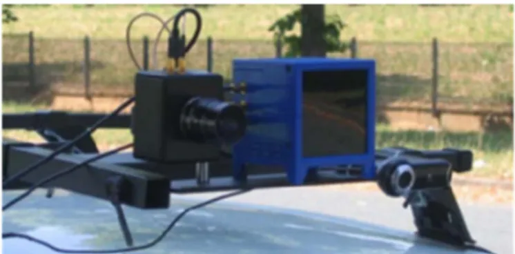
Fig, I: Picture of the 3D SPAD system (sensor module and laser illuminator), mounted on the roof of a car, together with a GoPro standard action camera,
A picture of the complete system (comprising the SP AD camera and the laser illuminator), mounted on the roof of a car, is shown in Fig. I. We also developed simple post processing algorithms for added information, such as profiles recognition and distance labelling, from the acquired videos.
A. SP AD-based Image Sensor
The proposed image sensor is based on a CMOS SP AD imager, which is controlled by an FPGA board for settings, data-readout, and USB data transfer. Each of the
64x32
pixels integrates a SP AD detector, a quenching circuit, shaping electronics, three 9-bit counters and their respective storage memories. Each SP AD features very good performance in terms of intrinsic noise (dark counts and afterpulsing), and about5%
efficiency at 808 nm [11]. The three 9-bit countersare used for in-pixel demodulation, providing respectively the counts C3-C), CO-C) and CO+C)+C2+C3, which are required by Eq.s
(2)-(4).
Thanks to in-pixel memories, the array works in a fully-parallel fashion: at the end of each frame, the output from each counter is stored into an in-pixel register, and a new frame can be acquired concurrently with the read-out of the previous one [10]. Thanks to this global shutter feature, the acquired image undergoes neither deformation (jello effect)nor motion artifacts, even in presence of fast moving objects. In order to operate the SP AD sensor chip, we developed a complete high-speed camera module composed by three printed circuit boards: a board hosting the chip, a board with a Spartan-3 FPGA and a third board in charge of generating power supplies and providing arbitrary analog waveforms modulation to the light source. The camera is housed in an aluminum case, supporting a 12 mm FII.4 C-mount imaging lens, whose field-of-view is about
40° x
20° (Hx
V). The whole camera is very rugged and compact, with 80 mmx
70 mmx 45
mm dimensions, and consumes about 1 W, mostly due to the FPGA.A MATLAB interface allows to set parameters (e.g. frame duration, number of frames to be acquired, modulation frequency, etc.) and to post-process data (see Sect. Ill-C).
B.
Continuous-wave illuminatorThe illuminator has a modular design based on a power-board and five laser driver cards, each one mounting 3 laser diodes with peak CW power of 200 m W at 808 nm
1 0.9 ....,. ::> 0.8 � 0.7 U> C :J 0.6 0 () 0.5 u <l> 0.4 .� 'iii 0.3 E 0 0.2 z 0.1
goo
816 818 Wavelength (nm)Fig. 2: Emitted light spectra of the 15 laser diodes, centered around 808 nm.
The current into each channel is controlled by two signals driven by the camera: the enable signal (EN) switches ON and OFF the current in the laser, while the Current control Input (el) is an analog voltage signal controlling the LD current.
As already explained in Sect. II, the maximum non ambiguous range is typically limited by the modulation frequency (the lower the modulation frequency, the longer the maximum range). On the other hand, low modulation frequencies have detrimental effects on the 3D-ranging precision. Therefore, in order to achieve the required range without degrading system performance, we adopted a double frequency continuous wave (DFCW) modulation, where each frame is acquired twice, using two different modulation frequencies, thus allowing to extend the maximum non ambiguous range (dMAx) without impairing measurement precision [12]. In our case, we implemented an 8.333 MHz (18 m range) and a 5 MHz (30 m range) modulation frequency, for achieving a final distance range of 45 m.
The illuminator performance plays a significant role in determining the final measurement precision and accuracy. For instance, the spectral cleanness of the illumination light sine wave, and in particular the presence of odd harmonics, has a direct impact on linearity errors. Moreover, another critical parameter is the modulation contrast (defined as the ratio between DC value and fundamental frequency amplitude, for a pure sinusoidal waveform), which needs to be maximized in order to minimize the contribution of the laser to the background DC light. Our illuminator features a very good 35 dB ratio between first and third harmonics power, and a nearly unitary modulation contrast. We also measured the emission wavelength of each of the 15 laser diodes, whose illumination spectra are plotted in Fig. 2 . The dispersion of the peak emission around the targeted 808 nm influences the
selection of the optical filters to be placed in front of the camera optical aperture. As the best compromise to optimize Signal-to-Background ratio, we chose the band-pass filter FB800-40 by Thorlabs (central wavelength 800 nm, 40 nm
full-width at half maximum).
Finally, it is important to observe that the interference of many illuminators belonging to different cameras does not prevent 3D measurements, but only slightly degrades the performance. In fact, different cameras' clocks, although running at same nominal frequencies, are not correlated; hence, the disturbing illumination contributes as a common mode signal that is rejected through the in-pixel demodulation.
3D Measurement Floor Subtraction
Fig. 3: Main steps of the post-processing algorithms. C. Post-processing
We conceived and implemented simple post processing algorithms in MATLAB, to recognize objects and mark their distance. The main steps are shown in Fig. 3. The top images
show the total background
B
(left) and the active light AI'(right) intensities. The middle ones show the 3D image after a two dimensional median filtering to improve the quality of the image (left) and after censuring pixels imaging the floor (right). For the floor cancellation, it can be intended as an object in the lower half part of the image, which is far from the camera in the middle rows of the image and it is close in the lower rows. If an object rises from the floor, it covers the floor behind it and the distance measurement in those pixels is less than in the case of only floor acquisition. With simple trigonometric equations it is possible to compute the expected distance of the floor for every pixel. If the distance evaluated for a pixel is less than that expected for the floor there is an object closer to the camera and the distance measurement is kept. On the contrary, the pixel is collecting light from a portion of the floor and the distance measurement is neglected. The bottom images represent the segmented image (left) and the superimposed 2D and 3D information, with pedestrian recognition and its distance marked and labelled (right). Both active-light image and 3D image are segmented in order to determine clusters of pixels relating to the objects in the scene. Every cluster holds information about the object which is connected to (horizontal and vertical dimensions, average/minimum/maximum distance, border shape, etc ... ).
All these information can be computed and displayed in real-time. Moreover, it is possible to track a single object in order to measure its speed with respect to the speed of the camera and eventually some information about the expected movements in front of the camera (e.g. by a Kalman filter).
Fig. 4: Typical automotive outdoor scenarios acquired with a standard action camera (top) and the SPAO camera (bottom), running at 100 fps.
IV. AUTOMOTIVE TESTS
The SP AD system (namely the SP AD camera and the illuminator source), was installed on a car, together with a standard action camera (Hero3 by GoPro) for co-registration (Fig. 1), and tested in real automotive scenarios.
Many measurements were performed during afternoon and evening hours, also in adverse (foggy and light rain) weather conditions, with less than 1,000 lux of background illumination, Fig, 4 shows two scenes, both acquired with the GoPro camera and with the SP AD camera running at
lOO
fps, i.e. with 10 ms frame-time. In Fig. 4 left, there are two pedestrians crossing the street at 7.2 m and 7.5 m respectively and a tram at 22 m; in Fig. 4 right, there are a pedestrian and a cyclist on the zebra crossings at 6 .8 m and 8.0 m and a car behind them at 11.7 m. As can be seen, even with the low 2048 pixels resolution of the SPAD camera, it is possible to identifY pedestrians and discriminate them from vehicles (e.g. cars or trucks) and other street signs, through some post processing. From our measurements, we can infer that the illumination system is able to uniformly illuminate the scene without shadow zones and, although the camera resolution is limited to 2048 pixels, the integration of all information provided by the SPAD sensor enables to generate images rich of details, thus allowing to locate and recognize objects in the scene through real-time image processing. A video, showing all the potentialities of the automotive 3D SPAD camera is available at [13].We performed other measurements in daylight conditions, with a background illumination of about 33,000 lux. In those measurements, the modulated signal reflected from the vehicles (�100 counts per frame, cpt) was overwhelmed by the background light (�
I
0,000 cpt) and only the light received from license plates and the tail lights (which are not lambertian reflectors, but retro-reflectors, as well as road signs) was high enough(�I,OOO
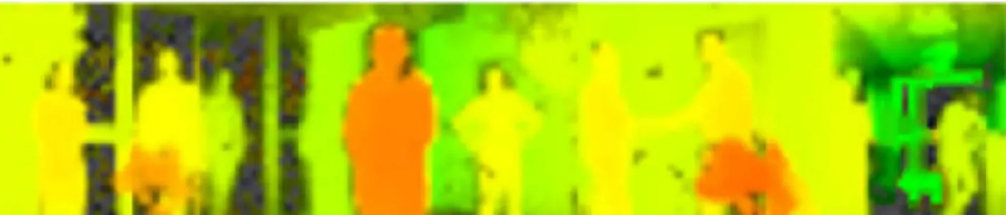
cpt) to allow distance detection.Thanks to superimposition of 2D and 3D information, cars and road signs may be accurately detected even with strong sunlight by using a proper image segmentation algorithm. To this aim, Fig. 5 shows a frame of a movie acquired by the SP AD camera with 100 flS frames and averaged over 100 frames, i.e. with a total equivalent 3D integration time of 10 ms, corresponding to 100 fps. As can be seen, seven pedestrians are standing in the scene at different distances, from 3.2 m up to 6 .2 m. The picture at the top shows the raw 3D acquisition, where the false colors represent the distance (see the scale on the right-hand side). Instead, the bottom picture shows the overlay of the 3D depth-resolved map with the 2D intensity map, obtained by computing the reflected light intensity AR of Eq. (3).
9 5.8 6.2 5.3 4.6 8 6 3
Fig. 5: Frame from a 3D movie acquired over-imposing the 3D map distance information with the 20 photon intensity, both provided concurrently by the SPAO camera.
"
Fig. 6: Horizontal multishots panorama of 3D ranging images over a 130° x 20° final field-of-view (targets were between 3 m and 10 m distance).
This simple overlay provides more information about the objects (e.g. the separation among face, sweater and trousers). The different colors represent different distances, while the different color luminosities identifY different reflected intensities. Therefore, the pedestrian in center position is in yellow false-color (corresponding to a 3D distance of 6 m), but hairs are dark, and trousers are more opaque than the shirt.
All measurements shown so far were acquired with the SP AD camera fixed on the vehicle roof, for ease of installation. In order to cover a larger field-of-view compared to the intrinsic 400 x 200 one, we implemented also a simple angular scanning. Fig. 6 shows a scene acquired in four consecutive shots over a 900 angular rotation (a final 1300 x 200 field-of-view) and the resulting panorama assembly of four 64x32 images, resulting in a 3D image of 210x32 pixels.
V. CONCLUSIONS
We have presented a 3D vision system based on a SPAD image sensor, manufactured in a cost-effective 0.35 flm automotive-certified CMOS technology and an 808 nm laser
illuminator. The active illuminator outputs low-power eye-safe light, thanks to SP AD detectors single-photons sensitivity in the near-infrared wavelength range. Each pixel of the 64x32 SP AD imager can acquire simultaneously 2D and 3D images from the scene under observation, through indirect Time-of Flight measurement, i.e. by counting photons in four time slots synchronized with the continuous-wave (CW-iTOF), sinusoid modulated, active illumination. We validated the 3D camera in real outdoor automotive scenario both under low ambient light condition « 1,000 lux) and in daylight (33,000 lux). In low ambient light scenarios, we acquired 3D maps of targets located up to 45 m away, in a field-of-view of 400 x 200, with better than 1 m precision at the farthest distance. We also over-imposed 3D depth-resolved maps with 2D intensity data, both concurrently provided by the SP AD camera, to augment data from the scene under observation. Finally, we operated the camera in an angular scanning system, to exceed the intrinsic field-of-view. For example, we reached a 1300 x 200 final field-of-view, by means of four angular scan and a resulting resolution of 21 Ox32 pixels.
For the future, we envision to further improve the camera functionalities and performance. For instance, object recognition will be implemented within the FPGA, in order to have a standalone system able to communicate over CAN bus with the vehicle control unit, to fulfill functional requirements of a collisions mitigation system.
ACKNOWLEDGMENTS
This work has been partially supported by the " DETS" project (Dependability Engineering Innovation for automotive CPS), funded by the European Union's Horizon 2020 research and innovation programme, under the grant no. 732242 .
VI. REFERENCES
[I] D. Bronzi, F. Villa, S. Tisa, A. Tosi, and F. Zappa, "SPAD Figures of Merit for photon-counting, photon-timing, and imaging applications,"
IEEE Sensors Journal, Vol. 16, No. I, pp. 3-12, Jan. 1,2016.
[2] R. Rasshofer and K. Gresser, "Automotive Radar and Lidar Systems for Next Generation Driver Assistance Functions," Adv. Radio Sci., vol. 3, no. 10, pp. 205-209, 2005.
[3] C. Veerappan, J. Richardson, R. Walker, D. Li, M.W. Fishburn, et al. "A 160x128 Single-Photon Image Sensor with On-Pixel 55ps lOb Time-to Digital Converter ", IEEE Int. Solid-State Circuits Conj, 2011. [4] M. Gersbach, Y. Maruyama, R. Trimananda, M.W. Fishburn, et al. "A
Time-Resolved, Low-Noise Single-Photon Image Sensor Fabricated in Deep-Submicron CMOS Technology," Journal of Solid-State Circuits, Vol. 47 no. 6, pp. 1394-1407, June 2012.
[5] F. Villa, R. Lussana, D. Bronzi, S. Tisa, A. Tosi, F. Zappa, A. Dalla Mora, D. Contini, D. Durini, S. Weyers, W. Brockherde, "CMOS imager with 1024 SPADs and TDCs for single-photon timing and 3D time-of f1ight ", IEEE Journal of Selected Topics in Quantum Electronics, Vol. 20, no. 6, Nov-Dec. 2014.
[6] R. Lussana, F. Villa, A. Dalla Mora, D. Contini, A. Tosi, and F. Zappa, "Enhanced single-photon time-ot:f1ight 3D ranging," Opt. Express, Vol. 23,pp. 24962-24973,2015.
[7] C. Niclass, C. Favi, T. Kluter, F. Monnier, and E. Charbon, "Single Photon Synchronous Detection," IEEE J Solid-State Circuits, vol. 44, no. 7, pp. 1977-1989, .luI. 2009.
[8] S. Bellisai, D. Bronzi, F. Villa, S. Tisa, A. Tosi, and F. Zappa, "Single photon pulsed-light indirect time-of-f1ight 3D ranging," Opt. Express,
vol. 21, no. 4, pp. 5086-5098, Feb. 2013.
[9] D. Bronzi, Y. Zou, F. Villa, S. Tisa, A. Tosi, and F. Zappa, "Automotive Three-Dimensional vision through a Single-Photon Counting SPAD camera," IEEE Transaction on Intelligent Transportation Systems, vol. 17, no. 3, March 2016.
[10] D. Bronzi, F. Villa, S. Tisa, A. Tosi, F. Zappa, D. Durini, S. Weyers, and W. Brockherde, "100,000 frarnes/s 64x32 single-photon detector array for 20 imaging and 3D ranging," IEEE J Selected Topics in Quant. Electronics, Vol. 20, No. 6, Nov.lDec. 2014
[11] F. Villa, D. Bronzi, Y. Zou, C. Scarcella, G. Boso, S. Tisa, A. Tosi, F. Zappa, D. Durini, S. Weyers, W. Brockherde, U. Paschen, "CMOS SP ADs with up to 500 11m diameter and 55% detection efficiency at 420 nm," Journal of Modern Optics, Jan. 2014.
[12] A. D. Payne, A. P. P. Jongenelen, A. A. Dorrington, M. J. Cree, and D. A. Carnegie, "Multiple frequency range imaging to remove measurement ambiguity," in Proc. Optical 3-D Measurement Techniques, pp. 139-148, Jul. 2009.
[13] D. Bronzi. (2014). SP-ADAS: High-Speed Single-Photon Camera for Advanced Driver Assistance Systems [Online]. Available: https://www.youtube.com/watch?v=OCBtMEG6X80 (accessed Feb. 2017.