Photocatalytic degradation of reactive dyes by visible light and
innovative Fe-doped titania catalysts.
Faculty of Civil and Industrial Engineering
Chemical, Material and Environmental Engineering Department PhD Course in Chemical Engineering
PhD Candidate
Marika Michela Monaco
Supervisor
Prof. Roberto Lavecchia
Index
List of Figures List of Tables
List of symbols and abbreviations
Summary and outline... 1
Chapter 1 – Introduction 1.1 Introduction... 3
1.2 Dyes and Pigments... 4
1.3 Dyes classification... 4
1.3.1 Reactive dyes... 5
1.3.2 Acid dyes... 5
1.3.3 Metal complex dyes... 5
1.3.4 Direct dyes... 6 1.3.5 Basic dyes... 6 1.3.6 Mordant dyes... 6 1.3.7 Disperse dyes... 7 1.3.8 Pigment dyes... 7 1.3.9 Vat dyes... 7 1.3.10 Sulphur dyes... 7 1.3.11 Solvent dyes... 8
1.4 Traditional methods for removal of dyes from wastewater... 9
1.5 Physical methods... 9
1.5.1 Activated carbon... 10
1.5.2 Peat... 10
1.5.3 Wood cheap... 10
1.5.5 Other materials... 10 1.5.6 Membrane filtration... 11 1.5.7 Ion exchange... 11 1.5.8 Irradiation... 11 1.5.9 Electrokinetic coagulation... 11 1.6 Biological treatments... 12
1.6.1 Decolorization by white-rot fungi... 12
1.6.2 Other microbial cultures... 12
1.6.3 Adsorption by living/dead microbial biomass ... 12
1.6.4 Anaerobic textile-dye bioremediation systems... 13
1.7 Chemical methods... 13 1.7.1 Oxidative process... 13 1.7.2 H2O2 + Fe(II) salts... 13 1.7.3 Ozonation... 14 1.7.4 Photochemical... 14 1.7.5 Sodium hypochloride... 15
1.8 New methods for removal of dyes from wastewater: Advanced Oxidation Processes... 15
1.8.1 The hydroxyl radical... 16
1.8.2 Electrochemical destruction... 16
1.8.3 Photocatalysis... 17
1.8.4 Homogeneous photocatalysis... 17
1.8.5 Heterogeneous photocatalysis... 17
1.9 Photocatalysts for heterogeneous photocatalysis... 19
1.9.1 Titanium dioxide... 20
1.9.2 Non-metal doping: N-doped TiO2... 21
1.9.3 Photosensitization... 22
1.9.4 Metal doping: Fe-TiO2... 23
1.10 Natural light sources and artificial light sources for photocatalysis... 24
1.10.1 Incandescence lamps... 24
1.10.2 Gas discharge lamps... 25
1.10.3 Fluorescent lamps... 25
1.10.4 LED lamps... 26
Chapter 2 – Literary review
2.1 Introduction... 28
2.2 Recent Advances in Synthetic Dyes Photocatalytic Decolorization... 28
2.3 Parametres affecting photocatalytic process... 38
2.3.1 Influence of Dye Type on the Photocatalytic Process...38
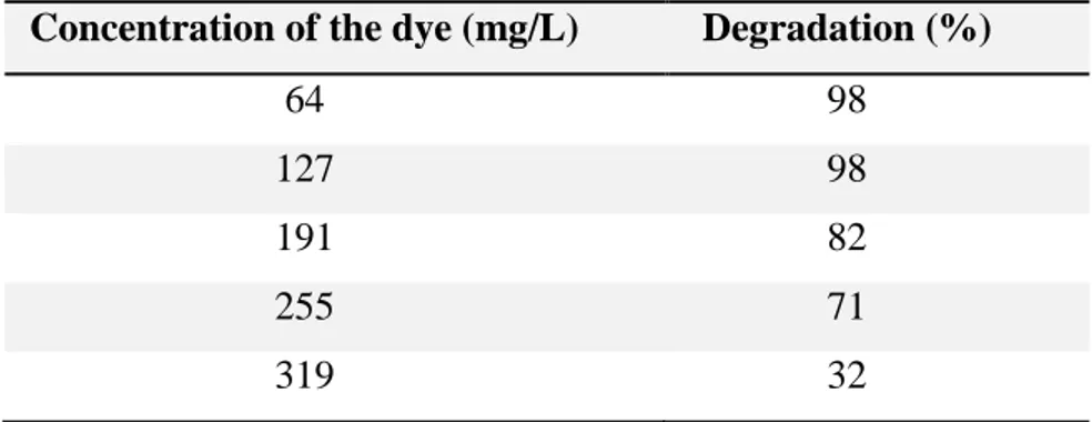
2.3.2 Dye concentration... 40
2.3.3 Catalyst loading... 41
2.3.4 pH... 41
2.3.5 Concentration of hydrogen peroxide... 43
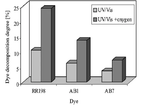
2.3.6 Aeration... 44
2.3.7 Type of light source: LEDs vs. conventional UV irradiation sources... 44
2.3.7.1 Advantages of LEDs... 45
Chapter 3 – Photocatalytic degradation of Reactive dyes under visible light 3.1 Introduction... 46
3.2 Chemicals and Reagents... 46
3.2.1 Dyes specifications... 47
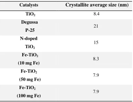
3.2.2 Catalysts specifications... 49
3.3 Equipment... 50
3.3.1 UV/VIS Spectroscopy... 50
3.4.Experimental procedure... 53
3.5 Kinetic modeling: Initial Rates Method... 55
3.6 Results and discussion... 56
3.6.1 Photolysis of Reactive Blue 4... 56
3.6.2 Photocatalyst selection... 56
3.6.3 Effect of pH on Reactive Blue 4 decolorization... 58
3.6.4 Comparison of photocatalytic efficiency of Fe-TiO2 (10 mg Fe) and TiO2... 64
3.7. Reactive Red 120... 66
3.7.1 Photodecolorizaton of Reactive Red 120: preliminary experiments.. 63
3.8.1 Photodecolorization of Reactive Violet 5: preliminary
tests... 68
3.8.2 Catalyst to dye concentration ratio of 10... 70
3.8.3 Catalyst to dye concentration ratio of 100... 72
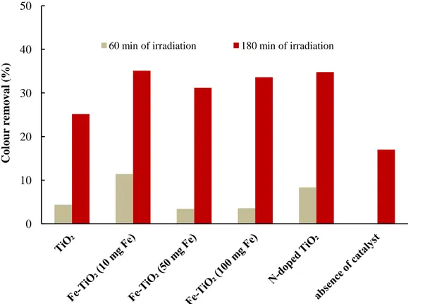
3.8.3.1 Photocatalyst selection... 72
3.8.3.2 Effect of pH... 76
3.8.3.3 Effect of catalyst concentration... 79
3.8.3.4 Effect of H2O2... 82
3.9 Discussion... 85
Conclusions and future developments... 87 Appendix A
Appendix B Appendix C
List of Figures
Figure 1.1 - Principle of cotton dyeing with a triazyl reactive dye... 5
Figure 1.2 – Molecular structure of various organic dyes... 8
Figure 1.3 - Conduction and valence bands and electron–hole pair generation in a semiconductor... 19
Figure 1.4 – Polymorphics forms of the TiO2... 19
Figure 2.1 - Photocatalytic decomposition of RR198, AB1 and AB7 under UV/Vis illumination and under illumination and simultaneous aeration at pH=2 [82]...44
Figure 3.1 – Molecular structure of Reactive Blue 4 dye... 48
Figure 3.2 – Molecular structure of Reactive Red 120 dye... 48
Figure 3.3 – Molecular structure of Reactive Violet 5 dye... 48
Figure 3.4 – Schematic UV-vis spectroscopy... 51
Figure 3.6 – Reactive Red 120 calibration curve... 52
Figure 3.7 – Reactive Violet 5 calibration curve... 53
Figure 3.8 – Experimental apparatus for photocatalytic tests: (1) magnetic stirrer; (2) photoreactor; (3) blue LEDs strip; (4) air device... 54
Figure 3.9 – Effect of blue LEDs on the Reactive Blue 4 decolorization, expressed as absorbance change at 595 nm (CRB4 = 100 ppm)... 56
Figure 3.10 – Influence of BL and BL/catalyst on the Reactive Blue 4 decolorization, evaluated at 60 and 180 minutes of irradiation (CRB4 = 100 ppm;
Ccatalyst: 1 g/L)... 57
Figure 3.11 – Effect of pH on the Reactive Blue 4 colour removal evaluated at 180 minutes of irradiation (CRB4 = 100 ppm; Fe-TiO2 (10 mg Fe) = 1 g/L; light source = BL)... 58
Figure 3.12 – Reactive Blue 4 degradation rate under different solution pHs (CRB4 = 20 ppm, Vs = 100 mL; Ccatalyst = 0.1 g/L [214])... 60
Figure 3.13 – Influence of pH on the rate of degradation of Acid Brown 14 (CAB14 =311 g/L; Ccatalyst = 2.5 g/L [215])... 61
Figure 3.14 – Absorption spectra of Reactive Blue 4 expressed as a function of the time (CRB4 = 100 ppm; Fe-TiO2(10 mg Fe) = 1 g/L; pH = 4; light source = BL)... 63
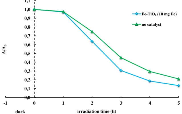
Figure 3.15 – Effect of BL and BL/catalyst on the Reactive Blue 4 decolorization, as a function of the irradiation time (CRB4 = 100 ppm; Ccatalyst = 1 g/L; light source = BL)... 64
Figure 3.16 – Effect of BL and BL/catalyst on the Reactive Blue 4 decolorization, as a function of the irradiation time (CRB4 = 300 ppm; Fe-TiO2(10 mg Fe) = 3 g/L; pH = 10; light source = BL)... 65
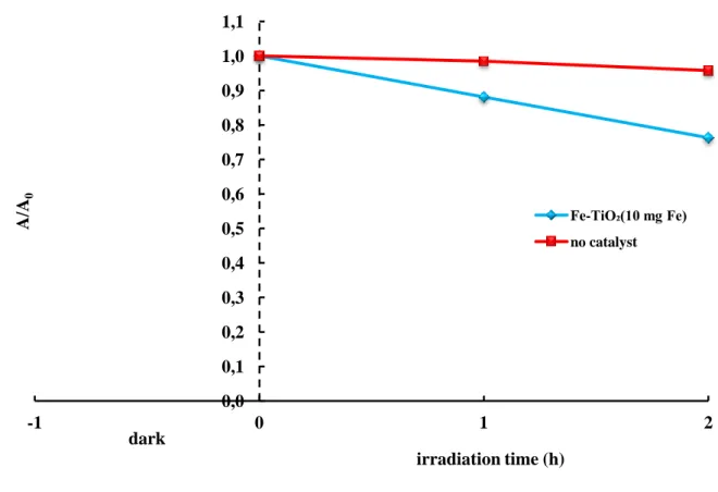
Figure 3.17 – Effect of photolysis and photocatalysis on Reactive Red 120 decolorization. (CRR120 = 100 ppm; pH = 10; Fe-TiO2(10 mg Fe) = 1 g/L; TiO2 = 1 g/L; light source = BL)... 67
Figure 3.18 – Effect of BL and BL/catalyst on the Reactive Blue 4 decolorization (CRB4 = 100 ppm; pH = 10; Ccatalyst = 1 g/L)... 68
Figure 3.19 – Effect of BL and BL/catalyst on Reactive Violet 5 decolorization (CRV5 = 100 ppm; pH = 10; Ccatalyst = 3 g/L)... 69
Figure 3.20 – Absorption spectra of Reactive Violet 5 (CRV5 = 100 ppm; pH = 10; Fe-TiO2(10 mg Fe) = 3 g/L; light source = BL)... 70
Figure 3.21 – Effect of BL and BL/catalyst on the Reactive Violet 5 decolorization (CRV5 = 100 ppm; Ccatalyst = 1 g/L; light source = BL)... 71
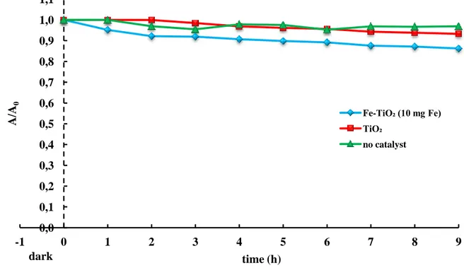
Figure 3.22 – Reactive Violet 5) photolysis and photocatalytic degradation in the presence of different catalysts (CRV5 = 30 ppm; Ccatalyst = 3 g/L; light source = BL)... 73
Figure 3.23 – Absorption spectra of Reactive Violet 5 solution (CRV5 = 30 ppm; Fe-TiO2(50 mg Fe) = 3 g/L; light source = BL)... 75
Figure 3.24 – Effect of pH on the Reactive Violet 5 photocatalysis (CRV5 = 30 ppm; Fe-TiO2(50 mg Fe) = 3 g/L; pH = (4 – 12); light source = BL)... 76
Figure 3.25 – Effect of pH on the Reactive Violet 5 decolorization evaluated after 9 hours of irradiation (CRV5 = 30 ppm; Fe-TiO2(50 mg Fe) = 3 g/L; light source = BL)... 77
Figure 3.26 – UV/vis spectra of Reactive Violet 5 solution (CRV5 = 30 ppm; pH = 4; Fe-TiO2(50 mg Fe) = 3 g/L; light source = BL)... 78
Figure 3.27 – Effect of the catalyst concentrations on the Reactive Violet 5 decolorization (CRV5 = 30 ppm; pH = 10; Fe-TiO2(50 mg Fe) = (0 – 6 g/L); light source = BL)... 79
Figure 3.28 – Rate constants evaluated for each catalyst concentration (CRV5 = 30 ppm; pH = 10; Fe-TiO2(50 mg Fe) = (0 – 6 g/L); light source = BL)... 80
Figure 3.29 – Trend of the inizial rate (m) of reaction as a function of the catalyst concentration (CRV5 = 30 ppm; Fe-TiO2(50 mg Fe) = (0 – 6) g/L; pH = 10; light source = BL)... 81
Figure 3.30 – Effect of H2O2 concentration on the Reactive Violet 5 decolorization, expressed as a function of irradiation time (CRV5 = 30 ppm; Fe-TiO2(50 mg Fe) = 3 g/L; H2O2 = (0 – 100) mM; pH 10; light source = BL)... 82
Figure 3.31 – Rate constant of reaction evaluated for each H2O2 concentration (CRV5 = 30 ppm; Fe-TiO2(50 mg Fe) = 3 g/L; H2O2 = (0 – 100) mM; pH 10; light source = BL)... 83
Figure 3.32 – Trend of the initial rate of reaction as a function of the hydrogen peroxide concentration (CRV5 = 30 ppm; pH 10; Fe-TiO2(50 mg Fe) = 3 g/L; light source = BL)... 84
List of Tables
Table 1.1 - Fixation degree of different dye classes on textile support... 9
Table 2.1 – Influence of the concentration of the dye on the Reactive Blue 4 degradation. Catalyst loading (2 g/L), energy source: solar light [171]...40
Table 3.1 – Dyes specifications...47
Table 3.2 – Catalysts specifications...49
Table 3.3 – Crystallite average sizes...49
Table 3.4 – Reactive Blue 4 decolorization percentages evaluated at 60 and 180 minutes of irradiation by BL, in absence and in presence of catalyst (CRB4 = 100 ppm; Ccatalyst = 1 g/L)...57
Table 3.5 – Reactive Blue 4 decolorization percentages, evaluated at 180 minutes of irradiation, as a function of pH (CRB4 = 100 ppm; Fe-TiO2(10 mg Fe) = 1 g/L; light source = BL)... 59
Table 3.6 – Reactive Blue 4 decolorization percentages achieved at 9 hours of irradiation (CRB4 = 100 ppm; Ccatalyst = 1 g/L; pH = 10; light source = BL)...65
Table 3.7 – Reactive Blue 4 removal percentages calculated after 5 hours of irradiation.(CRB4 = 300 ppm; pH = 10, Fe-TiO2(10 mg Fe) = 3 g/L; light source = BL)... 66
Table 3.8 – Reactive Violet 5 decolorization values, evaluated at 9 hours of irradiation, in the absence and in the presence of catalysts. (CRV5 = 100 ppm;
Ccatalysts = 1 g/L; light source = BL)...72
Table 3.9 – Reactive Violet 5 decolorization, evaluated after 9 hours of irradiation, in the absence and in the presence of catalysts (CRV5 = 30 ppm; Ccatalyst = 3 g/L; light source = BL)...73
Table 3.10 – Initial rate values calculated for each concentration of H2O2 (CRV5 = 30 ppm; Fe-TiO2(50 mg Fe) = 3 g/L; H2O2 = (0 – 100) mM; pH 10; light source = BL)...83
List of Symbols and abbreviations
RB4 — Reactive Blue 4 RR120 — Reactive Red 120 RV5 — Reactive Violet 5
CRB4 — Reactive Blue 4 concentration (ppm) CRR120 — Reactive Red 120 concentration (ppm) CRV5 — Reactive Violet 5concentration (ppm) LEDs — Light Emitting Diodes
BL — Blue Light Emitting Diodes k — rate constant (h-1)
m — initial rate constant (h-1) Abs — Absorbance
A/Ao — (Absorbance at time t / Absorbance at time 0) ID — inner diameter (cm)
H — height (cm) Qair — air flow (Lh-1) UV — ultra violet vis — visible
1
Summary and outline
Problem Formulation
Reactive dyes are the largest class of dyes used in the textile industry. They were selected for the present study because the treatment of wastewaters containing these dyes by conventional methods is often inadequate due to their resistance to biological and chemical degradation. The use of reactive dyes for textile dyeing has increased steadily over the last few years because of theirs cost effectiveness and excellent wash and light fastness properties. However, these dyes exhibit a very low degree of fixation on the fibers, typically between 50 and 90%, which results in the release of substantial amounts of the compounds in the dyeing water. The dyeing water cannot be reused, so dye recovery is not an option with reactive dyes. The high aromaticity and low reactivity of these dyes make them highly resistant to both microbial and chemical degradation. Physical treatments are not efficient because they transfer the toxic dyes from one medium to the other, without converting them to harmless non-toxic substances.
The development of novel treatment methods, called Advanced Oxidation Processes (AOPs), characterized by production of the hydroxyl radical (·OH) as a primary oxidant, could represent a solution. The application of these AOPs, alone or simultaneously, could enhance ·OH radical production leading to higher oxidation rates.
In this work, the photocatalytic oxidative decolorization of various reactive dyes, Reactive Blue 4, Reactive Red 120 and Reactive Violet 5, under exposure to visible light and in the presence of new semiconductor catalysts, was investigated.
The results suggest that Reactive Blue 4 is highly unstable under exposure to visible light, thus the presence of photocatalysts is not necessary for the degradation of this dye.
The Reactive Red 120 cannot be treated by direct irradiation and it cannot be decolorized even in the presence of photocatalysts.
The other results obtained indicate that the photocatalytic treatment under visible light can be an effective method for the removal of Reactive Violet 5from textile effluents.
2
To enhance the Reactive Violet 5 decolorization yields, the operational parameters such as pH, catalyst loading and hydrogen peroxide concentration, were optimized.
Work Accomplished
The work done in this study has been presented in three chapters as discussed in the following text.
In Chapter 1 the different types of dyes, particularly the reactive dyes, were described. The traditional methods (physical, biological and chemical) for removal of dyes from wastewaters were also described. Then, new methods for removal of dyes from wastewaters (Advanced Oxidation Processes) were reported. Among them, particular attention were given to the heterogeneous photocatalysis. The different types of catalyst and light sources that can be used, were also described.
In Chapter 2 the recent advances in synthetic dyes photocatalytic decolorization were reported. The parameters affecting the photocatalytic processes (dye type, dye concentration, catalyst loading, pH, concentration of hydrogen peroxide, aeration, light source) were described. A comparison between the traditional light sources and the new light sources, such as the LEDs, was also reported.
In Chapter 3 experimental procedures, description of reactor, instruments used and analytical techniques are discussed in detail. The decolorization of Reactive Blue 4, Reactive Red 120 and Reactive Violet 5, respectively, was studied. The influence of the type of catalyst, of pH, of catalyst concentration and hydrogen peroxide concentration, on the photocatalytic process was investigated. The optimal decolorization conditions were found. The results were compared with those obtained from other authors. Finally, the conclusions and recommendations for future works, were reported.
3
Chapter 1
Introduction
1.1 Introduction
Textile industries use over 10,000 different dyes and pigments, and over 200,000 tons of these dyes are lost to effluents every year during the dyeing and finishing operations, due to the inefficiency of the dyeing process [1, 2]. Unfortunately, many of these dyes persist in the environment because they have high stability to light, temperature, water, detergents, chemicals and soaps [3]. Moreover, many anti-microbial agents (resistant to biological degradation) are often, used in the manufacture of textiles, especially for natural fibers [3; 4]. The synthetic origin and complex aromatic structure of the dyes make them more recalcitrant to biodegradation [5, 6]. However, environmental legislation obliges industries to eliminate color from their dye-containing effluents, before disposal into water bodies [2; 4].
Dyes not only seriously affect the aesthetic quality and transparency of water bodies like lakes, rivers and others, leading to damage to the aquatic environment [7, 8], but also some of them can show toxic effects, especially carcinogenic and mutagenic events [9, 10]. The removal of the dyes is very difficult because they are designed to be resistant to biodegradation, thus they remain in the environment for a long period of time. For example, the half-life of the hydrolyzed dye Reactive Blue 19 is about 46 years at pH 7 and 25°C [11, 12]. Moreover, Carneiro et al. (2010), have monitored the dyes C.I. Disperse Blue 373 (DB373), C.I. Disperse Orange 37 (DO37) and C.I. Disperse Violet 93 (DV93) in environmental samples. They have found that DB373, DO37 and DV93 were present in both untreated river water and drinking water. This suggests that the traditional effluent treatments (pre-chlorination, flocculation, coagulation and flotation) generally used by drinking water treatment plants, was not completely effective in removing these dyes. The mutagenic activity detected in these effluents confirms these results [13].
4
1.2 Dyes and Pigments
Organic colorants can be distinguished in two classes, dyes and pigments [14]. They differ because dyes are soluble in water and/or organic solvents, while pigments are insoluble in both types of liquid media. Dyes are used to color substrates to which they have affinity. Pigments can be used to color polymeric substrates. The mechanism is different from that of dyes, because coloration involves the materials surface only.
1.3 Dyes classification
All the aromatic compounds absorb electromagnetic energy, but only those that absorb light with wavelengths in the visible range (~400-700 nm) are colored. A dye molecule is made up of chromophores, delocalized electron systems with conjugated double bonds, and auxochromes, electron-withdrawing or electron-donating substituents that can cause or intensify the color of the chromophore by modifying the energy of the electron system. Tipycal chromophores are ethylene group (-C=C-), carbon-nitrogen group (-C=N-), carbonyl group (-C=O), azo group (-N=N-), nitro group (-NO2) and aromatic rings.
Auxochromes are amino (–NH2), carboxyl (-COOH), sulphonate (-SO3H) and hydroxyl
(-OH) groups. There are about thirty different groups of dyes. They can be differentiated by the chemical structure or chromophore.
The chemical classification of dyes is based on the type of chromophore that is in the molecule (i.e. CI Constitution Number such as nitro, azo, carotenoid, diphenylmethane, xanthene, acridine, quinoline, indamine, sulphur, amino- and hydroxy ketone, anthraquinone, indigoid, phthalocyanine, inorganic pigment, etc.). The technical classification is based on the application technique of the dye (i.e. CI Generic Name such as acid, basic, direct, disperse, mordant, reactive, sulphur dye, pigment, vat, azo insoluble). Considering only the general structure, the textile dyes are also classified in anionic, nonionic and cationic dyes. The major anionic dyes are the direct, acid and reactive dyes. The major nonionic dyes are disperse dyes that does not ionised in the aqueous environment. The major cationic dyes are the azo basic, anthraquinone disperse and reactive dyes. Almost two-third of all organic dyes are azo dyes (R1-N=N-R2). They are used in a number
of different industrial processes such as textile dyeing and printing, color photography, finishing processing of leather, pharmaceutical and cosmethics.
Most notable azo-dyes are: acid dyes, basic dyes (cationic dyes), direct dyes (substantive dyes), disperse dyes (non-ionic dyes), reactive dyes, vat dyes and sulfur dyes.
5
1.3.1 Reactive Dyes
The reactive dyes form one of largest dye classes. Reactive dyes contain reactive groups that are able of forming covalent bonds between carbon atoms of dye molecule and OH-, NH-,
or SH- groups in fibres (cotton, wool, silk, nylon).
A reactive dye is characterized by its functional group. The reactive group can be a heterocyclic aromatic ring substituted with a chloride or fluoride atom. Another important reactive group is the vinyl sulphone (─SO3─CH═CH2) one.
During dyeing in alkaline conditions (i.e. pH 9-12), at high temperatures (30-70 ºC), and salt concentration from 40-100 g/L, reactive dyes form a reactive vinyl sulfone group, which creates a bond with the textile fibres (Figure 1.1). Anyway, the competition between the dye fixation reaction on the fibres and the undesired hydrolysis of the reactive group, results in a high loss of color (10–50%) in the resulting waters of the process. To increase the fixation degree of the dye on the fibres, different types of salts (up 60 to 200 g/L) can be added during the dyeing process.
Figure 1.1 - Principle of cotton dyeing with a triazyl reactive dye [250].
1.3.2 Acid dyes
Acid dyes are anionic compounds used in dyeing nitrogen-containing fabrics like wool, polyamide, silk and modified acryl [14, 243]. They bind to the cationic NH4+ ions of those
fibres. Acid dyes are typically applied to a textile at low pH, infact the term “acid” refers to the pH of the dyebaths. Acid dyes are caractherised by a high fixation degree: 80–95%.
6
1.3.3 Metal complex dyes
Among acid and reactive dyes, many metal complex dyes can be found. These are strong complexes of one metal atom (usually chromium, copper, cobalt or nickel) and one or two dye molecules, respectively.
1.3.4 Direct dyes
Direct dyes are mostly azo dyes with more than one azo bond or phthalocyanine, stilbene or oxazine compounds [14, 243]. Direct dyes were originally developed for theirs high affinity for cellulose fibres, and are water-insoluble. They can be used to dye polyester, but also nylon, cellulose triacetate, and acrylic fibers. They bind to the fibres through van der Waals forces. The dyes are, usually, finely ground in the presence of a dispersing agent to obtain a paste, or spray-dried to obtain a powder. Sometimes, a dyeing temperature of 130 °C, is required, and a pressurized dyebath is used. The dyeing rate can be influenced by the kind of dispersing agent used during the grinding.
1.3.5 Basic dyes
Most basic dyes are anthraquinone or azo compounds. Basic dyes are water-soluble cationic dyes [14, 244]. They can be used to dye acrylic fibers (they bind to the acid groups of the fibers), wool and silk. Acetic acid can be add to the dyebath to help the dyeing process. Basic dyes are also used in the paper industry.
1.3.6 Mordant dyes
Most mordant dyes are azo, oxazine or triarylmethane compounds. Mordant dyes require a mordant, a chemical that combines with the dye and the fiber. The choice of mordant is very important because different mordants can change the final color significantly.
The most important mordant dyes are the synthetic mordant dyes, or chrome dyes, used for wool. It is important to note that many mordants, particularly those in the heavy metal category, can be hazardous to health and extreme care must be taken in using them [244-248].
7
1.3.7 Disperse dyes
Disperse dyes are usually small azo or nitro compounds, anthraquinones or metal complex azo compounds. Disperse dyes are generally insoluble dyes. They can be used with synthetic fibers (cellulose acetate, polyester, polyamide, acryl, etc.) [243]. The dye diffusion requires swelling of the fibres, thus high temperatures ( > 120 °C) or chemical softners have to be used. Dyeing process takes place in dyebaths with fine disperse solutions of these dyes.
1.3.8 Pigment dyes
Pigment dyes are usually azo or anthraquinones compounds or metal complex phthalocyanines.
Pigment dyes (or organic pigments) are insoluble, non-ionic compounds or insoluble salts. Pigment dyes are used in aqueous solution so a dispersing agent is required. Pigments can be combined with thickeners in print pastes for printing diverse fabrics [1, 14].
1.3.9 Vat dyes
Vat dyes are essentially insoluble in water and incapable of dyeing fibers directly [244]. However, reduction in alkaline liquor produces the water-soluble alkali metal salt of the dye, which, in this leuco form, has an affinity for the textile fibre. Therefore, the soluble leuco vat dyes can impregnate the fabric. Subsequent oxidation reforms the original insoluble dye. The color of denim is due to indigo, the original vat dye. Vat dyes are anthraquinones or indigoids. They are usually used for dyeing cellulose fibers.
1.3.10 Sulphur dyes
Sulphur dyes are complex polymeric aromatics with heterocyclic S-containing rings. They are used to dye cellulose fibres [243].
The fabric is usually heated in a solution of an organic compound (sulfide or polysulfide or nitrophenol derivative) that reacts with the sulphur dye and forms a dark color that bind to the fibers.
8
1.3.11 Solvent dyes
Lysochromes or “solvent dyes” are nonpolar or weakly polar and they cannot be ionizated. Solvent dyes are not soluble in water but they are soluble in organic solvents, thus they are used to color hydrocarbon fuels, waxes, lubricants, plastics, and other hydrocarbon-based non-polar materials [1, 14].
Solvent dyes are usually diazo compounds, but con also be triarylmethane, anthraquinone and phthalocyanine solvent dyes.
Structures of some organic dyes from different classes are given in Figure 1.2.
9
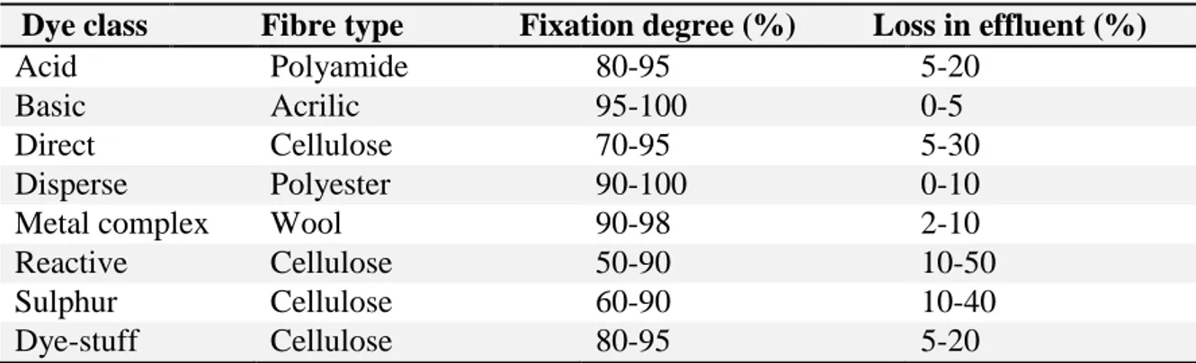
In Table 1.1 the fixation efficiency of some azo-dyes are reported.
Table 1.1- Fixation degree of different dye classes on textile support.
Dye class Fibre type Fixation degree (%) Loss in effluent (%)
Acid Polyamide 80-95 5-20
Basic Acrilic 95-100 0-5
Direct Cellulose 70-95 5-30
Disperse Polyester 90-100 0-10
Metal complex Wool 90-98 2-10
Reactive Cellulose 50-90 10-50
Sulphur Cellulose 60-90 10-40
Dye-stuff Cellulose 80-95 5-20
Table 1.1 shows that reactive dyes exhibit a very low degree of fixation on the fiber, typically between 50 and 90%, which results in the release of substantial amounts of the these dyes in the dyeing waters [86, 249] .
1.4 Traditional methods for removal of dyes from wastewater
Due to their synthetic nature and mainly aromatic structure, most of dyes are non-biodegradable, having carcinogenic action or causing allergies, dermatitis, skin irritation or different tissular changes. Moreover, various azo dyes, mainly aromatic compounds, show both acute and chronic toxicity. High potential health risk is caused by adsorption of azo dyes and their breakdown products (toxic amines) [9, 10, 14]. For these reasons, nowdays, government legislation regarding the removal of dyes from industrial effuents, is becoming more and more stringent, especially in developed countries.
This means that effluents must be treated before discharging into watercourses or water bodies in general. The treatment methods can be divided into three categories: chemical, physical and biological.
1.5 Physical methods
One of the most effective and economically advantageous is the adsorption. This process produces a high quality product [15]. Decolorization occurs both by adsorption and ion exchange [16] and it is influenced by many physio-chemical factors, such as dye/adsorbent interaction, sorbent surface area, particle size, temperature, pH, and contact time [17]. There are several types of adsorbent materials.
10
1.5.1. Activated carbon
Activated carbon is very effective for adsorbing different types of dyes: cationic, mordant, and acid dyes but it is less effective for treating dispersed, direct, vat, pigment and reactive dyes [19, 51]. The effectiveness of the process is strongly influenced by the type of carbon used and the characteristics of the wastewater. Activated carbon is not suitable for all types of liquid effluents, and it is also very expensive.
The activated carbon activity decreases during the time, so it needs to be reactivated. Reactivation, however, results in 10–15% loss of the sorbent.
1.5.2. Peat
Peat is able to adsorb transition metals and polar organic compounds from dye-containing wastewaters. Peat is cheaper than activated carbon, and does not need to be reactivated [20]. Due to its cellular structure, it has a large surface area, and good capacity for adsorption.
1.5.3. Wood chips
Wood chips are able to absorb acid dyes, but adsorption requires long contact time [20]. Moreover, wood chips are not as good as other available sorbents [21-23].
1.5.4. Silica gel
Silica gel is a granular, vitreous, porous form of silicon dioxide made synthetically from sodium silicate. Silica gel contains a nano-porous silica micro-structure, suspended inside a liquid. It is very effective for removing basic dyes, but it is not used commercially [249].
1.5.5. Other materials
Some substrates such as natural clay, corn cobs, rice hulls can be efficiently used for dye removal, especially because of their low cost and high availability. They are cheaper than activated carbon and they have often allowed achieving high removal yields [21-25]. These materials don’t require any regeneration.
11
1.5.6. Membrane filtration
This method is used to clarify, concentrate and separate dye continuously from effluents [26, 27]. It has better features than some other methods: resistance to temperature, an adverse chemical environment, and microbial attack. After separation, a concentrated residue is obtained; this is difficult to dispose. Some other problems can be represented by the clogging or the replacement of the membrane. Membrane filtration can be successfully employed for water re-cycling within a textile dye plant if the effluent contains low concentration of dyes, but it is not effective to reduce the dissolved solid content, which makes water re-use a difficult task.
1.5.7. Ion exchange
Wastewater passes trough the coloumn that contains the ion exchange resin until the available exchange sites are saturated. Ion exchange is mainly effective for removing anionic and cation dyes from dye-containing effuents. This method is not able for treating other dyes, such as disperse dyes [16, 26]. Ion exchange is very interesting because there is no loss of adsorbent during regeneration, but it remains an expensive method. Organic solvents are expensive, and the ion exchange method is not very effective for disperse dyes.
1.5.8. Irradiation
Organic pollutants, such as dyes contained in wastewaters, can be easly broken down by radiations, but a sufficient quantity of dissolved oxygen is required. Dissolved oxygen is consumed very rapidly; therefore, a constant supply is necessary. For this reason the process is very expensive. This method allowed obtaining high removal yields, at a laboratory scale, in treating some dyes and phenolic molecules [28].
1.5.9. Electro-kinetic coagulation
Electro-kinetic coagulation is an economically feasible method of dye removal. This method requires the addition of ferrous sulphate and ferric chloride. It is very effective for the removal of direct dyes from wastewaters. It is not suitable for treating of acid dyes because of the high cost of the ferrous sulphate and ferric chloride. This process is not commonly used, because the sludge formed as part of the coagulation is very difficult to remove [26].
12
1.6. Biological treatments
1.6.1. Decolorization by white-rot fungi
White-rot fungi are organisms able to degrade lignin, the structural polymer coming from woody plants [29]. White-rot fungi are also able to degrade dyes using enzymes, such as lignin peroxidases (LiP) or manganese dependent peroxidases (MnP). Other enzymes can be used to degrade dyes: glucose-1-oxidase and glucose-2-oxidase, along with laccase, and a phenoloxidase enzyme [30-32]. Azo dyes, can be successfully degraded by P. chrysosporium [33], but other fungi such as, Hirschioporus larincinus, Inonotus hispidus, Phlebia tremellosa and Coriolus versicolor can also be used [32, 35-37].
1.6.2. Other microbial cultures
The ability of bacteria to metabolise azo dyes were widely investigated. Mixed bacterial cultures from different habitats were able to decolorize the diazolinked chromophore of dye molecules in 15 days [38]. Some researchers [21-23] verified that a mixture of dyes could be decolorized by anaerobic bacteria in 24-30 h, using free growing cells or in the form of biofilms on various support materials. They also verified the use of bacteria for azo dye biodegradation [40]. Anyway, these microbial systems requires a fermentation process and cannot be used for treating large volumes of textile effluents. Azo dyes cannot be immediately metabolised under aerobic conditions, but it was found that Pseudomonas strains are able to aerobically degrade some azo dyes [41]. However, the intermediates coming from these degradative steps caused the disruption of metabolic pathways, thus the dyes were not actually mineralised. Under anaerobic conditions, many bacteria reduce azo dyes through the activity of unspecific, soluble, reductases, called azo reductases. These enzymes can cause the production of colorless aromatic amines which are toxic, mutagenic, and carcinogenic to animals.
Further research using mesophilic and thermophilic microbes also showed their ability to degrade and decolorize dyes [21-23, 35-37].
1.6.3. Adsorption by living/dead microbial biomass
Biosorption is the uptake or accumulation of chemicals by microbial mass [17, 42-44]. Dead bacteria, yeasts and fungi, can be used for treating dye-containing effluents. Different results can be obtained by varying the type of dye and biomass. Some dyes have a particular
13
affinity for binding with microbial species. For example it was observed that biomass derived from the thermotolerant ethanol-producing yeast strains, K. marxianus IMB3, showed a relatively high biosorption capacity for dye removal [45]. The biomass can be used especially if the dye-containing effluent is very toxic. Biomass adsorption can be successfully used when decolorization by microbial colture cannot be used [46]. It was demonstrated that bacterial cells are able to adsorb reactive dyes [42, 43]. Actinomyces were employed to adsorb anthroquinone, phalocyanine and azo dyes from wastewaters [47]. Biosorption is very quick: it requires few minutes in algae and few hours in bacteria [42, 43].
1.6.4. Anaerobic textile-dye bioremediation systems
Azo dyes represent almost 60-70% of all textile dyestuffs. These dyes are soluble in solution, and cannot be removed by conventional biological treatments. Reactive dyes, especially, are the most problematic compounds in textile effluents [48-50]. Anaerobic bioremediation is useful to decolorize azo and other water-soluble dyes. The process involves an oxidation-reduction reaction with hydrogen. (In aerobic systems free molecular oxygen is involved). The anaerobic degradation of a textile effluent only involves decolorization of the solution, but the dye molecule is not mineralized.
1.7 Chemical methods 1.7.1 Oxidative process
Oxidative process is the most common chemical method of decolorization. The main oxidising agent is usually hydrogen peroxide (H2O2). It needs to be preliminarily activated
by ultra-violet light or other sources. Many methods of chemical decolorization can be classified according to the activation mode of H2O2 [51]. The chemical oxidation of a dye
involves the opening of the aromatic ring of the dye molecule [52].
1.7.2 H2O2 + Fe(II) salts
Fenton’s reagent can be successfully used for treating textile wastewaters, which are resistant to biological treatment or are toxic to biomass [51]. One of the main drawback of this method is the sludge generation due to flocculation of the reagent and the dye
14
molecules. The sludge contains the concentrated impurities, so it requires to be disposed of. It can be generally incinerated to produce power, even though this step is not environmentally friendly.
1.7.3 Ozonation
Ozone is a powerful oxidising agent. It has an higher oxidation potential (2.07 V) than chlorine (1.36 V), and H2O2 (1.78 V). Ozonation can be used to degrade textile dyes,
chlorinated hydrocarbons, phenols, pesticides and aromatic hydrocarbons [53, 27]. The ozone dosage that can be utilised depends on the total color and total organic carbon (TOC) of the dye-containing effluents. Dyes have to be removed with no residue or sludge formation [54] and no toxic metabolites [55]. After ozonation an effuent with no color and low TOC (suitable for discharge into water bodies) is obtained [27]. This method gives good results especially when double-bonded dye molecules [51] are treated. Ozone can be used in its gaseus state so it does not increase the volume of wastewater and sludge.
A drawback of ozonation is its short half-life (about 20 minutes). This time decreases if dyes and salts are present in the treated solution, and it also depends on pH and temperature conditions. For example in alkaline conditions, ozone decomposition goes faster, so it is very important to regulate the effluent pH [51]. Results can be improved using irradiation [57] or with a membrane filtration technique [56]. A weakness of the process is its high cost, actually continuous ozonation is required due to its short half-life [27].
1.7.4 Photochemical
This method is able to degrade the dye molecules using the combined action of UV radiations and hydrogen peroxide [58, 59]. Dye molecules can be completely mineralized and form CO2 and H2O. Several literature studies carried out the degradation of commercial
dyes by UV/H2O2 in aqueous solutions. Enhanced efficiency of UV/H2O2 oxidation at
alkaline pH region was attributed to hydroxyl radical formation [60, 61]. It was also reported that the decolorization of C. I. Acid Black 1 decreased with increasing solution pH due to decomposition of H2O2 into water and oxygen rather than hydroxyl radical formation
[62-64]. A suitable H2O2 dosage showed enhanced performance of the process to degrade
crystal violet [65]. This process produces a high concentration of hydroxyl radicals that quickly degrade dye molecules. The process can be influenced by the intensity of the UV
15
radiation, pH, type of dye and dye-bath composition [32]. A drawback is the generation of by-products such as halides, metals, inorganic acids, organic aldehydes and organic acids [58]. This method does not generate sludge and it is effective for the odours removal.
1.7.5 Sodium hypochloride
Sodium hypochlorite (NaOCl) is a clear, slightly yellowish solution with a characteristic odour. It is used on a large scale for surface purification, bleaching, odour removal and water disinfection.
When sodium hypochlorite dissolves in water, two products are formed. They play an important role for oxidation and disinfection. These substances are hypochlorous acid (HOCl) and hypochlorite ion (OCl-). Hypochlorous acid is divided into hydrochloric acid (HCl) and oxygen (O). The oxygen atom is a very strong oxidator. The pH of the water determines how much hypochlorous acid is formed.
Sodium hypochlorite is used on a large scale. For example in agriculture, chemical industries, paint- and lime industries, food industries, glass industries, paper industries, pharmaceutical industries, synthetics industries and waste disposal industries. In the textile industry sodium hypochlorite is used to bleach textiles. It can also be added to industrial wastewater to reduce odours. Hypochlorite neutralizes sulphur hydrogen gas (SH) and ammonia (NH3) and detoxifies cyanide baths in metal industries. Hypochlorite can be used
to prevent algae and shellfish growth in cooling towers. In water treatment, hypochlorite is used to disinfect water. It also is effective against bacteria, viruses and fungi.
The use of chloridesfor dye removal is becoming less frequent due to the negative effects it has when released into waterways [51] and the release of aromatic amines which are carcinogenic, or otherwise toxic molecules [35-37].
1.8 New methods for removal of dyes from wastewater: Advanced Oxidation Processes Traditional methods for treating textile wastewaters are not very effective: biological methods require the use of micro-organisms whose activity is strongly inhibited by the levels of effluent toxicity. Physical methods only transfer dyes from one phase to another, but the problem still remains unsolved. The drawbacks of the chemical processes are the formation of sludge, its disposal and the space needed.
16
Advanced oxidation processes (AOPs) represent a new promising technology for the treatment of wastewaters containing recalcitrant organic compounds. All AOPs are designed to produce hydroxyl radicals. Hydroxyl radicals, in fact, are very effective to destroy organic compounds. AOPs are able to completely mineralise pollutants by converting them into water and carbon dioxide.
There are different types of AOPs, based on chemical, photochemical, sonochemical, and electrochemical reactions.
1.8.1 The hydroxyl radical
The hydroxyl radical is a powerful oxidant (HO∙ + H+ + e- → H2O). Its oxidation standard
potential is E° (∙OH/H2O) = 2.8 V/SHE [251]. This radical is able to quickly degrade
organic and organometallic pollutants until their complete mineralization into CO2, H2O and
inorganic ions. The hydroxil radical reacts rapidly with organics (R) mainly by the abstraction of a hydrogen atom (aliphatics) or the addition on an unsaturated bond (aromatics) to initiate a radical oxidation chain:
RH + ·OH → H2O + ·R (1.1)
·R + O2 → ROO· (1.2)
ROO· + RH → ROOH + ·R (1.3)
ArH + ·OH → ArH(OH)· (1.4)
ArH(OH)· + ·O2 → [ArH(OH)OO]· (1.5)
[ArH(OH)OO]· → ArH(OH) + HO2· (1.6)
1.8.2 Electrochemical destruction
The electrochemical oxidation is an efficient process for recovery and re-use of textile wastewater [66]. The efficiency of the process was comprovated by many studies: for a dyeing wastewater, a complete removal of the color was found within only 6 minutes of
17
electrolysis [67]. In conventional electro-oxidation processes, contaminants can be removed by direct oxidation, in which the pollutant is oxidized by electron transfer directly to the anode material, or indirect oxidation, in which the electron transfer is mediated by an oxidant species [68, 69] such as the hydroxyl radical (·OH) from water discharge. Contaminants may also be oxidized by other oxidants, such as active chlorine (Cl2, HClO,
and ClO-), S2O82−, and P2O84−, when chloride, sulphate, and phosphate containing solutions
are used, respectively [69]. The process is also influenced by the anode material and electrolysis conditions [71-74].
The electrochemical processes are able to remove the pollutants without adding chemicals. The main drawback of electrochemical processes is the use of electric energy that increases the costs.
The main advantages of this treatment are considered the requirement of simple equipment and operation, low temperature in comparison with other non-electrochemical treatments, no requirement of any additional chemicals, easy control but crucial for pH. Moreover, the electrochemical reactors (with electrolytic cells) are compact, and environmental friendly because all the emissions are minimized and undesired by-products are not generated.
1.8.3 Photocatalysis
In chemistry, photocatalysis is the acceleration of a photoreaction in the presence of a catalyst. Photocatalysis is a potential new method to eliminate recalcitrant organic compounds from wastewaters. It is based on physically and chemically induced processes. Photocatalysis can be homogeneous [60, 61, 64, 65] or heterogeneous [180].
1.8.4 Homogeneous photocatalysis
In homogeneous photocatalysis, the reactants and the photocatalysts exist in the same phase. The most commonly used homogeneous photocatalyst include hydrogen peroxide as it is reported in the paragraph (1.7.4).
1.8.5 Heterogeneous photocatalysis
Heterogeneous photocatalysis has the catalyst in a different phase from the reactants. Physically, heterogeneous photocatalysis involves a 4 - step process:
18
• transport of the pollutant from bulk of the solution onto the surface of the photocatalyst; • adsorption;
• photoreaction;
• desorption of final products from the surface to the bulk again. The photoreaction mechanism can be summarized as follows:
Photoexcitation: when a photocatalyst absorbs a photon of light having energy greater than its band-gap energy, an electron is promoted from the valence band of the irradiated particle to its conduction band, producing a positively charged hole in the valence band and an electron in the conduction band (Eq. (1.7)). These charges migrate to the particle surface and react with adsorbed species (Eqs. (1.14) and (1.15)). Both oxidation and reduction processes commonly take place on the surface of the photoexcited semiconductor photocatalyst.
Ionization of water: water molecules can react with photogenerated holes to produce hydroxyl radicals (Figure 1.3). Hydroxyl radicals attack the adsorbed organic molecules or those that are very close to the catalyst surface non-selectively causing them to mineralize (Eq. (1.13)).
Oxygen ionosorption: while the photogenerated hole reacts with surface bound water or OH- to produce the hydroxyl radical, the conduction band electron reduces absorbed oxygen to form superoxide radical anion (O2-·) (Eq. (1.10)). This
superoxide ion can not only take part in the further oxidation process but also prevents the electron-hole recombination (Eq. (1.8)).
Protonation of superoxide: the generated superoxide can be protonated forming hydroperoxyl radical (HO2·) (Eq. (1.11)) and then H2O2 which further dissociates to
highly reactive hydroxyl radicals (·OH) (Eq.(1.12)).
photocatalyst + hv e-CB + h+VB (1.7)
e-CB + h+VB energy (heat) (1.8)
h+VB + H2O ·OH + H+ (1.9)
e-CB + O2 O2-· (1.10)
19
H2O2 + e-CB OH- + ·OH (1.12)
Dye + ·OH CO2 + H2O(dye intermediates) (1.13)
Dye + h+VB oxidation products (1.14)
Dye + e-CB reduction products (1.15)
Figure 1.3 - Conduction and valence bands and electron–hole pair generation in a semiconductor.
1.9 Photocatalysts for heterogeneous photocatalysis
The oxidation reaction will occur if the valence band (VB) of the catalyst has a higher oxidation potential than the species that have to be treated. The redox potential of the valence band and the conductance band for several semiconductors ranges between +4.0 and -1.5 Volts versus Normal Hydrogen Electrode (NHE). Therefore, by choosing the suitable catalyst, it is possible to treat different species trough the photocatalytic processes. Metal oxides are semiconductor materials suitable for photocatalysis.
The wavelength of the light, required to activate a catalyst has to be equal or lower than that calculated by the Planck’s equation (Eq. 1.16):
λ=hc / Ebg (1.16)
where Ebg is the semiconductor band-gap energy, h is the Planck’s constant and c is the
20
The photocatalysts can be used under dispersed form (powder, aqueous suspension) or in thin film form (fixed catalytic layer) [226].
The dispersed catalysts present several advantages: they are easy to use, they possess an important specific surface, and they can be aerated to prevent the recombining of electron-hole pairs and increase the catalyst efficiency. However, a drawback of the dispersed form is the progressive formation of dark catalytic sludge, that diminishes the efficiency of light irradiation and reduces the photoreactor performances. In contrast, for the catalysts in form of film, there is no need to separate the catalytic particles at the end of the process, but, on the other hand, the catalytic layer has to be very stable and active.
The amount and type of catalyst to be used depend on the irradiation source, the nature and concentration of pollutants to be treated, and the photoreactor. The pH value of the medium have to be optimized according to the type of pollutant and to the type of catalyst.
1.9.1 Titanium dioxide
Titanium dioxide (TiO2) is a white powder semiconductor having a wide band gap of 3.0–
3.2 eV. TiO2 is one of the most suitable semiconductors for photocatalysis and it can be
applied into various photocatalytic reactions [75-85]. This is due to its high reactivity, aivalability, affordability, non-toxicity and photochemical stability. It can be excited by UV light with a wavelength below ca. 430 nm.
In general, titanium exists in three different polymorphic forms (Figure 1.4) including anatase (tetragonal), rutile (tetragonal) and brookite (orthorhombic). Rutile is the most stable phase, but, anatase, is the most commonly polymorphic form used in photocatalysis.
Figure 1.4 - Polymorphic forms of the TiO2[226].
Anatase phase is often found having particle size of 10 nm or less with a band gap of 3.2 eV corresponding to a UV wavelength of 385 nm. Rutile phase generally exists having particle
21
size in the order of 50 nm. Moreover, rutile has a smaller band gap of 3.0 eV with excitation wavelengths extending to visible 410 nm range.
TiO2 nanoparticles are widely available commercially or can be easily prepared using
sol-gel method. Heating the anatase phase results in a gradual phase transformation of anatase to rutile, thus, on the base of the method of preparation, mix phase anatase-rutile can be easily prepared or purchased [226].
If the source of irradiation is the UV light, the TiO2 can be used without any modification,
but, to use visible light, TiO2 needs to be modified by non-metal and/or metal doping, dye
sensitization, and coupling semiconductors.
1.9.2 Non-metal doping: N-doped TiO2
A drawback of TiO2 for photocatalysis is that its band-gap is rather large, 3.0-3.2 eV, and
thus only a small fraction of the solar spectrum (ʎ < 380 nm, corresponding to the UV region) can be absorbed. To reduce the energy for photoexcitation, the researches focused their attention on doping TiO2 with both transition metal (such as Fe, Cr, Co, Mo, and V)
and non-metal impurities (such as B, C, N, S, and F) [88-100]. Doping with transition metals showed positive and negative effects. Several authors reported that although metal ions doping decreases the photothreshold energy of TiO2, the metal ions may also serve as
recombination centers for electrons and holes, thus reducing the overall activity of the photocatalyst.
Recently, the interest in TiO2 doping with non-metal ions, especially with nitrogen, grew
considerably. N-doping can be obtained by various methods such as sputtering [101], treating of TiO2 powders in ammonia atmosphere [102], or hydrolysis with urea in the
presence of organic or inorganic titanium-based compounds [103, 104].
Besides the preparation procedures, many other aspects must be elucidated about the properties and behaviour of N-doped TiO2. First of all the chemical nature, the location in
the solid, and the involvement in photoactivity of the nitrogen species. Nitrogen can be found in different forms in chemical species, such as NOx [105-110], substitutional N
[111-114], or NHx [115]. It is important to know if the species are interstitial or substitutional,
because their behaviour is very different and might affect the material properties. It is also important to know if the species tend to segregate at the surface of the material or are incorporated in sub-surface or bulk sites, because this can influence the surface reactivity and photocatalytic properties.
22
Another aspect is the electronic structure of the doped material and the change of the optical gap [116, 117]. According to some authors, the band gap of the solid is reduced due to a rigid valence band shift after doping [118, 119], other authors claim that the absorption of visible light by N-doped TiO2 is due to the excitation of electrons caused by localized
impurity states in the band-gap [120, 121]. Also, the N-doping induced modifications of the electronic structure may be different for the anatase and rutile polymorphs of TiO2.
Another object of investigation is the interaction between N-impurities and oxygen vacancies. Some authors identified the role played by impurities (dopants, oxygen vacancies, hydroxyl groups) in the photo-activity of N-doped TiO2 samples. In their opinion,
the photocatalytic properties of TiO2, both in UV and vis-regions, can be largely improved
by tailoring the number and type of defects present in the photocatalyst.
The last and probably most important question for photocatalysis is the effect of N-doping on the photocatalytic activity of TiO2. A large part of the existing literature on N-doped
TiO2 materials agrees that the addition of nitrogen results in an improvement in visible light
photocatalytic activity, but this explanation is still controversial [116]. For example, in a recent study on N-doped TiO2 films obtained by the addition of ammonia during chemical
vapour deposition growth of TiO2 [122], no evidence of photocatalytic activity in the visible
was found.
1.9.3 Photosensitization
To extend the photocatalytic activity to the visible region, photocatalysts can be photosensitized by several colored organic and inorganic compounds. The most common method used for TiO2 photosensitization involves surface modifications.
This route is based on the formation of ionic or covalent bonds between the surface of a semiconductor and chromophores (sensitization mechanism). Several organic dyes, such as erythrosine B, porphyrines [149; 150], phtalocyanines [151; 152]) and metal complexes (with Fe(II) [42], Pt(IV) [153]), can be adsorbed on the TiO2 surface. These species are able
to absorb visible light and therefore promote an electron in the conduction band of the semiconductor. This mechanism is called photoinduced electron transfer and can be summarised as follow (Eq. (1.17); (1.18)):
TiO2---S+hν →TiO2---S* (1.17)
23
If the recombination step is eliminated, the oxidative degradation of the dye can start. Many colored compounds may act as photosensitizers. Recent studies suggest that photosensitized degradation on photocatalyst surfaces can be used for treating colored pollutants such as textile dyes.
1.9.4 Metal doping: Fe-TiO2
Metal doping is another way to improve the TiO2 photoefficiency. It consists in the
introduction of impurities able to attract one type of the photogenerated charges, e− or h+, reducing their recombination probability. Doping of the nanoparticles surface with iron, can be used to achieve this goal.
Fe3+ ions can act as shallow trapping sites for both photoinduced CB (conduction-band) electrons and VB (valence band) holes. As a result, the photoinduced charges can be better separated and conserved for a longer time. Consequently, the redox reactions of adsorbed species take place more efficiently. Iron is also considered an optimal doping agent because its radius (0.64 Å) is similar to that of Ti4+ (0.68 Å). Therefore, Fe ions can easily be incorporated with the crystal lattice of TiO2. The band-gap of iron is 2.6 eV, therefore, it
reduces the width of the energy gap of TiO2 and increases the efficiency of absorbing visible
light. The material properties of the Fe-doped TiO2 are strongly dependent on the crystal
structure, the size of the nanoparticles, and morphology, which are correlated with the TiO2
method of synthesis. There are several methods of synthesising Fe doped TiO2: sol–gel,
hydrothermal, wet chemical synthesis, thermal hydrolysis and plasma oxidative pyrolysis. There are also some combined methods, such as combining the sol–gel method with hydrothermal treatment.
Another reason to synthesise Fe-doped TiO2 is that TiO2 is not effective for degradation of
polymers. In fact, TiO2 is polar, while organic polymers are non-polar materials. For this
reason it is difficult to disperse TiO2 nanoparticles in the polymers. The nanoparticles of
TiO2 can be well dispersed in organic medium by surface modification with surfactants,
[123-125] coupling agents, [126, 127] or polymers, [128, 129], but, these modifications, could also reduce the catalytic activity of nano-catalyst. Although many methods have been proposed to prepare active TiO2, such as doping with metal ions [130-134] or non-metal
elements, [135-137] the surface property of nanoparticles is still polar. It is essential, for nano-TiO2, to display non-polar surface property as well as good catalytic activity. It was
24
found that nano-TiO2 displays better photocatalytic activity for degradation of methyl
orange after its surface was modified by complex of Fe(acac)3 [138].
These modifications not only increase the catalytic activity (the ferric complex acts as a photo-sensitizer), but also the surface oleophylicity (the ferric complex also acts as a surfactant). Hence, the modified TiO2 (Fe-TiO2) should be a suitable photocatalyst for
degradation of both polar and non-polar substances.
1.10 Natural light sources and artificial light sources for photocatalysis
Lamps are artificial sources of visible, UV, or both UV/visible light. Lamps, can generally be divided in:
Incandescence lamps;
Electric discharge lamps;
Fluorescent lamps;
LED lamps.
Radiations emitted by a natural source of light, such as the solar one, have a varying intensity according to the country, the season and the weather conditions, but have the disadvantage of being unidirectional.
1.10.1 Incandescence lamps
Incandescent lamps are made up of a base and a glass bulb containing a filament. An electric current flows through the filament making it incandescent, therefore it can emit radiant energy including the visible wavelengths. The filament usually contains tungsten, a metal having a very high melting point (3770 K), that can reach very high temperatures (2700-3000 K), ensuring high energy emissions with wavelengths in the visible field. The glass bulb also contains an inert gas, generally Ar or Kr, to limit the sublimation of the tungsten. The color temperature varies from 2700 K to 3000 K. The emissions are mostly in the IR and almost absent in the UV.
Halogen lamps represented a development of the incandescence lamps. They contain a gaseous mixture of halogen gas (generally iodine, bromine or chlorine) to avoid the evaporation of tungsten.
25
1.10.2 Gas discharge lamps
In discharge lamps, the production of light is caused by the emission of light radiations by a previously excited gas: when an electron returns to its stable orbit, a quantum of light energy is emitted. When an electron is excitated, it is promoted from its stable orbit to a more external one. The electron can be excitated by external energy sources, such as high-energy photons or other electrons accelerated by an electric field. Because of the properties of electronic orbits, the electronic orbits are defined: to a fixed energy correspond a well defined wavelength and a specific color. Gas discharge lamps are made up of a chamber, made of glass or quartz, which contains a gaseous substance at a suitable pressure. Generally, metallic vapours such as sodium, (with emission into the visible spectrum), mercury (with emission into the UV spectrum), xenon and other rare gases, (with emission in the UV spectrum) are used. On the base of the discharge tube pressure, these types of lamps can be divided into high and low pressure lamps. Low pressure mercury usually has an emission spectrum consisting of a pair of lines in the ultraviolet (at 254 and 185 nm.). High pressure mercury has an emission spectrum consisting of a pair of lines in the visible field (blue, green). If pressure is increased, the emission spectrum will become continuos, but the wavelengths corresponding to the red color are absent. Low pressure lamps are only used for scientific applications requiring UV radiations. There are also discharge lamps containing xenon as gaseous substance. Xenon allows obtaining an emission spectrum that reproduces the visible fraction of solar radiation. Xenon also has a strong UV emission, with several bands in the spectral range between 200 and 300 nm.
1.10.3 Fluorescent lamps
Fluorescent lamps use some substances (such as phosphors) able to absorb small wavelength electromagnetic radiations and to re-issue the relative energy in the form of longer wavelength radiations. These lamps exploit the emission of ultraviolet radiation from some gases and vapours (mainly mercury) used in discharge tubes. Here the fluorescence phenomenon is exploited, properties that have some substances (phosphors) to absorb small wavelength electromagnetic radiations and to re-issue the relative energy in the form of longer wavelength radiation. The inner surface of the glass chamber is treated with oxy-sulphides, aluminates, tungstates, phosphates and Ca, Mg, Zn silicate and heavy metals such as copper or antimony. Tubular fluorescent lamps usually contain argon, and a small amount of mercury, to facilitate the discharge start. This type of lamp is not suitable as UV sources.
26
1.10.4 LED lamps
A LED consists of a “p and n” type semiconductor junction. It is a p–n junction diode that emits light when activated. The p-n junctions in LEDs usually are made up of a mixture of Group III and Group V elements such as gallium arsenide, gallium arsenide phosphide, and gallium phosphide. In this p‐n junction, the p‐type region is dominated by positive charges and the n‐type region is dominated by negative charges. When a suitable voltage is applied across the LED’s electrical contacts, current flows and electrons move across the junction from the n‐type semiconductor region into the p‐type semiconductor region. Electrons then combine with positive charges. This effect is called electroluminescence, and the color of the light is determined by the energy band gap of the semiconductor.
When a combination occurs, a quantum of electromagnetic energy is released in the form of light. The frequency and, therefore, the apparent color of the emitted photons is characteristic of the semiconductor material. So, different color LEDs can be obtained by changing the semiconductor composition of the chip used.
Recently, LEDs were found to be an alternative for traditional light sources, and they were used in various application including UV curing, disinfection, sensors and photocatalytic applications [139-148]. LEDs generate cold light because of their low operating temperature. In fact, 5 mm LEDs are usually only 10–25 °C warmer than the ambient temperature during operation, whereas incandescent bulbs can be several hundred degrees warmer under similar conditions.
The energy of the photons that leave the diode depends on the material used to make the LEDs. At each wavelength of light corresponds a certain amount of energy. Shorter wavelengths (especially those close to UV) contain more energy. LEDs can produce light of different wavelengths including infrared, UV, and visible light.
1.11 Kinetics
It is very important to determine the reaction rate and the influence of different parameters on it. These parameters are: illumination intensity, catalyst type, oxygen concentration, pH, presence of inorganic ions and the concentration of organic reactants. Several experiments showed that the rate of photocatalytic oxidation of various organic pollutants over illuminated nanocatalysts fits the Langmuir–Hinshelwood (L–H) kinetics model equation [154]. The reaction rate is given by Equation 1.19:
27
= - / = 1k2 /(1+k2 ) (1.19)
where r is the oxidation rate of the dye (mg/L min), C is the bulk reactant concentration (mg/L), t the illumination time, k1 the reaction rate constant (mg/L min), and k2 is the
equilibrium adsorption constant (L/mg). For low solute concentration, the equation can be simplified to a pseudo first-order equation (Eqs. (1.20) and (1.21)):
= - / = 1k2 = (1.20)
Or
= C (1.21)
After a few steps the equation becomes:
ΔC/ C = (1- e-t/τ) (1.22)
where τ is the inverse of the apparent reaction rate constant: τ = 1/kapp .τrepresents the
expected value of time that a dye molecule remains in the solution before being removed.
kapp , the reaction rate constant, is not a traditional rate-constant. It is a function of external
system parameters such as light intensity, pH, catalyst loading, geometry of photoreactor and initial concentration of the pollutant.
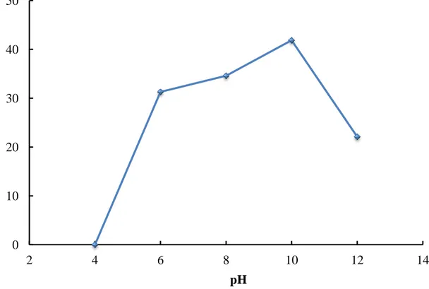
![Figure 3.13 - Influence of pH on the rate of degradation of Acid Brown 14 (C AB14 = 311 g/L; C catalyst = 2.5 g/L [215])](https://thumb-eu.123doks.com/thumbv2/123dokorg/2892233.11328/75.892.121.764.345.678/figure-influence-rate-degradation-acid-brown-ab-catalyst.webp)