1 Introduction 4
2 The FF-LYNX project 6
2.1 Genesis . . . 6
2.1.1 Introduction on High Energy Physics experiments . . . 6
2.1.1.1 Typical detector architecture . . . 9
2.1.1.2 Trigger signals . . . 9
2.1.1.3 Control and readout . . . 10
2.1.2 CERN’s Large Hadron Collider and its experiments . . . 11
2.1.2.1 The CMS experiment . . . 13
2.1.2.2 The ATLAS experiment . . . 16
2.1.3 Common features in DAQ/TTC systems for HEP experiments . . 18
2.2 Goals of the project . . . 20
2.3 Project design flow . . . 22
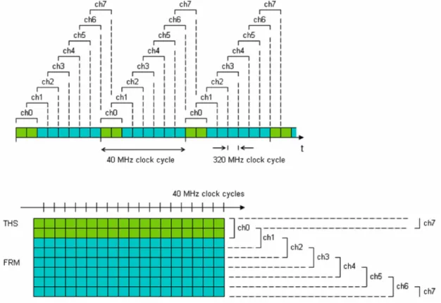
3 The FF-LynX protocol 26 3.1 General characteristics . . . 26 3.2 The THS channel . . . 30 3.2.1 TRG and HDR scheduling . . . 30 3.2.2 Synchronisation . . . 30 3.2.3 The THS encoding . . . 32 3.2.3.1 Hamming codes . . . 34
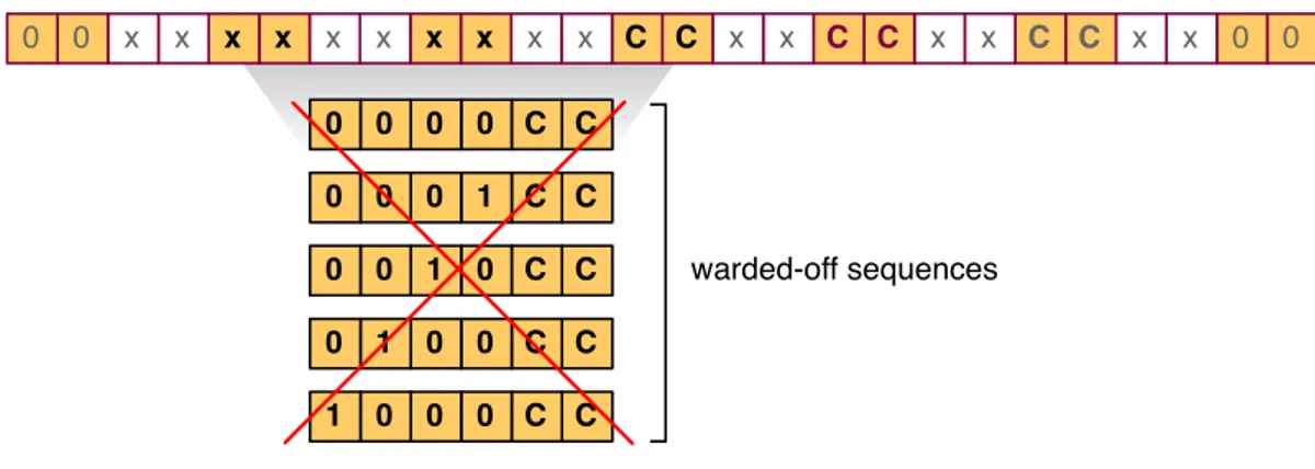
3.2.3.2 Original triple-codeword encoding . . . 37
3.2.3.3 Balanced encoding . . . 40
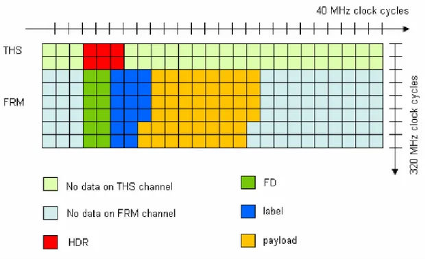
3.3 The FF-LYNX frame . . . 41
3.3.1 The Frame Descriptor . . . 43
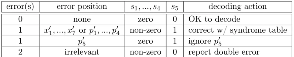
3.3.2 The Hamming(12,7) encoding . . . 44
3.3.3 Payload and label . . . 49
3.4 Future protocol features . . . 50
3.4.1 Interleaving . . . 50
3.4.2 CRC . . . 51
3.4.3 Single wire transmission . . . 51
3.4.4 DC balancing . . . 52
4 The FF-LYNX Interfaces 55
4.1 FF-TX . . . 55
4.1.1 Issuing trigger commands . . . 55
4.1.2 Supplying data packets . . . 57
4.1.3 Resulting output . . . 57
4.2 FF-RX . . . 58
4.2.1 Synchronisation management . . . 59
4.2.2 Receiving trigger commands . . . 60
4.2.3 Receiving data packets . . . 60
5 The High-Level Interface Model 63 5.1 The choice of the language . . . 63
5.1.1 SystemC vs. other languages . . . 63
5.1.2 Main SystemC features . . . 64
5.2 Model overview . . . 66 5.3 FF-TX . . . 66 5.3.1 Buffer . . . 68 5.3.2 Frame Builder . . . 71 5.3.3 Scheduler . . . 75 5.3.4 Serialiser . . . 79 5.4 FF-RX . . . 82 5.4.1 Deserialiser . . . 83 5.4.2 THS Finder . . . 87 5.4.3 Synchroniser . . . 91 5.4.4 Frame Analyser . . . 94 5.4.5 Buffer . . . 97 6 The Simulator 98 6.1 Possible physical configurations . . . 99
6.2 Packet generation . . . 100 6.2.1 Packet-oriented protocol . . . 100 6.2.2 Algorithm . . . 102 6.3 Trigger generation . . . 105 6.3.1 Algorithm . . . 105 6.4 Packet analysis . . . 105 6.4.1 Subrun-wise algorithm . . . 105 6.4.2 Run-wise algorithm . . . 108 6.5 Trigger analysis . . . 109 6.5.1 Subrun-wise algorithm . . . 109 6.5.2 Run-wise algorithm . . . 111 6.6 Error analysis . . . 112 6.6.1 Subrun-wise algorithm . . . 112 6.6.2 Run-wise algorithm . . . 112
6.7 Simulation Server . . . 113 6.7.1 Server Main . . . 114 6.7.2 Sim Interface . . . 114 6.7.3 Test Bench . . . 116 6.8 Simulation Client . . . 124 6.8.1 Client Main . . . 124
6.8.2 Sim Interface: Config Manager . . . 125
6.8.3 Sim Interface: Client Socket . . . 128
6.8.4 Sim Framework: Stim Gen . . . 128
6.8.5 Sim Framework: FoM Gauge . . . 130
6.9 Ancillary modules . . . 131 6.9.1 UfmEvent . . . 131 6.9.2 UfmRange . . . 132 6.9.3 EncDec . . . 132 6.10 Message format . . . 133 6.10.1 Protocol Buffers . . . 135 6.10.2 Defined types . . . 137
6.11 Running the simulator . . . 141
6.11.1 Command line . . . 142
6.11.2 Output . . . 143
7 The Test Plan 144 7.1 Figures of Merit . . . 144
7.1.1 Packets . . . 145
7.1.1.1 Corrupt packet descriptors rate . . . 146
7.1.1.2 Corrupt packet payloads rate . . . 146
7.1.1.3 Lost packets rate . . . 146
7.1.1.4 Packet latency . . . 147
7.1.2 Triggers . . . 151
7.1.2.1 Lost triggers rate . . . 151
7.1.2.2 Fake triggers rate . . . 152
7.2 The synchronisation problem . . . 152
7.2.1 Algorithm roundup . . . 154
7.2.2 Algorithm benchmark . . . 155
This thesis essay marks the first steps of the FF-LYNX project, a three-year endeavour endorsed and funded by the INFN V Commission to design and develop a new data transmission protocol suited to High Energy Physics (HEP) experiments and to provide its implementation in rad-hard low-power interfaces to be handed over to ASIC designers for embedment into their systems. FF-LYNX was born when INFN-PI1 and DII-IET2
joined efforts and put together their competences in developing radiation-tolerant integ-rated circuits and designing communication protocols. However, the project would have been a shot in the dark had it not relied on the collaboration of the world’s most im-portant particle physics research centre, CERN3. The project, started in January 2009
with little ambitions, has since gained momentum and its game-changing approach has sparked the interest of HEP communities. We dare call it game-changing because cur-rently HEP communities, even at CERN, pursue a “every man for himself” approach, where each laboratory develops its own solution to the problem of shifting data from the sensor array to the elaboration room. As shown later in Chapter 2, although the experiments each laboratory carries out might be sensibly different, they share common requirements. Therefore, custom, specialised solutions could be replaced by a single flex-ible protocol, saving time, money and especially brains, as the world’s brightest minds need not shift focus off unravelling the mysteries of universe. FF-LYNX is also spear-heading an engineered approach, following a strict project flow with carefully validated steps, in a context where R&D is completely haphazard. Chapter 7 describes our own validation process and points out how benchmarking our solution has been difficult be-cause even the main laboratories at CERN have never evaluated the performances of their solutions. The FF-LYNX project is foreseen to phase in over the next LHC (Large Hadron Collider) upgrades, scheduled for 2013 and 2018.
This thesis revolves around the definition and evaluation of the FF-LYNX protocol through a high-level model of the interfaces. A simulator, comprising the interface test bench and the apparatus to generate input signals and gauge the system performances, has then been developed. This covers the first phases of the project, throughly described at the end of Chapter 2. The successive steps involve creating a lower-level VHDL model of the interfaces and developing an FPGA emulator to perform more accurate tests before progressing to the first silicon test chip. The simulator is designed to allow its reuse during the FPGA prototyping phase. Thanks to its modular structure, the stimuli
1
Istituto Nazionale di Fisica Nucleare Pisa, lit. National Institute for Nuclear Physics, Pisa branch. 2
Dipartimento di Ingegneria dell’Informazione: Informatica, Elettronica e Telecomunicazioni, lit. In-formation Engineering Dept.: Informatics, Electronics and Telecommunications (University of Pisa). 3
Organisation Européenne pour la Recherche Nucléaire, lit. European Organisation for Nuclear Re-search (Geneva, Switzerland).
generation and performance analysis modules of the simulator will be left untouched, while the FPGA emulator will act as a drop-in replacement for the interface test bench and model. This will allow more extensive tests than it is currently possible even with the power of INFN’s computing grid.
As said before, Chapter 2 describes the state of the art of HEP experiments, explains the reasons that sparked the FF-LYNX project and details the project flow and its current progress. Chapter 3 thoroughly describes the current version of the FF-LYNX protocol and its foreseen upgrades. Chapter 4 gives a rundown on the external behaviour defined for the interfaces, of which the SystemC model, illustrated in Chapter 5, provides a high-level implementation. Chapter 6 details the inner workings of the aforementioned simulator and, finally, Chapter 7, describes how the simulator has been put into use to support critical design decisions by evaluating the expected performances in which different choices would have resulted.
This part provides an in-depth presentation of the FF-LYNX project. The FF-LYNX project, approved and funded by the INFN V Commission, started in January 2009 and, with its foreseen three-years long activity, aims at developing an integrated and scalable system for data acquisition and control in High Energy Physics (HEP) experiments. To this end, the project defines a new communication protocol from scratch and will provide an implementation in radiation-tolerant low-power interfaces to be handed over to ASIC designers for embedment into their systems.
Section 2.1 details the genesis of the project, while Section 2.2 illustrates the goals at which the project aims. Finally Section 2.3 presents the methodology chosen for the project activities.
2.1 Genesis
FF-LYNX originated from the experience of INFN in the field of HEP experiments and from the collaboration between INFN and the most important particle physics labor-atories and research centres (i.e. CERN, Fermilab, etc.). In this pool of different but somewhat similar contexts need arose for a data transmission protocol fulfilling all the typical HEP requirements which could be elected a standard. Using a single, highly engineered and flexible protocol in all the HEP experiments would enable savings on upkeep costs and minimise the time and efforts to set up an experiment. FF-LYNX is based on INFN’s experience in the design and development of Silicon and Gas detect-ors and radiation tolerant Integrated Circuits and DII-IET’s expertise in communication protocols and interfaces for space applications.
2.1.1 Introduction on High Energy Physics experiments
Particle physics is the branch of physics that studies the very constituents of matter and their interactions. Modern particle physics research is focussed on subatomic particles (i.e. particles with dimension and mass smaller than atoms), including atomic constitu-ents such as electrons, protons and neutrons, and particles produced by radiative and scattering processes, such as photons, neutrinos and muons. Since many elementary particles do not occur under normal circumstances in nature, to allow their study they are generated and detected by voluntarily causing high energy collisions between other particles in particle accelerators. For this reason, particle physics is often referred to as High Energy Physics (HEP). The purpose of particle physics is to investigate the funda-mentals of matter in order to address unanswered key questions about nature and origin of the Universe, such as symmetries in physical laws, the origin of mass, the nature of
dark matter and dark energy, possible existence of extra dimensions and so on; the final, ambitious objective would be the creation of a general theoretical model that is able to describe and explain all physical phenomena in an unified and coherent vision.
Particle accelerators are the key instruments for HEP research. These colossal and colossally complex machines produce beams of particles and provide them with the high energies needed for HEP experiments. Accelerators typically employ electric fields to increase kinetic energy of particles and magnetic fields to bend and focus the beam, which is then made to collide against a fixed target or another particle beam: the high energy collision produces the new particles and events to be detected and studied. Beside the use in particle physics, the applications of accelerators nowadays span from industry (e.g. ion implantation in electronic circuits) to medicine (i.e. radiotherapy), with each different field of application employing different energy levels. Current accelerators for High Energy Physics work in the GeV and TeV energy range (referring to the energy provided to particle beams) and typically treat beams of electrons, hadrons and heavy atomic nuclei; the structure can be linear (LINAC, LINear ACcelerator), with the particle beam travelling from one end to the other and colliding against a fixed target, or circular (cyclotrons, synchrotrons), with the beams travelling repeatedly around a ring, gaining more and more energy each loop and colliding with other beams running in the opposite direction.
The major research centres for High Energy Physics nowadays include, among the others:
• the European Organisation for Nuclear Research (CERN), located near Geneva, Switzerland: its main facilities included LEP (Large Electron Positron collider), which was dismantled in 2001 and substituted with LHC (Large Hadron Collider) that is now the world’s most powerful accelerator;
• the Deutsches Elektronen Synchrotron (DESY), located in Hamburg, Germany: its main structure is HERA, which is specialised in collisions of electrons, positrons and protons;
• the Fermi National Accelerator Laboratory (Fermilab), located near Chicago, IL, U.S.A.: its main facility is the Tevatron, which studies the collisions of protons and antiprotons;
• the Stanford Linear Accelerator Center (SLAC), located near Palo Alto, CA, U.S.A: it employs the longest linear accelerator in the world to have electrons and positrons collide;
• the INFN (Istituto Nazionale di Fisica Nucleare) centre in Frascati, Italy, that hosts the DAΦNE (Double Annular ring for Nice Experiments) a circular accelerator for the collision of electrons and positrons.
Figure 2.1: aerial view of the Stanford Linear Accelerator Center (SLAC)
2.1.1.1 Typical detector architecture
Despite all the possible differences in employed equipment and studied phenomena, all the High Energy Physics experiments still share the common denominator of particle beams collisions inside an accelerator. Around the collision point, particle detectors gauge the results of the interactions. Particle detectors can track and identify high-energy particles produced in collisions, also measuring their attributes like momentum, charge and mass. A particle detector is typically made up of different layers of sub-detectors, each one specialised in revealing and measuring different particles and properties: normally at the innermost layer (i.e. the nearest to the interaction point) sits the tracking device, which has the task of revealing the paths of electrically charged particles by looking at the trails they leave behind. The outer layers typically feature calorimeters, which measure the energy lost by particles travelling across them. To ease the identification of the particles produced in the collisions, the detector usually includes a magnetic field that bends the path of charged particles: from the curvature of the path, it is possible to calculate the momentum of the particle which helps in identifying its type. Particles with very high momentum travel in almost straight lines, whereas those with low momentum move forward in tight spirals.
2.1.1.2 Trigger signals
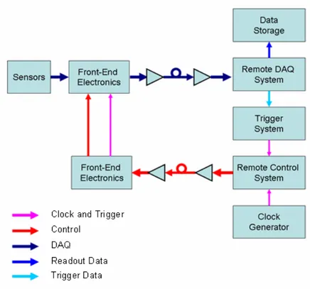
To record and analyse events produced by collisions in an experiment, information about particles detected by sensors in the detector are converted into electric signals, which are then collected by dedicated electronic components embedded in the detector and located in close contact with the sensors themselves: these devices, usually called Front-End (FE) electronics, deal with the proper conditioning of signals (e.g. amplification, shaping, buffering, analog to digital conversion) and their transmission to remote data acquisition systems that perform data analysis and storage. However, some means is needed to reduce the amount of data to be transferred from the detector to the remote system which is extremely large in every HEP experiment. In fact, to increase the probability of occurrence of rare, interesting events, the number of interactions per second is made very high (a typical order of magnitude is billions of particle interactions per second); a measure of collision rate is the so-called luminosity, which is usually expressed as cm−2s−1
and for a two-beam collider is defined as the number of particles per second in one beam multiplied by the number of collisions per unit area in the other beam at the crossing point. Collision rates of this order of magnitude produce amounts of raw data that range from tens of terabyte to a petabyte per second, which is beyond the possibilities of any data acquisition and storage system. Therefore, a filtering method is employed, which takes advantage of the fact that interesting events are a very small fraction of the total. This filtering method relies on a trigger system: raw data is temporarily buffered in the FE electronics while a small amount of key information is sent to the trigger processors (organised in a hierarchy inside the detector and in the remote elaboration centre) to perform a fast, approximate calculation and identify significant events. A trigger signal is thus sent back to the FE electronics to command a data readout of the deemed-worthy
!
!
!"#$%&$'%(%"#$%&'(!')&*%+,&+-),!./!!+*,!&.0+).(!'01!),'1.-+!2#2+,3!/.)!'!456!,7$,)%3,0+8!!!
9%:0'(2!:,0,)'+,1!;#!+*,!%0+,)'&+%.0!<%+*!2,02.)2!./!$')+%&(,2!$).1-&,1!%0!+*,!;,'3!&.((%2%.02!'),!
*'01(,1!;#!=).0+>501!,(,&+).0%&2!,3;,11,1!%0!+*,!1,+,&+.)2!'01!.$+%&'((#!+)'02/,)),1!+.!),3.+,!1'+'!
'&?-%2%+%.0!@ABCD!2#2+,32E!+*'+!'),!$('&,1!/')!'<'#!/).3!+*,!,7$,)%3,0+F2!'),'!+.!G,,$!+*,3!%0!'0!
,0H%).03,0+!+*'+!%2!/),,!/).3!+*,!%0+,02%H,!(,H,(2!./!)'1%'+%.0!+*'+!%2!$),2,0+!%0!+*,!$).7%3%+%,2!./!
+*,! %0+,)'&+%.0! $.%0+I! +#$%&'((#! +*,! +)'02/,)! %2! &'))%,1! .-+! ;#! 3,'02! ./! ,(,&+)%&'(! (%0G2! /.)! '! /%)2+!
2+),+&*! %02%1,! +*,! 1,+,&+.)E! '01! +*,0! +*).-:*! .$+%&'(! (%0G2! +*'+! '((.<! +.! &.H,)! +*,! (.0:! 1%2+'0&,2!
@*-01),1!./!3,+,)2D!/).3!+*,!,7$,)%3,0+F2!'),'!+.!+*,!),3.+,!ABC!2#2+,3E!'01!$).H%1,!+*,!('):,!
;'01<%1+*! 0,,1,1! @-$! +.! +,02! ./! J;%+K2D8! B! 2-;2,+! ./! +)'02/,)),1! 1'+'! %2! -2,1! +.! $,)/.)3! +)%::,)!
&'(&-('+%.0E! '01! +*,! :,0,)'+,1! +)%::,)! &.33'01! %2! 2,0+! ;'&G! +.! =5! ,(,&+).0%&2! '(.0:! <%+*! +%3%0:!
@&(.&GD! '01! &.0+).(! 2%:0'(2! ;#! '! ),3.+,! &.0+).(! 2#2+,3E! '(2.! &'((,1! ""L! @"%3%0:E! ")%::,)! '01!
L.0+).(D! 2#2+,3E! +*'+! ! 3'0':,2! ! +*,! &.0/%:-)'+%.0! '01! 3.0%+.)%0:! $).&,22,2! %0! +*,! =).0+>501!
,(,&+).0%&28!
4%:*!50,):#!6*#2%&2!,7$,)%3,0+2!&.02+%+-+,!'!H,)#!&*'((,0:%0:!'$$(%&'+%.0!/.)!,(,&+).0%&2E!2%0&,!
+*,!,?-%$3,0+!3-2+!1,'(!<%+*!('):,!'3.-0+2!./!1'+'!'01!*%:*!1'+'!)'+,2E!<%+*!+%:*+!+%3%0:!'01!1'+'!
%0+,:)%+#!&.02+)'%0+2!'01!.$,)'+,!%0!'0!,0H%).03,0+!+*'+!%2!%0+)%02%&'((#!*.2+%(,!1-,!+.!+*,!*%:*!(,H,(2!
./! )'1%'+%.08! "#$%&'(! ),?-%),3,0+2! /.)! 1,+,&+.)! ,(,&+).0%&2! '01! 1'+'! +)'023%22%.0! (%0G2! %0! '! 456!
,7$,)%3,0+!'),I!
> )'1%'+%.0! *')10,22I! ,(,&+).0%&! 1,H%&,2! '01! 2#2+,32! 3-2+! +.(,)'+,! *%:*! (,H,(2! ./! %.0%M%0:!
)'1%'+%.02!'01!+*,!'22.&%'+,1!".+'(!A.2,!5//,&+2!@,8:8!+*),2*.(1!H.(+':,!1)%/+!'01!2-;>+*),2*.(1!
&-)),0+!%0&),'2,!%0!NO9!1,H%&,2D!'01!9%0:(,!5H,0+!5//,&+2!@,8:8!9%0:(,!5H,0+!P$2,+!%0!/(%$>
/(.$2!'01!9QBN!&,((2DR!
> 23'((!2%M,I!+*,!2$'&,!'H'%(';(,!/.)!1,H%&,2!'01!&';(%0:!%02%1,!'!$')+%&(,!1,+,&+.)!%2!-2-'((#!H,)#!
(%3%+,1!1-,!+.!+*,!('):,!'3.-0+!./!1%//,),0+!&.3$.0,0+2!@),'1.-+!'01!&.0+).(!2#2+,32E!&..(%0:!
2#2+,32E!3,&*'0%&'(!2+)-&+-),2!'01!2.!.0D!+*'+!3-2+!;,!%0+,:)'+,1!%0!'!23'((!'),'!').-01!+*,!
%0+,)'&+%.0! $.%0+R! '11%+%.0'((#E! ;-(G#! ,?-%$3,0+2! '),! -01,2%),1! ;,&'-2,! '0#! 0.0>2,02.)!
3'+,)%'(! %0+,)/,),2! <%+*! +*,! 3,'2-),! ;#! 1,/(,&+%0:! '01! ';2.);%0:! +*,! $')+%&(,2! +*'+! 3-2+! ;,!
1,+,&+,1! @+*,! '3.-0+! ./! 3'+,)%'(! 2-)).-01%0:! +*,! %0+,)'&+%.0! $.%0+E! &*')'&+,)%M,1! <%+*! +*,!
)'1%'+%.0!+*%&G0,22!./!,'&*!&.3$.0,0+K('#,)E!%2!-2-'((#!),/,)),1!+.!'2!!"#$%&"'()*+,$#DR!
Figure 2.3: a typical DAQ architecture in HEP experiments
events only. This way, the amount of data to be transferred is considerably reduced and the data rates involved are manageable by the readout system (a typical order of magnitude is hundreds of MB/s from each FE device).
2.1.1.3 Control and readout
Signals generated by the interaction between the sensors and the particles produced in the beam collisions are handled by Front-End electronics embedded in the detectors and transferred to remote data acquisition (DAQ) systems, which are placed far away from the experiment area to keep them in an environment radiation-free environment (the interaction point is filled with radiation comparable with that of the nucleus of a nuclear power plant). Typically the transfer is carried out by means of electrical links for a first stretch inside the detector, then multiple electrical links are converged into high-bandwidth (10+ Gbit/s) optical links to cover the long distances (100+ meters) from the experiment area to the remote DAQ system. A subset of transferred data is used to perform trigger calculation and the generated trigger command is sent back to the FE electronics along with timing (clock) and control signals by a remote control system, also called TTC (Timing, Trigger and Control) system, that manages the configuration and monitoring processes in the Front-End electronics (see Figure 2.3).
High Energy Physics experiments constitute a very challenging application for
tronics, since the equipment must deal with large amounts of data and high data rates, with tight timing and data integrity constraints and operate in an environment that is intrinsically hostile due to the high levels of radiation. Typical requirements for detector electronics and data transmission links in a HEP experiment are:
• radiation hardness: electronic devices and systems must tolerate high levels of ionising radiations and the associated Total Dose Effects (e.g. threshold voltage drift and sub-threshold current increase in MOS devices) and Single Event Effects (e.g. Single Event Upset in flip-flops and SRAM cells),
• small size: the space available for devices and cabling inside a particle detector is usually very limited due to the large amount of different components (readout and control systems, cooling systems, mechanical structures and so on) that must be integrated in a small area around the interaction point; additionally, bulky equip-ments are undesired because any non-sensor material interferes with the measure by deflecting and absorbing particles (the amount of material surrounding the inter-action point, characterised with the radiation thickness of each component/layer, is usually referred to as material budget),
• low power dissipation: due to the high concentration of electronic equipment in-side the detector, power density is a major issue because it dictates the cooling requirements; cooling system is a critical aspect in HEP experiments because it complicates the material budget and the mechanical requirements,
• constant trigger latency: the trigger signal must be delivered to all Front-End devices with a fixed and known latency, to avoid commanding the readout of data related to the wrong instant, which would severely impair the precise reconstruction of the significant events,
• high data rates: readout electronics must be able to elaborate and transfer large amount of data in a limited time to allow a continuous data flow throughout the experiment, with minimal loss of information. For the same reason, an adequately high bandwidth in electrical and optical links is required,
• data integrity: appropriate methods must be employed in transmission links to protect data against transmission errors and in storage elements to deal with data corruption due to radiation.
2.1.2 CERN’s Large Hadron Collider and its experiments
The Large Hadron Collider (LHC) at CERN is the world’s largest and most powerful particle accelerator. It is a 27 kilometres-long ring-shaped structure, buried 100 metres beneath Geneva, Switzerland. It is constituted by two beam pipes, kept at ultra-high vacuum, carrying two separate particle beams that travel in opposite directions. The beams are guided round the accelerator ring by a strong magnetic field, built up by over 1600 superconducting electromagnets operating at a temperature of -271°C, generating a magnetic field of about 8 tesla.
LHC accelerates beams of protons and heavy ions (lead nuclei) and makes them collide in correspondence of four large cavities dug around the ring tunnel. These cavities house the detectors for the LHC experiments. Collisions occur at a rate of 40 millions per second, hence the LHC uses 40 MHz as the frequency for the master clock synchronising all the detectors. The energy of proton beams is 7 TeV for each particle, leading to a collision energy of 14 TeV which is the highest level ever reached in a laboratory; lead nuclei are accelerated to an energy of 2.7 TeV per nucleon. The design luminosity is 1034 cm−2s−1 for protons. The goal of LHC is to observe, by channelling collision
energies never reached before, new particle events that could answer most of the key questions of modern physics: in particular, experimental evidences of the Higgs boson, which is theorised to be the origin of mass, and supersymmetric particles, which could shed light on the nature of dark matter and dark energy.
LHC hosts six experiments:
• A Large Ion Collider Experiment (ALICE), • A Toroidal LHC ApparatuS (ATLAS), • the Compact Muon Solenoid (CMS), • the Large Hadron Collider beauty (LHCb), • the Large Hadron Collider forward (LHCf), and
• the TOTal cross section, elastic scattering and diffraction dissociation Measurement (TOTEM).
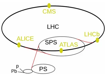
The two larger experiments, ATLAS and CMS, are based on general-purpose detectors and are designed to carry out the broadest range of physics studies possible. The two medium-sized experiments, ALICE and LHCb, have specialised detectors for analysing the LHC collisions in relation to specific phenomena. ATLAS, CMS, ALICE and LHCb detectors are installed in four huge underground caverns located around the beam crossing points of the LHC (see Figure 2.4 on the next page). TOTEM and LHCf experiments are smaller in size, and are positioned near the CMS detector and the ATLAS detector, respectively.
LHC operation was started for a first test beam circulation on 10 September 2008, but was stopped after just a few days into the experiment due to a severe fault in a superconducting magnet. After repairs and the addition of supplementary safety features, the new switch-on is scheduled for November 2009. However, a two-phase luminosity upgrade for the accelerator is already planned, to increase the probability of observing rare events and improve the measurement precision: the upgraded accelerator will be called Super LHC (SLHC) and will feature a luminosity increase by 2/3 for phase I,
planned for 2013, and tenfold for phase II in 2017, reaching the value of 1035 cm−2s−1
[1]. The consequently larger rate of events to be detected and the resulting larger amount of data to be handled will impact on the detectors, which will have to be upgraded as well. The requirement analysis for the FF-LYNX project focussed on the two main experiments: CMS and ATLAS, which are briefly described in the following sections.
!
!
!"#$%&$'%(%"#$!%&'!()*+,$-!./0!123!4)56!*.1/!$-+$61*$/2.,!+)1/237!89!./0!+!0$/)2$!2#$!,1/$.6!.(($,$6.2)63!2#.2!:$/$6.2$! 2#$!1)/!./0!+6)2)/!9$.*3;!<#1(#!.6$!2#$/!1/=$(2$0!1/2)!2#$!+6$.(($,$6.2)63!8>!./0!>8>!./0!41/.,,?!1/2)!2#$!*.1/!61/:7!!
%&'!)+$6.21)/!<.3!32.62$0!4)6!.!41632!2$32!9$.*!(16(5,.21)/!)/!@A!>$+2$*9$6!BAAC;!952!<.3!2#$/!
32)++$0!4$<!0.?3!,.2$6!05$!2)!.!3$D$6$!4.5,2!1/!.!35+$6()/05(21/:!*.:/$2E!.42$6!6$+.163!./0!.00121)/!
)4! 35++,$*$/2.6?! 3.4$2?! 4$.256$3;! 2#$! /$<! 256/F)/! 13! 3(#$05,$0! 4)6! G)D$*9$6! BAAH7! &)<$D$6;! .!
2<)F+#.3$!,5*1/)312?!5+:6.0$!4)6!2#$!.(($,$6.2)6!13!.,6$.0?!+,.//$0;!2)!1/(6$.3$!2#$!+6)9.91,12?!)4!
)93$6D1/:! 6.6$! $D$/23! ./0! 1*+6)D$! 2#$! *$.356$*$/2! +6$(131)/I! 2#$! 5+:6.0$0! .(($,$6.2)6! <1,,! 9$!
(.,,$0! >5+$6! %&'! J>%&'K! ./0! <1,,! #.D$! .! ,5*1/)312?! 1/(6$.3$! 9?! .! 4.(2)6! )4! BLM! 4)6! +#.3$! N;!
+,.//$0! 4)6! BA@M;! ./0! 9?! .! 4.(2)6! )4! @A! 4)6! +#.3$! NN! 1/! BA@O;! 6$.(#1/:! 2#$! D.,5$! )4! @A
MP! (*
B! 3
F@!
Q6$D/I! 6$4$6$/($RS7! "#$! ()/3$T5$/2,?! ,.6:$6! 6.2$! )4! $D$/23! 2)! 9$! 0$2$(2$0! ./0! 2#$! 6$35,21/:! ,.6:$6!
.*)5/2!)4!0.2.!2)!9$!#./0,$0!!<1,,!1*+.(2!2#$!0$2$(2)63;!<#1(#!<1,,!#.D$!2)!9$!5+:6.0$0!.3!<$,,7!
"#$! <)6U! )4! 6$T516$*$/2! ./.,?313! 1/310$! 2#$! VVF%WGX! +6)=$(2! 4)(53$0! )/! 2#$! 2<)! *.1/!
$-+$61*$/23!.2!%&'I!'Y>!./0!Z"%Z>;!2#.2!.6$!961$4,?!0$3(619$0!1/!2#$!4),,)<1/:!3$(21)/37!!
&$&$)$& *+,%
!
"#$!')*+.(2!Y5)/!>),$/)10!J'Y>K!$-+$61*$/2!53$3!.!:$/$6.,F+56+)3$!0$2$(2)6!2)!1/D$321:.2$!.!
<10$! 6./:$! )4! +#?31(3;! 1/(,501/:! 2#$! 3$.6(#! 4)6! 2#$! &1::3! 9)3)/;! $-26.! 01*$/31)/3;! ./0!
35+$63?**$261(! +.621(,$37! N2! 13! ,)(.2$0! 1/! ./! 5/0$6:6)5/0! (.D$6/! .2! '$33?! 1/! V6./($;! (,)3$! 2)! 2#$!
><133!9)60$6!./0![$/$D.7!!
"#$!$-+$61*$/2.,!.++.6.253!13!B@!*!,)/:;!@P!*!<10$!./0!@P!*!#1:#;!./0!()*+613$3!0144$6$/2!U1/03!
)4!0$2$(2)63!,.10!)52!1/!()/($/261(!,.?$63!.6)5/0!2#$!9$.*!+1+$;!<#$6$!2#$!(),,131)/!+)1/2!13!,)(.2$0!
JV1:7!@7\K7!V6)*!2#$!1/2$6.(21)/!+)1/2!2)!2#$!)52310$;!2#$3$!0$2$(2)63!.6$I!
F 2#$!!"#$%&";!.!31,1()/!0$2$(2)6!2#.2!6$D$.,3!2#$!26.=$(2)61$3!)4!(#.6:$0!+.621(,$3E!
F 2#$!&'&$!"()#*+&!,$-$#'(",)&!&"!J]'Z%K;!*.0$!5+!)4!.!,$.0!25/:32.2$!3$/3)63!2#.2!*$.356$!2#$!
$/$6:1$3!)4!$,$(26)/3!./0!+#)2)/3E!
F 2#$! .#/"(+,$- $#'(",)&!&"! J&'Z%K;! 2#.2! #.3! 2#$! 2.3U! )4! *$.3561/:! 2#$! $/$6:?! )4! #.06)/3!
+6)05($0! 1/! $.(#! $D$/2I! 12! 13! ()*+)3$0! )4! .,2$6/.21/:! ,.?$63! )4! .93)691/:! *.2$61.,3! ./0!
4,5)6$3($/2!^3(1/21,,.2)6_!*.2$61.,3E!
F 2#$!)0(+-$.#)1&"2;!4)6!2#$!0$2$(21)/!)4!*5)/37!
"#$! 0$2$(21/:! 0$D1($3! .6$! $/(,)3$0! 1/310$! .! #5:$! 3),$/)10! *.:/$2! 2#.2! #.3! 2#$! 4)6*! )4! .!
(?,1/061(.,!()1,!)4!35+$6()/05(21/:!(.9,$!./0!:$/$6.2$3!.!*.:/$21(!41$,0!)4!\!"$3,.7!"#$!*.:/$21(!
41$,0!13!()/41/$0!9?!.!32$$,!`?)U$`!2#.2!4)6*3!2#$!95,U!)4!2#$!0$2$(2)6`3!<$1:#2!)4!@BPAA!2)/37!Z3!1/!
*)32! &]8! $-+$61*$/2;! 2#$! *.:/$2! 13! ./! $33$/21.,! +.62! )4! 2#$! $-+$61*$/2.,! .++.6.253;! 31/($! 2#$!
9$/01/:! )4! 2#$! +.621(,$! 26.=$(2)6?! 1/! 2#$! *.:/$21(! 41$,0! .,,)<3! 2)! *$.356$! 2#$! *)*$/25*! )4! .!
+.621(,$!9?!26.(1/:!)4!123!+.2#7!!
!
Figure 2.4: The LHC ring and its four main experiment locations. Pb and p denote the linear accelerators that generate the ion and proton beams, which are then injected into the pre-accelerators PS and SPS and finally into the main ring. 2.1.2.1 The CMS experiment
The Compact Muon Solenoid (CMS) experiment employs a general-purpose detector in a broad range of physics endeavours, including the quests for the Higgs boson, extra di-mensions, and supersymmetric particles. It is located in a cavern beneath Cessy, France, close to the Swiss border and Geneva.
The experimental apparatus is 21 m long, 15 m wide and 15 m high, and comprises different kinds of detectors laid out in concentric layers around the beam pipe, where the collision point is located (see Figure 2.5). From the interaction point to the outside, these detectors are:
• the tracker, a silicon detector that reveals the trajectories of charged particles, • the electromagnetic calorimeter (ECAL), made up of lead tungstate sensors to
measure the energy of electrons and photons,
• the hadronic calorimeter (HCAL), tasked with measuring the energy of hadrons produced in each event and composed of alternating layers of absorbing materials and fluorescent scintillator materials,
• the muon chambers, for the detection of muons.
The detecting devices are enclosed in a huge solenoid magnet in the form of a cylindrical coil of superconducting cable generating a magnetic field of 4 tesla. This magnetic field is confined into a massive steel “yoke”, which accounts for the lion’s share in the total equipment weight of 12500 tons. As in most HEP experiments, the magnet is an essential part of the experimental apparatus, since the bending of a particle’s trajectory in the magnetic field allows to measure the momentum of a particle by tracing its path.
! ! !"#$%&$'%(%"#$!$%&$'()$*+,-!,&&,',+./!01!2345! ! 6+!1.--!0&$',+(0*7!,80.+!0*$!8(--(0*!&'0+0*9&'0+0*!(*+$',:+(0*/!;(--!+,<$!&-,:$!$=$'>!/$:0*?!(*/(?$! +#$!234!?$+$:+0'5!"0!,--0;!?,+,!/+0',@$!,*?!&'0:$//(*@7!+#$!$=$*+!',+$!)./+!8$!?',/+(:,-->!'$?.:$?! /$-$:+(*@!0*->!+#$!&0+$*+(,-->!(*+$'$/+(*@!$=$*+/A!+#(/!+,/<!(/!&$'10')$?!8>!+#$!+'(@@$'!/>/+$)7!+#,+! :,''($/!0.+!+#$!'$?.:+(0*!(*!+;0!/+$&/!:,--$?!B$=$-9C!"'(@@$'!DBC"E!,*?!F(@#9B$=$-!"'(@@$'!DFB"E5! "#$!B$=$-9C!"'(@@$'!:0*/(/+/!01!:./+0)9?$/(@*$?!$-$:+'0*(:/!+#,+!./$!:0,'/$->!/$@)$*+$?!?,+,!1'0)! +#$!:,-0'()$+$'/!,*?!+#$!).0*!/>/+$)7!;#(-$!#0-?(*@!+#$!#(@#9'$/0-.+(0*!?,+,!(*!&(&$-(*$?!)$)0'($/! (*!+#$!1'0*+9$*?!$-$:+'0*(:/G!+#$!BC"!:,-:.-,+(0*!(/!:,''($?!0.+!(*!,80.+!C!!/7!,*?!'$?.:$/!+#$!$=$*+! ',+$!1'0)!+#$!0'(@(*,-!C!HFI!+0!/0)$!+$*/!01!<FIA!+#$!?$/(@*!0.+&.+!',+$!-()(+!01!+#$!BC!+'(@@$'!(/! CJJ!<FI5!"#$!'$,?0.+!?,+,!01!$=$*+/!+#,+!&,//!+#$!BC"!1(-+$'!,'$!/$*+!(/!/$*+!0=$'!1(8$'90&+(:!-(*</!+0! +#$! F(@#! B$=$-! "'(@@$'7! ;#(:#! (/! ,! /01+;,'$! />/+$)! ()&-$)$*+$?! (*! ,! 1,')! 01! :0))$':(,-! &'0:$//0'/5!"#$!FB"!#,/!,::$//!+0!+#$!:0)&-$+$!'$,?90.+!?,+,!,*?!:,*!+#$'$10'$!&$'10')!:0)&-$%! :,-:.-,+(0*/!+0!/$-$:+!/&$:(,-->!(*+$'$/+(*@!$=$*+/7!+#./!'$?.:(*@!+#$!$=$*+!',+$!+0!+#$!1(*,-!=,-.$!01! ,80.+!CJJ!&$'!/$:0*?5! ! K0'! '$L.('$)$*+! ,*,->/(/! 0.'! ,++$*+(0*! 10:./$?! 0*! +#$! 234! +',:<$'! />/+$)7! +#,+! (/! +#$! ?$+$:+0'! ;(+#!#(@#$/+!?,+,!1-0;!',+$/!8$(*@!+#$!(**$')0/+!-,>$'!01!+#$!234!,&&,',+./5!"#$!+',:<$'!(/!),?$!.&! 01!+;0!/.89/>/+$)/A!,!!"#$%&'$($)(*+7!;(+#!+#'$$!:>-(*?'(:,-!-,>$'/!-0:,+$?!(*!+#$!:$*+',-!/$:+(0*!01! +#$!234!?$+$:+0'!,'0.*?!+#$!8$,)!&(&$!D+#$!/0!:,--$?!,-++$%E7!,+!',?((!8$+;$$*!M5M!:)!,*?!CJ5N!:)G! ,*?!,!."%")*/&.(+"!&(+-)0$+!;(+#!CJ!8,''$-!?$+$:+(0*!-,>$'/!$%+$*?(*@!0.+;,'?/!+0!,!',?(./!01!C5C!)5! O,:#!/>/+$)!(/!:0)&-$+$?!8>!$*?:,&/!;#(:#!:0*/(/+! 01!N!?(/</!(*!+#$!&(%$-! ?$+$:+0'!,*?!P!&-./!Q! ?(/</!(*!+#$!/+'(&!+',:<$'!0*!$,:#!/(?$!01!+#$!8,''$-5!
"#$! &(%$-! ?$+$:+0'! (/! ),?$! .&! 01! /$=$',-! /(-(:0*! /$*/0'! &-,+$/7! /$@)$*+$?! (*! CRJ! !)!x!CRJ! !)! /$*/(+(=$!$-$)$*+/!D+#$!&(%$-/EA!$,:#!&(%$-!:0*/(/+/!(*!,!'$=$'/$98(,/$?!&9*!S.*:+(0*7!+#,+!'$=$,-/!+#$! &,//,@$! 01! :#,'@$?! &,'+(:-$/! 8>! @$*$',+(*@! ,*! $-$:+'(:! :.''$*+5! "#$! /$*/0'! /(@*,-! (/! :0--$:+$?! ,*?! #,*?-$?!8>!,!/(-(:0*!T$,?9U.+!2#(&/!DTU2E7!8.)&980*?$?!+0!+#$!&(%$-!/$*/0'!DK(@5!C5RE5!!
!
Figure 2.5: the CMS experimental apparatus
When functioning at peak level, about one billion proton-proton interactions will take place every second inside the CMS detector. To allow data storage and processing, the event rate must be drastically reduced by selecting only the potentially relevant events: this task is performed by the trigger system, which carries out a two-tiered filtering, called Level-1 Trigger (L1T) and High-Level Trigger (HLT). The Level-1 Trigger consists of custom-designed electronics that use coarsely segmented data from the calorimeters and the muon system, while holding the high-resolution data in pipelined memories in the front-end electronics; the L1T calculation takes about 1 μs, and reduces the event rate from the original 1 GHz to some tens of kHz: the output rate limit of the L1 trigger is by design 100 kHz. The readout data of events which make it past the L1T filter is piped over optical links to the High Level Trigger, which is a software system implemented with a cluster of standard processors. The HLT has access to the complete read-out data and can therefore perform complex calculations to select the actually interesting events, therefore reducing the event rate to the final value of about 100 Hz.
For the requirements analysis of the FF-LYNX project, our attention focussed on the CMS tracker system, that is the detector with the highest data flow rate, being the innermost layer of the CMS apparatus. The tracker is made up of two subsystems: a pixel detector, with three cylindrical layers located in the central section of the CMS detector around the beam pipe (the so called barrel), at radii between 4.4 cm and 10.2 cm; and a silicon strip tracker with 10 barrel detection layers extending outwards to a radius of 1.1 m. Each system is completed by endcaps which consist of 2 disks in the pixel detector and 3 plus 9 disks in the strip tracker on each side of the barrel.
!
!
!"#$%&$'%(%"#$%&#%$'!()!*!+,"!-./'0!1'#'&#($2!
!
3*&4! 5'65($! 70*#'! .5! 8(%6#'9! (6! *! 8(9%0':! #(;'#4'$! <.#4! =>+5! *69! *! 7$.6#'9! ?(*$9! #4*#! 4(5#5!
&.$&%.#5! )($! 8(6.#($.6;! @(0#*;':! &%$$'6#! *69! #'87'$*#%$':! )($! &0(&A! 5B6&4$(6.C*#.(6! *69! #$.;;'$!
9'&(9.6;:!)($!&(6&'6#$*#.6;!9*#*!#(!?'!5'6#!#(!#4'!$'8(#'!1DE!5B5#'82!1*#*!#$*658.55.(6!.5!8*9'!
(6!'0'&#$.&*0!0.6A5!)$(8!'*&4!8(9%0'!#(!'0'&#$(F(7#.&!&(6@'$5.(6!%6.#5!G3>+H!#4*#!*$'!0(&*#'9!*#!#4'!
'69!()!#4'!?*$$'0:!*69!(6!(7#.&*0!0.6A5!)$(8!3>+5!#(!#4'!$'8(#'!9*#*!;*#4'$.6;!5B5#'82!I4'!&'6#$*0!
II+!5B5#'8!5'695!#$.;;'$!*69!&0(&A!#4$(%;4!(7#.&*0!0.6A5!#(!9.5#$.?%#.(6!9'@.&'5:!#4*#!.6!#%$6!9'0.@'$!
#4'8!#(!)$(#F'69!8(9%0'5!#4$(%;4!'0'&#$.&*0!0.6A52!!
I4'!5#$.7!9'#'&#($!4*5!*!5#$%&#%$'!#4*#!.5!5.8.0*$!#(!#4'!7./'0!9'#'&#($:!?%#!#4'!5.0.&(6!5'65($!70*#'5!
*$'!4'$'!5';8'6#'9!.6!#4.6!5#$.75!GJK!&8!
x
!JLK!!8!.6!#4'!.66'$!)(%$!0*B'$5:!*69!MN!&8!
x!JLK!!8!.6!
#4'!$'8*.6.6;!5./!0*B'$5H2!I4'!&4*$;'!(6!'*&4!8.&$(5#$.7!.5!$'*9!(%#!*69!*870.).'9!?B!*6!D6*0(;%'!
-.7'0.6'!O(0#*;'!GD-OMNH!&4.72!P(%$!($!5./!5%&4!&4.75!*$'!4(%5'9! <.#4.6!*!Q4B?$.9R:!<4.&4!*05(!
&(6#*.65! '0'&#$(6.&5! #(! 8(6.#($! A'B! 5'65($! .6)($8*#.(6:! 5%&4! *5! #'87'$*#%$':! *69! 7$(@.9'! #.8.6;!
.6)($8*#.(6!.6!($9'$!#(!8*#&4!Q4.#5R!<.#4!&(00.5.(652!I4'!D-OMN!5#($'5!#4'!5.;6*05!.6!*!8'8($B!)($!
5'@'$*0!8.&$(5'&(695!*69!#4'6!7$(&'55'5!#4'8!?')($'!5'69.6;!#(!*!3>+!%6.#:!)$(8!<4.&4!9*#*!*$'!
5'6#!#(!#4'!$'8(#'!1DE!5B5#'8!#4$(%;4!(7#.&*0!).?'$52!
S6! ?(#4! 7./'0! *69! 5#$.7! 9'#'&#($5:! <4'6! *! )$(6#F'69! &.$&%.#! $'&'.@'5! *! #$.;;'$! 5.;6*0! )$(8! #4'!
&'6#$*0.C'9! &(6#$(0! 5B5#'8:! #4'! 5#($'9! 5*870'5! &($$'57(69.6;! #(! #4'! #$.;;'$'9! '@'6#! *$'! 5'$.*0.C'9!
*69!5'6#!#(!#4'!&(6&'6#$*#($:!*69!)$(8!4'$'!#(!#4'!(7#.&*0!#$*658.##'$2!+%$$'6#0B!#4.5!$'*9(%#!7$(&'55!
.5!7*$#.*00B!*6*0(;T!$'*9(%#!9*#*!*$'!5#($'9!.6!)$(6#F'69!&4.75:!&(6&'6#$*#'9!*69!#$*658.##'9!#(!*!).$5#!
5#*;'!()!&(00'&#.(6!5B5#'85!.6!*6*0(;!)($8:!*69!(60B!5%?5'U%'6#0B!#4'B!*$'!9.;.#.C'9:!7$(&'55'9!*69!
#$*658.##'9! #(! #4'! $'8(#'! '0*?($*#.(6! &'6#'$2! D6*0(;! $'*9(%#! 9*#*! #$*658.55.(6! .5! 5'$.*0! *69!
5B6&4$(6(%5!<.#4!#4'!VK!,WC!XW+!&0(&A2!P($!'/*870':!*!=>+!.6!#4'!7./'0!9'#'&#($!#$*658.#5!#4'!
9*#*!$'0*#.@'!#(!*!5.6;0'!Q4.#R!G.2'2!*!7./'0!?'.6;!4.#!?B!*!7*$#.&0'H:!&(87$.5.6;!#4'!7./'0!*99$'55!*69!
#4'!4.#!*870.#%9':!.6!5./!5%&&'55.@'!VK!,WC!&0(&A!&B&0'5!<.#4!*6!*6*0(;!5.;6*0!#4*#!&*6!*55%8'!(6'!
()!Y!9.))'$'6#!0'@'05!*#!'*&4!&B&0'2!Z4'6!9.;.#.C'9:!#4'!9*#*!)($!*!7./'0!4.#!.6!*!=>+!&($$'57(69!#(!
M[! ?.#5! \]*?KN:! W+^K_`2! +(65.9'$.6;! #4'6! #4'! (&&%7*6&B:! .2'2! #4'! 7$(?*?.0.#B! )($! *! &4*66'0! #(!
;'6'$*#'! *! 5.;6.).&*6#! '@'6#! .6! &($$'57(69'6&'! #(! *! #$.;;'$! &(88*69:! #4*#! .5! &%$$'6#0B! *?(%#! N2V!
4.#5a=>+!*#!'*&4!#$.;;'$!'@'6#!\4&AJ:!$'@6`:!<'!&*6!'5#.8*#'!#4'!$'*9(%#!9*#*!$*#'!)$(8!'*&4!=>+!
.6!M[!?.#!
x
!N2V!
x
!JKK!AWC!b!JM2VM!,?.#a52!+(65.9'$.6;!#4'6!#4'!(&&%7*6&B!)($!*!JYF=>+!8(9%0':!
#4*#!.5!*$(%69!Y2N!4.#!=>+5!7'$!8(9%0'!\4&AJ:!$'@6`:!<'!4*@'!*!9*#*!$*#'!)$(8!'*&4!8(9%0'!#4*#!.5!
'5#.8*?0'!*5!Y2N!
x
!JM2VM!,?.#a5!b!LK2c[!,?.#a52!!
I4'!*6*0(;!$'*9(%#!5&4'8'!<*5!&4(5'6!8*.60B!)($!$'5(0%#.(6!$'*5(65:!5.6&'!#4'!*@*.0*?.0.#B!()!*6!
*6*0(;! 8'*5%$'! ()! 4.#! *870.#%9'5! .6! 7./'0! *69! 5#$.75! 7'$8.#5:! .6! &*5'! ()! &4*$;'! 54*$.6;! ?'#<''6!
*9d*&'6#! 5'65($! '0'8'6#5:! .6#'$7(0*#.(6! #'&46.U%'5! #4*#! .6! #%$6! .6&$'*5'! 7(5.#.(6! $'5(0%#.(6! \+,"!
I1=:! $'@6`2! W(<'@'$:! .6! $'*0! (7'$*#.(6! #4'! *6*0(;! $'*9(%#! 7$(@'9! #(! 4*@'! %65*#.5)*&#($B!
Figure 2.6: structure of a CMS pixel detector
x 150 μm sensitive elements (the actual pixels). Each pixel consists of a reverse-biased p-n junction, which reacts to the passage of charged particles by generating an electric current. The sensor signal is collected and handled by silicon Read-Out Chips (ROC), bump-bonded to the pixel sensor (see Figure 2.6).
Each sensor plate is mounted on a module, together with the ROCs and a printed board that hosts circuits with manifold tasks: monitoring voltage, current and temper-ature, synchronising clocks, decoding triggers and concentrating the data destined for the remote DAQ system. Data runs on electrical links from each module to electro-optic conversion units (EOC) that are located at the end of the barrel and on optical links from the EOCs to the remote data gathering system. The central TTC system sends trigger and clock through optical links to distribution devices, that in turn deliver them to front-end modules through electrical links.
The strip detector has a structure similar to that of the pixel detector, but the silicon sensor plates are here segmented in thin strips (10 cm x 180 μm in the inner four layers and 25 cm x 180 μm in the remaining six layers). The charge on each microstrip is read out and amplified by an Analogue Pipeline Voltage (APV25) chip. Four or six such chips are housed within a hybrid module, which also contains electronics to monitor key sensor information, such as temperature, and provide timing information in order to match “hits” with collisions. The APV25 stores the signals in a memory for several microseconds and then processes them before they are sent to a EOC unit, from which they get to the remote DAQ system through optical fibres.
In both pixel and strip detectors, when a front-end circuit receives a trigger signal from the centralised control system, the stored samples corresponding to the requested event are sent to the concentrator, and from there to the optical transmitter. Currently this readout process is partially analog: readout data is stored in front-end chips, con-centrated and transmitted to a first stage of collection systems in analog form, and only
subsequently they are digitised, processed and transmitted to the remote elaboration centre. Analog readout data transmission is serial and synchronous with the 40 MHz LHC clock. For example, a ROC in the pixel detector transmits the data relative to a single “hit” (i.e. a pixel being hit by a particle), comprising the pixel address and the hit amplitude, in six successive 40 MHz clock cycles with a 6-level analog signal. When digitised, the data for a pixel hit in a ROC correspond to 23 bits [5, 6]. Considering the occupancy, i.e. the probability for a channel to generate a significant event in cor-respondence to a trigger command, that is currently about 5.4 hits/ROC at each trigger event [6], we can estimate the readout data rate from each ROC in 23 bit x 5.4 x 100 kHz = 12.42 Mbit/s. Considering then the occupancy for a 16-ROC module [6], that is around 6.5 ROCs being hit per module, we can evaluate the data rate from each module as 6.5 x 12.42 Mbit/s = 80.73 Mbit/s.
The analog readout scheme was chosen mainly for resolution reasons, since the avail-ability of an analog measure of hit amplitudes in pixel and strips permits, in case of charge sharing between adjacent sensor elements, interpolation techniques that in turn increase position resolution [9]. The main disadvantages of this approach, which are so hindering that CMS is in need to abandon it completely in favour of a fully digital solu-tion, is that the signal is extremely prone to degradation throughout the readout chain and the analog-optical converters are highly sensitive to temperature variations [10]. The need for higher transmission speeds to handle the greater data rates resulting from the Phase I luminosity increase are another reason for the obsolescence of the current readout scheme. Considering again the case of the CMS pixel detector, for the phase I upgrade an increase factor of about 3 is foreseen for data rates from ROCs and from modules [6], calling for 160 Mbit/s links from the ROCs to the data concentrator in the module and 320 Mbit/s links from the module to the EOC unit. Similar requirements will show up for the strip detector.
2.1.2.2 The ATLAS experiment
Located in a cavern beneath Meyrn, near Geneva, ATLAS is the other general-purpose detector at the LHC. It pursues the same objectives as CMS and records similar sets of measurements on the particles created in the collisions: their path, energy, and their identity. However, the two experiments have adopted different technical solutions and designs for the magnet systems in their detectors. The comparison of the results of the two experiments will be important for cross-confirmation in case of new discoveries.
The experimental apparatus is 46 m long, 25 m high and 25 m wide and is based, sim-ilarly to CMS, on a large superconductive magnet generating a magnetic field of 2 Tesla. Integrated into the magnet, the following layers of detectors are laid out concentrically around the beam pipe (see 2.7 on the next page), listed here ordered from the innermost on:
• the inner tracker, measuring the momentum of each charged particle,
• the electromagnetic and hadronic calorimeters, measuring the energy carried by the particles,
2 The FF-LYNX project 1!"".*0%*3'(.,"*03"*,'2"#*.'0'*#'0"*03'0*?+,,*#"1/,0*$#%&*,/&+(%1+0-*+()#"'1">*.+)0'0"1*03"*1?+0)3*0%*'* $/,,-*.+2+0',*#"'.%/0*1)3"&"*$%#*03"*@6A*/!2#'.">*',#"'.-*+(*!3'1"*B<*A%(1+."#+(2*'2'+(*03"*)'1"*%$* 03"*ACD*!+E",*."0")0%#>*$%#*03"*!3'1"*B*/!2#'."*'(*+()#"'1"*$')0%#*%$*'F%/0*G*+1*$%#"1""(*$%#*.'0'* #'0"1*$#%&*87A1*'(.*$#%&*&%./,"1*53)HI>*#"4(;>*,"'.+(2*0%*$%#"1""*'*IJ9*CF+0K1*.+2+0',*,+(H*$#%&* "')3*87A*0%*03"*.'0'*)%()"(0#'0%#*+(*03"*&%./,">*'(.*'*GL9*CF+0K1*.+2+0',*,+(H*$#%&*"')3*&%./,"*0%* 03"*M7A*/(+0*56AN9:;<*D+&+,'#*#"O/+#"&"(01*?+,,*13%?*/!*$%#*03"*10#+!*."0")0%#<* !"!"#"# $%&$'( * P=@PD*+1*03"*%03"#*2"("#',Q!/#!%1"*."0")0%#*'0*03"*@6AR*+0*+1*,%)'0".*+(*'(*/(."#2#%/(.*)'4"#(*'0* C"-#(>*("'#*S"("4'<*B0*3'1*03"*1'&"*!3-1+)1*2%',1*'1*ACD>*#")%#.+(2*1+&+,'#*1"01*%$*&"'1/#"&"(01* %(*03"*!'#0+),"1*)#"'0".*+(*03"*)%,,+1+%(1T*03"+#*!'031>*"("#2+"1>*'(.*03"+#*+."(0+0+"1R*3%?"4"#>*03"*0?%* "E!"#+&"(01* 3'4"* '.%!0".* .+$$"#"(0* 0")3(+)',* 1%,/0+%(1* '(.* ."1+2(1* $%#* 03"+#* ."0")0%#1U* &'2("0* 1-10"&1<* =3"* )%&!'#+1%(* %$* 03"* #"1/,01* %$* 03"* 0?%* "E!"#+&"(01* ?+,,* F"* +&!%#0'(0* $%#* )#%11Q )%($+#&'0+%(*%$*("?*.+1)%4"#+"1<*
=3"* "E!"#+&"(0',* '!!'#'0/1* +1* VJ* &* ,%(2>* LW* &* 3+23* '(.* LW* &* ?+."* '(.* +1* F'1".>* 1+&+,'#,-* 0%* ACD>*%(*'*,'#2"*1/!"#)%(./)0+4"*&'2("0*2"("#'0+(2*'*&'2("0+)*$+",.*%$*L*="1,'<*B(0"2#'0".*?+03*03"* &'2("0>*03"*$%,,%?+(2*)%()"(0#+)*,'-"#1*%$*."0")0%#1*'#"*.+1!,')".*'#%/(.*03"*F"'&*!+!"*XY+2<*I<JZ>* ,+10".*3"#"*$#%&*03"*+(0"#')0+%(*!%+(0*0%*03"*%/01+."T*
Q 03"*!""#$%&$'()#$>*03'0*&"'1/#"1*03"*&%&"(0/&*%$*"')3*)3'#2".*!'#0+),"R*
Q 03"% #*#(&$+,'-"#&!(% '".% /'.$+"!(% ('*+$!,#&#$0>* 03'0* &"'1/#"* 03"* "("#2+"1* )'##+".* F-* 03"* !'#0+),"1R* Q 03"*,1+"%02#(&$+,#&#$>*03'0*+."(0+$+"1*'(.*&"'1/#"1*&/%(1<* * * * )*+"(!",(-(=3"*P=@PD*."0")0%#<* *
=3"* +(("#* 0#')H"#* +1* &'."* /!* %$* 03#""* !'#01T* 03"* [+E",* \"0")0%#>* 03"* D"&+QA%(./)0%#* =#')H"#* XDA=Z*'(.*03"*=#'(1+0+%(*8'.+'0+%(*=#')H"#*X=8=Z<*=3"*[+E",*\"0")0%#*+1*03"*+(("#&%10*!'#0*%$*03"* ."0")0%#>* '(.* )%(1+101* %$* LW9* ]&* 03+)H* 1+,+)%(* 1"(1%#1* .+4+.".* +(* W9* !&*x!V99* !&* !+E",1* '(.* .+10#+F/0".* +(* &%./,"1R* "')3* &%./,"* )%(0'+(1* IJ*#"'.%/0* )3+!1* '(.* %03"#* ",")0#%(+)* )%&!%("(01<* =3"*DA=*+1*03"*&+..,"*)%&!%("(0*%$*03"*+(("#*."0")0%#T*+0*+1*1+&+,'#*+(*)%()"!0*'(.*$/()0+%(*0%*03"* [+E",* \"0")0%#* F/0* ?+03* ,%(2>* ('##%?* 1+,+)%(* 10#+!1* X^9* !&*x!IL<J* )&Z* #'03"#* 03'(* 1&',,* !+E",1>* &'H+(2* )%4"#'2"* %$* '* ,'#2"#* '#"'* !#')0+)',<* =3"* =8=>* 03"* %/0"#&%10* )%&!%("(0* %$* 03"* +(("#*
12
Figure 2.7: the ATLAS detector
• the muon spectrometer, identifying muons and measuring their parameters. The inner tracker is made up of three parts: the Pixel Detector, the Semi-Conductor Tracker (SCT) and the Transition Radiation Tracker (TRT). The Pixel Detector is the innermost part of the detector, and consists of 250 µm-thick silicon sensors divided into 50 μm x 400 μm pixels and distributed in modules. Each module contains 16 readout chips and other electronic components. The SCT is the middle component of the inner detector: it is similar in concept and function to the Pixel Detector but with long, narrow silicon strips (80 μm x 12.6 cm) rather than small pixels, making coverage of a larger area wieldy. The TRT, the outermost component of the inner detector, is a combination of a “straw” tracker and a transition radiation detector. The detecting elements are drift tubes (straws), filled with gas that becomes ionised when a charged particle travels through. Between the straws, materials with widely varying indices of refraction cause ultrarelativistic charged particles to produce transition radiation and leave much stronger signals in some straws.
The raw data rate is pegged at approximately 25 Mbytes per event, which multiplied by 40 million beam crossings per second gives a total of 1 petabyte per second of raw data. The two-tiered trigger system performs a real time filtering action to select the most interesting events to retain for further analyses. The first-level (LVL1) trigger works on a subset of the information from the calorimeter and muon detectors. The decision making process takes about 2 μs, including the propagation delays on cables between the detector and the underground counting room where the trigger logic is housed. All of the information has to be kept in pipeline memories in the peripheric detectors until the LVL1 decision has been propagated to them. After the first-level trigger, the event set is reduced to about 100,000 events per second. The LVL2 trigger refines the selection of candidate objects, using fine- grained information from all the detectors, including the inner tracker which is not used at LVL1. This way, the event rate can be further reduced to about 1 kHz.
done with modalities and features that are similar to the ones in the CMS detector, and therefore also the requirements of data transmission systems about speed, radiation hardness, material budget and so on are similar, and will be similar for the LHC upgrade.
2.1.3 Common features in DAQ/TTC systems for HEP experiments
As shown in the preceding sections, despite all the possible differences in employed equip-ment and studied phenomena, all the High Energy Physics experiequip-ments share basic ar-chitectures and operating principles, and have similar features for the DAQ and TTC systems. And, moreover, in the near future the situation is not going to change. These features, as part of the FF-LYNX preliminary study, have been identified in:
• Data readout. The data readout encompasses all the nodes and links in the data transfer chain that starts from the peripheric front-end electronics and ends into the remote counting room. This path is typically called uplink and data starts to flow along it when a triggers commands so. The links that operate the transmission of readout data must provide a bandwidth adequate to the expected data rate, in order to minimise data losses due to buffer overflows and link congestions. Usually data from different readout circuits are then multiplexed into a data concentrator node, to allow their transmission onto only one or two high-bandwidth links, so that the number of cables is reduced (lowering the material budget). The required link speed commonly ranges from 40 Mbit/s to 160 Mbit/s for the links between single readout chips to their data concentrator inside a module, and from 160 Mbit/s to about one Gbit/s for the links departing from each module. Packets of readout data must also be timestamped to relate them to the trigger which sparked them. The attached timing information is used later in the readout chain in the so-called event building, a process with which all the data with the same timestamp is aggregated, so that the physical phenomenon sensed by the detector can be reconstructed. • Trigger mechanism. Triggers are fired from the central elaboration system and
run the downlink route to the front-end circuits. They have two fundamental requisites:
– the number of lost triggers due to transmission errors or other malfunctions must be minimum (possibly zero), and
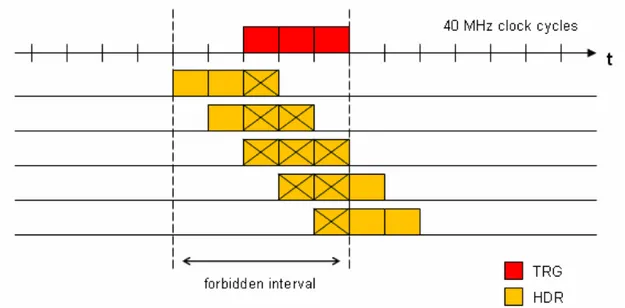
– the time it takes for a trigger to arrive at each front-end circuit (called latency) must be constant and known, in order for the timestamping of the readout data to be correct, or else the events cannot be accurately reconstructed. The trigger transmission mechanism shall grant high priority (or even dedicated lines) to trigger data and employ error protection schemes. At the same time, it shall not burden the links with so much overhead that the pace of trigger transmis-sion is slowed down. For example, the shortest interval between two consecutive triggers in the CMS and ATLAS experiments is respectively 3 and 5 cycles of the 40 MHz clock [11, 13].
In the uplink the trigger data (i.e. the information from a detector subset used for trigger calculation) is transmitted. The requirements here are fixed latency and high bandwidth. For example, in the CMS upgrade it is foreseen that data from the microstrip tracker will participate in the L1 trigger generation, with expected data rates in the range of 40-120 Mbit/s from each FE ASIC and up to 1 Gbit/s from each module [14].
• Timing and control mechanism. The master clock of the experiment (e.g. the 40 MHz accelerator clock for the LHC experiments) needs to be delivered to all Front End circuits with controlled skew, in order to synchronise the detectors with the beam crossings. The downlink has also to transmit so called “slow control” commands to control and configure Front End devices. Here the link speed re-quirements are slacker, with 40 Mbit/s being an adequate value for most cases. Currently, slow control is performed by dedicated links with custom or commer-cial protocols such as I2C [5], and a dedicated uplink is used for monitoring and response data from FE to the central control system.
• Error control. Critical data must be protected against transmission errors, that can arise from noise in the transmission lines and from Single Event Effects affecting the decision devices (e.g. photodiodes at the end of optical links). The environment of HEP experiments is particularly critical under this point of view. Transmission errors can occur in single events or in bursts, due to jets of particles hitting the lines. An error control coding scheme must be therefore adopted to limit data losses. In this respect the most critical signal is the trigger, because a lost trigger command, implies the loss of readout data associated to a potentially relevant event.
• Radiation hardness. Having to sustain years of operation in harsh radiation con-ditions, all the electronic components must be able to tolerate high level of ionising radiations (up to tens of Mrads) and the associated Total Dose and Single Event Effects without major malfunctions. Proper rad-hard circuitry shall be employed and thorough irradiation tests have to be run before actual operation.
• Material budget. The amount of non-sensor material (mechanical structures, cables, casings, cooling systems, etc.) inside the detector is a major concern in any HEP experiment, because it absorbs and deflects particles, interfering with the measurement. The material budget is usually analysed in detail for each compon-ent of the system, and for each part it is expressed as X/X0, i.e. the thickness of
the material expressed in units of its radiation length1 X
0. For data transmission
systems it is desirable to reduce the number of physical links as much as possible. This has also the secondary advantage of alleviating the problem of fitting the re-quired cables in the limited space available inside the detector. Ways to achieve this are integrating more services (timing, trigger, data transmission, etc.) in the
1
The radiation length of a material is the mean path length required to reduce the energy of relativistic charged particles by the factor1/eas they travel through matter.
same links, the use of serial instead of parallel transmission, or the concentra-tion of data streams from different sources (FE circuits) into few, high-bandwidth physical links. In some cases, the number of available cables is strictly limited by the available physical space. This poses the most stringent requirement for data transmission systems. For example, in the 2013 CMS upgrade the number of pixel modules will be increased from 784 to 1216 but there is no room for any additional fibres [6]. Therefore, CMS will need to make do with just one fibre per module, instead of the current two available for each module in the first two barrel layers. • Power dissipation. Power dissipation of electronics inside the detector is closely
related to material budget, since the more a circuit consumes, the bigger the power distribution and cooling systems have to be. Indeed, these elements play the major role in the overall material budget. As a general rule, power-hungry parts should be placed as farthest as possible from the interaction point in order to minimise the material budget in the centre of the detector. As for data transmission systems, in the current experiments typical values for the combined uplink/downlink power dissipation ranges from some mW to 20 mW for electrical links, and up to some watts for optical links [15].
2.2 Goals of the project
The FF-LYNX project was sparked by the analysis of the common features in HEP experiments, performed in close cooperation with physicists and engineers involved in the design of future detectors and Front-End electronics, and aims to define and implement an innovative data transmission system which meets the common requirements of DAQ and TTC systems for HEP experiments, offering at the same time the necessary degree of flexibility to make the system adaptable to the specific needs and conditions of the different applications. As it stands out in the previous sections, HEP experiments such as ATLAS and CMS share basic requirements and architectures. In spite of that, the two teams of physicists and engineers that developed the experiments and have been now summoned for the planned upgrades, appear in most cases to be isolated communities with little co-operation, wasting energies in finding different solutions for the same issues. Thus, a key lesson from the past ten years of activity in the design and construction of the large experiments for the LHC is that the usage of a common experiment-agnostic solution reduces efforts, resources and risks.
In particular, we spotlighted the electrical links, working toward integrating DAQ and TTC in a single solution. The development of electrical serial links, characterised by support for different speeds (from tens to hundreds of Mbit/s), low power consumption (<20mW combined) and high rad-tolerance (tens of Mrad) would allow a reduction in the number of interconnections within the detectors to shift power-hungry EOC units away from the active regions. While, at the moment, the research is thriving with prototypes of optical gigabit transmissions to be used from the EOCs to the remote DAQ room (e.g. CERN’s Gigabit Bi-directional Transceiver (GBT) and ESA’s SpaceFiber [18, 19]), in the field of hundred-megabits electrical communications from the detectors to the EOCs
still does not exist an approach which at the same time meets the necessary requirements and is flexible and universal as much as FF-LYNX is planned to be. Existing protocols specialised in configuration and control such as I2C and CAN do not fare well as far as speed is concerned (<1 Mbit/s), whereas higher-performance general-purpose proto-cols for consumer electronics, telecommunications, industrial automation, automotive or aerospace (e.g. Ethernet, Firewire, Fiberchannel, SpaceWire) all fail to meet one or more of the stringent requirements of high rad-tolerance, low power, low material budget (e.g. SpaceWire uses 8 wires), but, most importantly, fixed and known trigger latency.
FF-LynX is intended to fill the vacancy of such a HEP-oriented protocol, but its port-folio of features would also render it suitable for employment in the field of astrophysics and remote space sensing, where the ever-increasing use of CCD and CMOS pixel image sensors in detectors establishes requirements similar to those of the HEP data acquisition systems.
The proposed protocol is intended to offer these manifold key features:
• Integrated distribution of TTC signal and DAQ data. The FF-LynX pro-tocol is designed to integrate both these fundamental functionalities in just two interfaces: a universal transmitter and a universal receiver. In the downlink the transmitter would distribute TTC signals, while in the uplink the same type of transmitter would send readout data in response to triggers, monitoring data in response to commands and the high-priority constant-latency data from which the L1 trigger is generated. Likewise a single type of receiver would be able to sit at both the downlink and uplink endpoints. Furthermore, clock would travel along-side data in the same link, such that just a single wire would depart from each transmitter (low material budget).
• Availability of a high-priority command. The trigger command transmission is integrated with generic data transmission into the same link, but the protocol gives highest priority to the trigger in order to ensure its delivery to the receiver with fixed and known latency, disregarding any traffic condition on the link. • Error robustness of critical signals/commands. The trigger and other signals
which are vital for protocol operation (i.e. headers and frame descriptors) are protected against transmission errors by means of an appropriate encoding that ensures the correct recognition of the transmitted command and of its timing. • Flexibility. The FF-LYNX protocol is meant to offer a high degree of flexibility
with respect to various parameters and aspects of transmission systems, such as data rate, data format, system architecture. Regarding the data rate, the protocol is proposed in different versions with different values for the data transmission speed, which are multiples of the master clock frequency of the system (e.g. the 40 MHz clock for LHC experiments) to facilitate the generation of the transmission clock and the distribution of the master clock through the link itself. As for data format, the chosen approach is that of transparency with respect to the transported user data, i.e. the protocol does not expect the payload to conform to any particular
structure, thus freeing from the need to refactor the data in a fixed format. Finally, as far as the system architecture is concerned, the protocol is designed for a basic point-to-point application, but with few minor tweaks support is granted to the ring and star topologies, which are quite common in the detectors for HEP experiments. To that end, besides the transmitter and receiver interfaces, the development of a concentrator unit is foreseen. Such unit would aggregate data coming from different sources into a single, high-speed uplink and would broadcast TTC signals from a single downlink to multiple destinations. The data concentrator could also organise readout data on the basis of the tag attached to it (i.e. timestamp), thus performing a early stage of event building, still inside the detector.
• Compatibility with different link technologies. The FF-LYNX protocol oc-cupies the data-link layer of the ISO/OSI protocol stack and is intended to be compatible with different technologies for the implementation of the physical layer, such as standard or low power LVDS (Low Voltage Differential Signalling). As for the hardware implementation, the goal is to design and develop low-power, radiation-tolerant interfaces, targeted to a standard CMOS technology (e.g. ST or IBM, available through CMP, MOSIS and Europractice programs), and make them available to the designers of the integrated circuits for future HEP experiments as fully characterised and tested Intellectual Property (IP) cores, which will be parametric and partially config-urable. The required tolerance to Total Ionisation Dose (TID) and Single Event Effects (SEE) will be obtained by using CMOS standard technologies below 180 nm (that proved to be intrinsically robust to some TID effects, such as threshold voltage drift because of the reduced thickness of the oxide) and applying appropriate solutions at architectural, circuital and layout level (e.g. triple redundancy, hardened flip-flops). With respect to custom rad-hard technologies, this approach offers the possibility of benefitting from the high performance of standard processes (logic density, power consumption, speed, avail-ability of pre-designed library cells) while still achieving the required radiation tolerance.
2.3 Project design flow
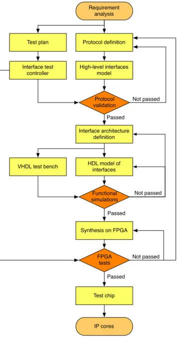
The first step of the FF-LynX project was to set up a methodology which divided the design activity in successive phases interwoven with verification steps, in order to assess whether the current stage was polished enough to move on to the next or needed further refinement. The high level model played a pivotal role in the evaluation of the defined protocol and the draft interface architecture, allowing a performance comparison of dif-ferent approaches on the basis of conveniently chosen cost functions and figures of merit (e.g. bandwidth efficiency, robustness to errors, etc.). A diagram illustrating the design flow is reported in Figure 2.8 on page 25, while here follows the description of each phase: • Protocol definition. Moving from the requirement analysis outlined in Section 2.2 on page 20, the first stage of the activity is the definition of the FF-LynX protocol in a first, tentative version to be submitted for suggestions and requests from FF-LynX collaborators (physicists and engineers involved in the design of the detectors), to
leverage their expertise in the field of HEP experiments. This first version of the protocol approaches the problem from the ISO/OSI data-link layer level and fulfils the requirements with a mix of custom and standard solutions.
• Validation in a high-level simulation environment. A high-level software simulation environment is created to model the transmitter and receiver interfaces, implementing the defined protocol. A surrounding test bench provides the stimuli and gauges the results. The chosen language is SystemC, because it offers a mix of rapid high-level prototyping and hardware-oriented modellisation (see Section 5.1 on page 63). The basic task of the high-level simulator is the evaluation of specific cost functions and figures of merit (e.g. bandwidth efficiency, data loss rate, data latency) that have been defined on the basis of system requirements. Furthermore, by evaluating these parameters, the high-level simulator also gives valuable inform-ation about hardware aspects of the interfaces, such as the optimal size for the buffers, thus providing guidelines for the definition of the hardware architecture. • Definition of the interfaces’ architecture. After the protocol validation phase,
the architecture of the hardware interfaces implementing the first version of the protocol is defined, following indications from the high-level simulation phase. The operation of the transmitter and receiver interfaces is divided into functional blocks (e.g. buffer, encoder, serialiser and so on) in order to simplify the implementation and to allow separate verification, in the following HDL simulation phase, of the correctness of each sub-function.
• VHDL modelling and simulation. After defining its architecture, a low-level model of the interfaces is created to endeavour in functional simulation and to pre-pare the ground for synthesis. Realised using a Hardware Description Language (HDL), this model is highly-parameterised to allow for quick changes to follow in-dications coming from the high-level simulator. Each block of the architecture is separately modelled and tested in a specific test bench through functional simu-lation to verify its functionality, so to progressively build a model that is verified in each and every part. Finally, the complete transmitter-receiver model is wired to a test bench that includes emulators for the transmitting and receiving hosts to verify the overall functionality of the system.
• FPGA prototyping. A phase of FPGA-based emulation is foreseen, to provide additional verification of the system functionality and to evaluate different solutions for the physical layer. The HDL models of the interfaces are synthesised on an FPGA together with the model of a surrounding test system, which provides the test vectors to the interfaces’ model and records the results. The FPGA is mounted on a development board containing all the resources required for the test, such as memory, connectors, network interfaces etc. Furthermore, by choosing an FPGA with I/O ports in multiple standards (LVDS, LVCMOS, etc.), the operation of the protocol with different link technologies can be tested. As of September 2009, the FF-LynX project has not completed this phase yet.
• Test chip. The design and realisation of a test chip is foreseen. This is the final step to complete the verification and the characterisation of the FF-LYNX interfaces. The chip will contain the transmitter and receiver interfaces (in all the different versions in terms of transmission speed) and the test bench architecture which will have been already synthesised in the FPGA emulator and will be realised in a commercial CMOS technology (below 180 nm), accessible to INFN through CMP, MOSIS or Europractice programs. The chip will be then tested in order to characterise the interfaces in terms of their electrical and thermal properties. Radiation tests will also be performed to evaluate tolerance to TID and SEE. The final goal is the creation of IP hardware macrocells, fully characterised and tested, and to make them available to designers of ASICs for future High Energy Physics experiments for integration in their systems.
Requirement analysis Protocol definition Test plan High-level interfaces model Protocol validation Interface architecture definition Not passed HDL model of interfaces Functional simulations Synthesis on FPGA FPGA tests Test chip IP cores VHDL test bench Not passed Passed Passed Passed Not passed Interface test controller