Department of Chemical Engineering Materials Environment
Electrical, Materials and Nanotechnology Engineering (EMNE)
(XXX cycle)
Ph.D. Thesis
Modified aluminide coatings
with reactive element
for turbine blades protection
Virgilio Genova
Introduction . . . ……….. 7 Chapter 1 – Gas turbojet………8
1.1 Principle of operation 1.2 Operating conditions 1.3 Desing of a turbojet 1.4 Ni-based super alloy. 1.5 Degradation phenomena
References………25
Chapter 2 – High temperature coatings………..26
2.1 Coating requirements
2.2 Protection systems for harsh environments 2.2.1 Thermal barrier coating (TBCs) 2.2.2 Bond coat: state of art
2.3 Diffusion aluminide coatings
2.4 Platinum modified aluminide coatings
2.5 Modified aluminide coatings with reactive elements 2.5.1 State of the art
References . . . .. . . ..41
Chapter 3 – Processes for production of diffusion coatings………..43
3.1 Coatings technique
3.2 Growing mechanisms of diffusion coatings 3.2.1 High temperature low activity process 3.2.2 Low temperature high activity process 3.3 Pack cementation
3.3.1 Above the pack cementation 3.4 Slurry aluminization
Chapter 4 – Design of experimental activities………54
4.1 Phase 1: oxidation and hot corrosion resistance 4.1.1 Standard aluminide caotings
4.1.2 Isothermal oxidation 4.1.3 Hot corrosion tests
4.1.4 Modified aluminide coatings with Zr 4.2 Phase 2: Electroless nickel plating
4.2.1 Principle of deposition 4.2.1 Plating solution compositions 4.2.3 Plating solution parameters
4.2.4 Selected plating solution parameters 4.2.5 Nanocomposite (Ni-nAl2O3)
4.3 Phase 3:Slurry aluminization of electroless pure nickel coatings
References . . . .78
Chapter 5 – Experimental results………..80
5.1 Phase 1: Oxidation and hot corrosion resistance
5.1.1 Samples obtained with NH4F as activator salt 5.1.2 Samples obtained with AlF3 as activator salt 5.1.3 Isothermal oxidation
5.1.4 Oxidation kinetic 5.1.5 Hot corrosion
5.1.6 Modified aluminide coating with Zr 5.1.7 Isothermal oxidation
5.1.8 Oxidation kinetic 5.1.9 Hot corrosion
5.2 Phase 2: Electroless pure nickel plating 5.2.1 Solution A
5.2.2 Solution B
5.2.3 Nanocomposite (Ni-nAl2O3)
5.3 Phase 3: Slurry aluminization of electroless pure nickel samples 5.2.1 Plating solution A
5.2.2 Plating solution B 5.2.3 Surface characterization 5.2.3 Wettability
5.4 Electroless pure nickel plating with n-Al2O3 5.5 Slurry aluminization
5.4.1 Surface characterization 5.4.2 Preliminary oxidation tests
References . . . 155
Lyst of acronyms
ATR-FTIR = Attenuated Total Reflectance Fourier Transform Infrared Spectroscopy CVD = Chemical Vapor Deposition DST = Dynamic Segregation Theory René 108DS = Directionally Solidified EDS = Energy Dispersive Spectroscopy EDTA = Ethylendiaminotethracetic acid ENL = External Nickel Layer
EPNP = Electroless Pure Nickel Plating FE-SEM = Field Emission gun Scanning Electron Microscopy
GDOES = Glow Discharge Optical Emission Spectroscopy
HPC = High Pressure Combustor HPT = High Pressure Turbine
HTHC = High Temperature Hot Corrosion HTLA = High Temperature Low Activity HRTEM = High Resolution Transmission Electron Microscopy
IDZ = Interdiffusion Zone
IPT = Intermediate Presurre Turbine LPC = Low Pressure Combustor LPT = Low Pressure Turbine
LTHA = Low Temperature High Activity LTHC = Low Temperature Hot Corrosion PN_A_ = Pure Nickel_solution A_
PN_Al_ = Pure Nickel_Aluminum_ RE = Reactive Element
SEAD = Selected Area Diffraction TBC = Thermal Barrier Coating TGO = Thermally Grown Oxide
VPA= Vapor Phase Aluminizing XRD = X-Ray Diffraction List of symbols PR = plating ratio wt % = weight percentage T = temperature h = hours
x = mass or thickness of oxide kP = parabolic contant
(g) = gas phase (l) = liquid phase (s) = solid phase ∆M = mass variation
7
INTRODUCTION
Increasing the maximum temperature of the gases introduced into the turbine increases both the efficiency and performance of a turbo-gas system; Switching from an input temperature of 900 ° C to 1250 ° C can result in a 30% increase in output power, leaving unchanged consumption. In order to ensure the structural integrity of components working in the hottest areas of the engine, research over the last decades has focused on the development of increasingly innovative technologies that aim to increase the efficiency of the system while at the same time increasing its operating life.
Turbine blades are one of the most critical components of this system because they not only work in a highly aggressive environment, but are also subject to strong mechanical stresses related to the rotation of turbochargers and aerodynamic loads. In addition to the presence of oxidation and hot corrosion mechanisms, high temperatures contribute to the degradation of the structural properties of the component and result in thermo-mechanical stress related to the temperature gradients and to the different coefficients of thermal expansion of the used materials.
In those applications where operating temperatures are compatible with the thermomechanical properties of the materials used, the turbine blades are coated to provide protection against high temperature oxidation and hot corrosion phenomena. If the operating temperatures are too high, multiple solutions are taken to reduce the temperature experienced by the component; the most important are: internal and external cooling techniques and the use of special coating systems (TBCs - Thermal Barrier Coating).
TBC coatings are a multilayer system consisting of a top ceramic layer (top coat) and an intermediate layer (bond coat) designed to protect the component from high operating temperatures and oxidation, respectively.
The aim of this work is to increase the performance of turbojet engines used in the aeronautical field, by appropriately modifying the bond coat formation processes. In order to achieve this, at the first part of this work, the change of processes already used in the industrial field was proceeded, while in the second part of the work an innovative and alternative method was proposed and studied to improve these processes.
8
CHAPTER 1
Gas Turbojet
Gas turbines have been used since 1791[1] in a wide variety of applications including aircraft propulsion, marine propulsion and power generation. Components of these engines experience very high stresses and temperatures in highly corrosive and oxidizing gases, and are required to maintain their mechanical properties for thousands of hours of service.
1.1 Principle of operation
The turbojet is a turbogas-based aeronautical propulsion. Figure 1.1 shows a section of a simple turbojet, where the various stages of the engine are illustrated.
Figure 1.1: Cross-section of a simple turbojet
The dynamic intake moves air from outside and drives it into a compressor, where it slows down and compresses. The compressed air then enters in the combustion chamber at a pressure of about 30 ÷ 35 bar and at a temperature around 550 ÷ 625 ˚C. Combustion takes place here, with fuel injection in the compressed air stream. At this point, hot combustion gases are forced into the turbine, expanding them and having the role of providing the power needed to move the compressor. At the exit of this stage the gas is still at a higher pressure than the ambient
temperature, and can therefore be accelerated in a nozzle. In this way, the propulsion fluid is ejected at a higher speed than the one with which it enters the engine, thus generating the thrust.
The excellent properties in terms of thrust, specific consumption, thrust / weight ratio, have imposed this family of propulsion as the most widely used in civil aviation as well as military.
9 The jet engine based on the gas turbine cycle was first patented by Frank Whittle in Great Britain in 1930, but only in 1939 was the first aircraft propelled by a turbojet. After the end of the Second World War it was established thanks to its high specific thrust (per unit weight of the engine) and the low-power specific at high speeds.
The simple turbojet is extremely efficient at high subsonic flight speeds. To extend the field of application of the turbojets and to improve their efficiency throughout the subsonic field, the turbofan was introduced, as shown in Figure 1.2
Figure 1.2: Turbofan Pratt & Whitney PW4000
1.2 Operating condition
Figure 1.3 shows a section of the Rolls-Royce Trent 800 reaction engine (Boeing 777 aircraft engine), and illustrates the various phases and pressure and temperature profiles along the engine, while Table 1.1 summarizes the operating conditions of each section:
10
Figure 1.3: Section of the Rolls-Royce Trent 800 engine with temperature and pressure profile for the different
stages[2]
Table 1.1: Operating parameters for Rolls-Royce Trent 800
Components Material Pressure [bar] Temperature [°C] Rotation speed [rpm] FAN Titanium 1 810 3500 LPC Titanium 8 290 6800 HPC Titanium 37 600 10200 COMBUSTOR Ni-alloy 35 1500 - HPT Ni-alloy 35 1400 10200 LPT Ni-alloy 14 900 6800 EXHAUST Ni-alloy 6 860 3500
11 As can be seen from Table 1.1, the operating temperatures to which the various components are subjected are several, and this directly affects the choice of materials in the different engine sections (Figure 1.4)
Figure 1.4: Materials used in a Rolls-Royce Trent 800
Finally, Table 1.1 also shows how high pressure turbine blades (HPTs) are the components
operating in the most severe conditions in terms of temperature and pressure. They also experience high tension due to centrifugal forces, constant over time and rapid thermal transients during the flight cycle.
1.3 Design of a turbojet
The criterion on which the choice of materials is based is, once resistance specifications have been achieved, the performance improvement in terms of internal speed and temperature reached by the gas, while maintaining the entire lightweight system.
As mentioned in Section 1.2, the turbine is the most critical part of an aeronautical engine; For this reason, over the years, research has focused particularly on the study of materials that meet certain thermal and mechanical resistance requirements at high temperatures. From here on, attention will be focused on turbine blades, as it is the resistance to the thermal and mechanical stresses of these components that discriminates the maximum permissible temperature in the combustion chamber and consequently the performance of the entire engine.
From a mechanical point of view, the main factors to be taken into account during design are creep and thermal and mechanical fatigue, as well as the resistance requirement to the tested loads. The first
12 two phenomena mainly affect the first stage of turbines, while for the second stage the limiting factor is mainly creep.
In addition, the hot gases that invest the blades are highly oxidizing, and contain contaminants such as chlorides and sulphates, which can cause hot corrosion of the component; these gases may also contain erosive elements [3]. Erosion can be caused by the sand during take-off and landing.
Figure 1.5 shows the temperature profile of a HPT blade. Considering the gas temperature increases at the turbine entry these values are now considerably higher, although the temperature profile essentially remains the same.
Figure 1.5: Temperature profile for a blade of High Pressure Turbine (HPT)[4]
Then, a turbine blade must have the following characteristics: 1. High mechanical resistance at high temperatures;
2. Resistance to creep, thermal fatigue and mechanical fatigue; 3. High microstructural stability;
4. Resistance to oxidation and hot corrosion; 5. Resistance to erosion.
In practice, it is not easy to collect all of these properties in a single material, and that is why superficial coatings that can meet the characteristics of the substrate are used in this kind of system.
13
1.4 Ni-based superalloy.
The word superalloy means a group of alloys developed for high performance applications at high temperatures, such as aircraft turbine engines [5].
As reported by Sims and Hegel [6], superalloy is defined as "an alloy developed for high temperature applications, generally based on elements of Group VIII-A, which have high mechanical strength and surface stability."
The superalloys can generally be divided into three classes, according to the main alloy element: 1. Nickel-based (Ni)
2. Cobalt-based (Co) 3. Iron-based (Fe)
Ni-based superalloy is the most commonly used for turbine blades manufacturing.
Figure 1.6 describes the turbine working temperature trend as a function of the materials that have been used for the realization of the turbines over the last sixty years; in particular, the monocrystalline Ni-based superalloys have been greatly developed over the last few years due to the growing demand for materials capable of delivering high mechanical performance at high temperatures. These alloys have a very high mechanical strength at high temperatures, allowing theoretical achievement of temperatures up to 1300°C without any damage. The high thermomechanical resistance is mainly due to the absence of discontinuities originating from grain boundaries and precipitate concentration sites, which in the polycrystalline superalloys represent the triggering and propagation zones of the cracks. Table 1.2 shows the characteristic temperatures at the compressor output and at the turbine intake from 1955 to the present.
14
Table 1.2: Operating temperatures in the last 60 years
Service year Temperature [°C] Outlet compressor Temperature [°C] Inlet turbine 1955 379 771 1965 427 938 1975 593 1343 1995 693 1427 2008 >700 >1500 2015 766 1760
Thanks to the availability of materials to withstand the increasing turbine gas entry temperatures, aircraft engines quadrupled (from the first Henkel turbine in 1939) their push / weight ratio with a specific consumption of approximately halved. Figure 1.7 shows the three types of superalloys used for the production of turbine blades and the improvements recorded according to the life time of each type of material as previously stated, having conventionally associated polycrystalline alloys with a value of 1.
Figure 1.7: Features of three different superalloy
Polycristalline Directionally
solidified Monocristalline
Creep Resistance
Thermomechanical
fatigue resistance Corrosion
Resistance C yc le s Polycristalline Directionally solidified Monocristalline
15 Ni-based super-alloys offer high performance:
1. High melting temperature
2. High resistance, which includes tensile strenght, creep and fatigue resistance 3. Ductility
4. Toughness
5. High temperature corrosion resistance
However, nickel does not have these properties, since pure metals, such as nickel, are generally too ductile and do not have sufficient resistance to the harsh environments, both mechanically and chemically. Therefore, these are rarely used without being reinforced by various mechanisms. Nickel-based superalloys are generally reinforced by precipitation hardening or solid-solution strengthening, both of which are effective as reinforcing methods at high temperatures.
Precipitation hardening
In the precipitation hardening, soluble atoms participate in the creation of a second fine phase and highly dispersed. Traditionally, two thermal treatments are used for Ni-based superalloys. The first is the thermal treatment to homogenize the microstructure and reduce the effects of elemental segregation. The second is the aging to develop phase precipitates g'- [Ni3(Al, Ti)]. These precipitates,
consistent with the matrix, and extremely stable in temperature, act as a barrier to the movement of the dislocations, greatly increasing the resistance to creep. Elements such as Al and Ti promote the creation of phase g', by alloying with the phase g-Ni. The size of this phase can be precisely controlled by means of thermal treatments. Generally, this type of hardening is used in turbine pallets.
Solid solution strenghtening
In this type of hardening, solute atoms (such as Al) randomly substitute solvent atoms (Ni, in this case) without altering the crystalline structure.
The continuous phase, characterized by a center-faced cubic lattice (cfc), forms the matrix of Ni-based alloys; this is hardening by the solid solution with several randomly distributed atomic species. Various metallic elements (Co, Cr, Mo, Fe, Ta, W, Re) are dissolved in the matrix by randomly replacing Ni atoms. Due to their different sizes than Ni, the solid solution causes local stresses that prevent the movement of the dislocations, interacting with the stress field caused by the dislocations themselves. In addition, solute atoms may also go to the interstices between the atoms of the matrix by anchoring the grain boundaries and thereby improving the sliding and migration resistance that would occur during the creep diffusion.
16 It is preferred to use this type of hardening in applications where high mechanical strength is required.
1.5 Degradation phenomena. Hot corrosion and oxidation at high temperature
Turbine blades, especially those in high pressure conditions (HPT), are subjected to high stresses and temperatures; according to the operating conditions, can trigger creep, hot corrosion, high temperature oxidation and surface erosion as mentioned in Section 1.4. All these aspects must necessarily be taken into consideration during the design process to ensure proper operation and useful life of the component. Figure 1.8 shows the complexity of the elemental composition of a Ni-based superalloy for aeronautical applications [7]. The complexity, in terms of chemical compositions, don’t allow to obtain a material that can have some high mechanical properties with a high resistance to harsh environments.Figure 1.8: Alloy elements present in Ni-based superalloys. The elements with lesser benefits are marked with a
cross-hatch, while the harmful elements for the performance of the material are marked with a horizontal hatch [8].
For this reason, it is simpler and more functional to use surface coatings. The idea of applying protective layers on the surface of turbine blades was practiced already in 1960 and found extensive applications. Since then, protective coatings are conventionally used for aeronautical engines and ground turbines. Corrosion phenomena can be divided into two types: uniform corrosion and localized corrosion.
Localized corrosion is particularly present at the root of the blade, exposed to temperatures around 620 to 760 ° C. These areas of damage can then expand and reach to the center of the component causing the failure. There is a close relationship between the damage and the characteristics of stresses and the environment: the higher the velocity of the flow that invests the blade, the less the
17 corrosion damage; the lower the quality of the fuel used and the more severe will be the corrosion; the longer the operating time, the more penetration depth of the corrosion products will be.
The uniform corrosion can be classified according to three different phenomena (Figure 1.11): high temperature oxidation (T> 1000 ° C); hot corrosion at high temperatures (Type I: T = 850 to 950 ° C); hot corrosion at low temperatures (Type II: T = 650 ÷ 800 ° C) [9].
Figure 1.9: Corrosion rate vs Temperature [10]
High temperature oxidation is a phenomenon where metals and alloys exposed to oxygen or a gas containing oxygen, at high temperatures, convert a part or all of the metals into their corresponding oxide.
The oxide, if it is attached to the substrate, can give rise to a degree of protection and slow down the oxidation kinetics, or may become detached, exposing the underlying substrate to oxidation; In addition, for long exposure times, the phase responsible for selective oxidation can be exhausted in the substrate and thus initiate the oxidation of a different element / phase with formation of a smaller scale oxide, resulting in a sensible acceleration of the oxidative phenomenon.
The theory of Pilling-Bedworth (1923) tried to explain why some metals form a protective scale and others do not; this theory argues that the ability to protect the scale depends on the ratio between the molar volumes of the metal and its oxide. A general indicator of the protection of the oxide scale is given by the Pilling-Bedworth ratio (PBR) defined as:
18 • PBR <1: the volume of oxide formed is less than the volume of metal consumed; porous, cracked and non-protective scale are formed;
• PBR> 1: layers of protective oxides are formed;
• PBR >> 2: the volume of oxide is much greater than the volume of the metal; so, the scale is very compressed.
However, this theory is not always verified, but there are some exceptions due to approximations that are adopted; these relate to the mechanism of oxide growth, geometry, the volatility of the oxide and the chemical effects of alloy elements. However, in general, it is a qualitative indication.
A metal is oxidized since the free energy variation ∆G0, associated with the reaction, is negative.
∆G is influenced by a number of parameters such as: • Temperature
• Partial oxygen pressure • Composition
The effect on the ∆G0 of the temperature and partial pressure of O2 at the variation of the oxidized
19
Figure 1.10: Ellingham’s diagram
Figure 1.10 shows that noble metals are at the top of the diagram, indicating that they are less reactive. The Ellingham diagram allows:
1. to order oxides according to their greater or less metal reduction reaction,
2.to determine the partial pressure of oxygen in equilibrium with a metal at a certain temperature 3. to determine the degree of CO / CO2 or H2 / H2O that cause the reduction of a metal oxide at a
20 However, Ellingham's diagram does not allow predicting the rate of oxidation reactions and therefore does not account for kinetic aspects.
It has been experimentally observed that the growth of the oxide layer follows one of the following laws:
• Linear Growth: 𝑥 = 𝑘%𝑡
• Parabolic Growth: 𝑥' =()
' 𝑡
• Logarithmic Growth: 𝑥 = 𝑘*log(𝑎𝑡 + 1)
where x is the thickness of the oxide layer after exposure time t, kL, kP and ke are growth rate indices,
temperature functions T, and a is a constant.
Linear growth
If the metal surface is not protected by an oxide scale, the oxidation rate remains constant over time. In this growth mechanism is the reaction between metal and oxygen to control the degree of oxidation at the interface between oxide and metal scales, while the species transport process is not influential. The oxidation kinetics is described by:
𝑑𝑥 𝑑𝑡 = 𝑘% 𝑥 = 𝑘%𝑡
with x mass or thickness of oxide, considered zero at the initial moment (Figure 1.11).
21 Oxidation never slows down. For sufficiently long exposure times the metal is consumed
completely.
As mentioned, this phenomenon occurs when the RPB ratio is less than 1, or if the oxide is volatile or liquid.
Parabolic Growth
Many systems oxidize by following a parabolic pattern. Oxidation in these cases is thermally activated and the rate of growth is controlled by ion diffusion through the oxide layer, with driving force caused by a chemical potential gradient. The growth rate is inversely proportional to the thickness, and kinetics are described by:
𝑑𝑥 𝑑𝑡 = 𝑘4 1 𝑥 𝑥'=𝑘4 2 𝑡
with x mass or thickness of oxide, considered zero at the initial moment (Figure 1.12).
Figure 1.12: Parabolic oxidation kinetic
As the thickness of oxide increases, the diffusion distance increases and the kinetics thus slows down.
Logarithmic growth
The oxidation rate generally follows a logarithmic or reverse logarithmic law at low temperatures (below 400 ° C) when only a thin film (<200 nm) of oxide has formed [12]. The driving force that allow the growth is the formation of localized electric fields in the vicinity of the metal surface; absorbed oxygen atoms acquire electrons from metal atoms, creating large electric fields along the thin layer between positive metal ions and negative oxygen ions. Metal atoms are driven by the electric field through the oxide layer. The oxidation kinetics in the case of logarithmic kinetics is described by:
22 𝑥 = 𝑘*log(𝑎𝑡 + 1)
in the case, instead, of inverse logarithmic kinetics we have: 1
𝑥= 𝑏 − 𝑘8log 𝑡
with x mass or thickness of oxide, considered zero at the initial moment (Figure 1.13).
Figure 1.13: Logarithmic and inverse logarithmic oxidation kinetic
The metals that oxidize with this kinetics reach a thickness of oxide which oxidation apparently stops.
When metals and alloys, in a high temperature oxidizing environment, have the surface covered with a thin film of salts, accelerated oxidation can occur. This phenomenon is referred to as hot corrosion, and affects the ability to protect the substrate by the oxide scale. This type of attack is sensitive to a different number of variables such as composition and amount of deposit, gas composition, temperature, surface erosion, composition and alloy microstructure.
It has been shown that the aggressiveness of this type of attack, which can be catastrophic, consists of two phases:
1. Initial Stage: The alloy and the deposit are subject to alteration, such as the reduction of the element favoring the formation of the protective oxide scale, the incorporation of a deposit component into the alloy, the dissolution of oxides in the salts, the formation of cracks and / or channels in the scale. During this phase the corrosion rate is slow and similar to that in the absence of the deposit;
2. Propagation Phase: The salts enter through the damaged scale and propagate to the scale-alloy interface. When the deposit reaches low oxygen sites and meets the depleted zone of element alloy that create a protective oxide scale (such as Cr and Al), propagation occurs quickly.
23 Generally, corrosion that occur above the melting point of the salts is called type I hot-corrosion, while the one that occurs below the melting point of the individual constituents of the salts, unless they form eutectic, is called type II hot corrosion.
High Temperature Hot Corrosion (HTHC) Type II
The HTHC begins with the condensation of alkaline metal salts melted on the surface of the component. A number of subsequent chemical reactions cause the attack of the protective oxide scale with an acceleration of the oxidation phenomenon and the formation of a porous oxide scale.
Mainly, during the combustion, the salt formed is Na2SO4 starting from Na and S present in the
atmosphere and in the fuel; this salt has a high thermodynamic stability. Other impurities contained in the fuel or atmosphere such as vanadium, phosphorus, lead and chlorides can be combined with sodium sulphate and form a mixture of salts with low melting temperature, thus expanding the area undergoing corrosive attack.
Potassium sulphate K2SO4 behaves in a similar way to sodium sulphate.
Vanadium is an inevitable contaminant in some fuels, especially in marine ones. In addition to its low melting point, vanadium compounds greatly increase the solubility of the oxide when mixed with Na2SO4.
This type of corrosion can generally be divided into four progressive stages, from initial start, up to component failure:
1. At the initial stage, a slight increase in surface roughness is observed, due to the growth and localized fracture of the oxide layer. However, neither the chromium impoverishment in the substrate nor the mechanical integrity loss of the component is observed;
2. At this stage, the roughness of the surface increases due to continuous breaks of the oxide layer. Chromium in the substrate begins to run out, but mechanical integrity is not affected yet;
3. The oxidation of the material reaches a considerable depth; Mechanical integrity is compromised and blades must be replaced. Also, at this stage, corrosion is able to proceed independently of the presence of sodium;
4. At this stage, the catastrophic attack of the material occurs. The failure of the component becomes very likely due to the loss of structural material.
From a macroscopic point of view, this type of corrosion is characterized by the material's peeling and significant changes in color (greenish tone resulting from the formation of NiO). Microscopically, morphology is characterized by the presence of sulphates and depleted regions under the porous, non-protective scale.
24 Figure 1.14 shows the components used in aeronautical field coated with alumina (Figure 1.14a)), subject to HTHC, which reveals the characteristics of the attack. In Figure 1.14b), sulfur attack is evident, which play an important role in the degradation process, while Figure 1.14 (c) is shown the penetration of the coating and exposure of the substrate to the attachment.
Figure 1.14: Micrographs of the microstructural evolution during hot corrosio – a) Ni-base aluminized HTHC; b-c)
cross-section microstructure, respectively, for the coating and the substrate [11]
Low Temperature Hot Corrosion (LTHC) Type I
LTHC generally occurs below the melting point of pure salts, but may also occur above the melting temperature of the salt itself if the deposits form a eutectic with a melting point far lower than that of the individual constituents. This is the case of the Na2SO4 and V2O5 compound, characterized by
a melting temperature significantly lower than the individual compounds (Figure 1.25).
25 Similarly, nickel-based superalloys form a eutectic Na2SO4-NiSO4. A high partial pressure of SO3 in
the gas phase is required to proceed with the reactions, as opposed to what happens in the HTHC. In addition, compared to Type I hot corrosion, no incubation period is observed in this type, nor is the sulphate presence and the depletion of reactive elements (Cr and Al) is generally observed. The LTHC typically causes pitting of the material (Figure 1.16).
Figure 1.16: Type II hot corrosion for a CoCrAlY after 4200h of test
References
[1] A.M.Y. Razak, Industrial gas turbines: Performance and operability, CRC Press. [2] Micheal Cervenka, Rolls-Royce Corporation.
[3] Driver, D.; Hall, D.W.; Meetham, G.W, ed. G.W. Meetham, Applied Science Publishers, 1981, pp. 1-30.
[4] C. Duret-Thual, R. Morbioli, and P. Steinmetz, Luxembourg, 1986. [5] Bradley, E.F.; ‘Superalloys, ASM International, 1988.
[6] Sims, C.T.; Hagel, W.C.; Preface, John Wiley & Sons, 1972.
[7] T. R. Pollock and S. Tin, J. Propuls. power, vol. 22, no. 2, pp. 361–374, 2006.
[8] Matthew.J. Donachie, Stephen.J. Donachie: Superalloys-A tecnical guide, 2nd Edition. Copyright by the Materials Information Society, 2002.
[9] Felix, P.C., High Temperature Alloys for Gas Turbines 1978, ed. D Coutsouradis et al, Applied Science Publishers, 1978, pp. 69-80.
[10] N. Eliaz et al., Engineering Failure Analysis, 9, 31-43, 2002. [11] R. Streiff, J. De Physique IV.,Vol.3, 17-41, 1993.
26
CHAPTER 2
High temperature coatings
2.1 Coating requirements
Because of the extreme conditions experienced by the turbine blades, this is in the aeronautical field or in a power generation plant (heavy duty), protection against the harsh environmental effects is required in order to maintain the integrity of the components and to increase overall performance and useful life of the system. Surface engineering is intended to combine the mechanical properties of the substrate with the required surface protection.
Any coating deposited on a turbine blade must necessarily ensure protection within a specified period of useful life from the destructive attacks due to high-temperature corrosion, oxidation and erosion; a coating to be protective must meet the following requirements [1]:
1. Must resist corrosion, oxidation and erosion.
2. Must safely withstand the applied static and cyclic stresses on the surface of the turbine. 3. It must exhibit good microstructural stability.
4. Do not degrade the mechanical properties of the substrate.
5. Must be as compatible as possible with substrate alloy in terms of chemistry and thermal expansion coefficient (CTE).
The choice of a suitable coating for a given application depends on the complex interaction between surface and coating and the substrate properties.
2.2 Protection systems for harsh environments
The primary objective of a coating or surface treatment for high temperature working components is the ability to form a thermodynamically stable, slow growth superficial oxide capable of protecting the underlying alloy from the environment [3]. For this reason, most of the coatings contain the three key elements: aluminum, chrome and silicon. These, in part, are added between the alloy elements in small quantities because an excessive concentration of these elements causes the embrittlement of the superalloy.
The main limitation to improving the efficiency of aeronautical engines is the materials with which the turbine blades are made: in fact, the high inlet temperatures in the turbine are not compatible with
27 the thermo-mechanical properties of the materials used for blades. The superalloys also show a dramatic decay of their mechanical properties.
In practice, therefore, it is aimed at maximizing the operating temperature of the first stages of the turbine without affecting its mechanical properties; it is sought with appropriate methods to lower the temperature experienced by the turbine blades without affecting the temperature of the gas leaving the combustion chamber. This can be achieved in two different ways; the blades design includes [4]: 1. Installation of integrated cooling systems, in which the coolant is conveyed into some suitable holes or directly into the blade surface (Figure 2.1).
Figure 2.1: Examples of cooling systems
2. Protection with antioxidant coatings and thermal barrier coatings (Thermal Barrier Coatings - TBC) An integrated cooling system has the advantage of not causing any weight gain and not affecting the useful life of the component; however, it has a negative effect on the overall engine yield, as it draws fluid from the cycle to use it for non-propulsion purposes; Moreover, from a technological point of view, the realization of this type of system entails greater complexity and cost of production.
Protective coatings have the advantages to be less expensive in terms of production costs. On the contrary, the use of thermal barrier coating implies a weight gain and a greater risk of sudden coating delamination caused by centrifugal forces.
However, it should be pointed out that the adoption of one and / or the other method becomes necessary when designing more powerful engines is required.
28
2.2.1 Thermal Barrier Coatings (TBCs)
Thermal barrier coating (TBCs) are able to break down the temperature experienced by the underlying alloy from high operating temperatures, but also to protect the turbine blades from the aggressive environment in which it operates.
TBCs are a multilayer system made by:
1. An insulating ceramic coating often about 100 ÷ 400 µm [2], called top coat, typically yttrium-partially stabilized zirconia (Y-PSZ)
2. A metallic bond coat between the substrate and the top coat, resistant to oxidation and corrosion, and with the task of promoting adhesion between the thermal barrier and the substrate, while also complying with the thermal expansion coefficients (CTE) between the substrate itself and the Y-PSZ coating.
3. Thermally Grown Oxide (TGO) is formed at the time of deposition of the ceramic layer which is interposed between bond coat and external ceramic coating. This layer continues to increase during exercise, due to the permeability of oxygen through zirconium oxide.
Figure 2.2 illustrates a schematic of the three elements that make up a TBC, while Figure 2.3 shows a section of a turbine blade covered by a thermal barrier and the temperature profile that the three layers experience up to the substrate.
29
Figure 2.3: Multilayer coatings schema
The top coat is the most external layer of the system and, as seen in Figure 2.3, has a thermal shielding power of a few hundred degrees, which results in an elongation of the useful life of the blades; Furthermore, it allows less use of cooling systems, thus reducing the design difficulties and the realization of the cooling systems. Such coating allows to operate with higher temperature gas, resulting in improved efficiency and performance. It also provides protection from the erosion phenomena.
In this system, the oxidation protection is ensured by the bond coat, which is oxidized, giving a slow-growing oxide scale (TGO) which is opposed to the further diffusion of oxygen. This scale becomes thicker as the time of exposure to high temperatures becomes, as oxygen can easily diffuse through the very porous structure of the overlying ceramic coating (Figure 2.4).
Figure 2.4: TBC microstructure
30 By their nature, top coat and substrate have a very different thermal expansion coefficient, which results in considerable thermal stresses during service and can cause coating failure, leading to exposure to the surface of the blade. The metallic bond coat has an intermediate thermal expansion coefficient between the two layers, ensuring continuity between alloy and ceramic, thus reducing this phenomenon.
2.2.2 Bond coat: state of the art
The bond coats are generally divided into two groups:
• Diffusion coatings: coatings made by diffusion of one or more elements in the surface of the metal to be protected. These are applied by thermochemical processes, in particular Pack Cementation and Chemical Vapor Deposition (CVD).
• Overlay coatings: coatings with a specific composition applied to the surface to be protected by thermal spray or physical vapor deposition (PVD). This category belongs to the MCrAlY systems, where M is usually nickel and / or cobalt.
Both coating classes are based on Al as oxidizing form a-Al2O3, characterized by excellent adhesion and a very low permeability to oxygen.
In the first type, the surface is enriched with elements capable of forming the protective scale, while in the second it overlaps the substrate with a predefined composition material capable of forming a protective scale. In diffusion coatings, therefore there is a chemical reaction, which changes the composition of the substrate; with overlay coatings simply goes to deposit a layer of a new material on it (Figure 2.5).
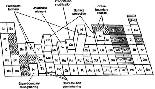
31 The main difference between the two protection systems is the adhesion of the coating; this aspect is fundamental: in a rotating turbine running at thousands of revolutions per minute, a leak of the coating will cause a damage to the system. In power generation applications, this results in an implant stop, and restoration of the naked component exposed to surface degradation phenomena. As far as aeronautical applications are concerned, having high-speed projected elements inside the engine can cause the engine to lock itself. Figure 2.6 describes properties and compositions of the typically used antioxidant coatings. It is to be noted that Al and / or Cr coatings have excellent oxidation behavior as they rapidly form a slow-growth protective oxide (Al2O3 and Cr2O3) scale; when Cr content
increases, an improvement in corrosion resistance is observed;
Figure 2.6:Compositions and properties, in terms of oxidation and corrosion resistance, for several coatings [2]
2.3 Diffusion aluminide coatings
In this type of protective coating, the surface is enriched with aluminum which, as said, is able to form a slow-growth protective oxide scale. Depending on the surface, Al reacts chemically with the substrate in Ni, forming a new phase called b-NiAl; it will be the aluminum present in this intermetallic to undergo oxidation by protecting the underlying substrate. Figure 2.7 shows the result of 2500 hours flight at low altitudes at sea level on a turbine blade. The macroscopic difference between a non-coated blade and a protected b-NiAl layer is evident.
32
Figure 2.7: Aluminized and not coated turbine blades
In general, diffusive coatings can easily cover complex shapes and inner surfaces, which are generally complicated to coat; there is no substrate-coating interface, so there are no adhesion problems since the coating is contained in the component, there are no elements that can be detached. The process is very reproducible, as it is driven by thermodynamics, and finally the apparatus is economical. Conversely, the diffusing coating that is formed cannot be different from the substrate composition, since from a chemical point of view the reaction takes place between the substrate and the gas containing the element that will diffuse inside. Another negative aspect is that the substrate to be coated should be exposed to high temperatures: superalloys undergo very complicated high temperature thermal treatments, and the risk is that by enriching the surface at temperatures comparable to those with which these treatments are performed, the resulting hardening may be lost and the substrate properties may be compromised.
Stages of equilibrium of Ni-Al alloy
Ni crystallizes in a cubic face centered structure (CFC). If Ni is allied with Al, there are many changes. Up to an approximately 4 wt% Al, there is no change in the Ni atomic structure, except for occasional random replacement of Al atoms against Ni; This phase is called g phase and is characterized by CFC structure (Figure 2.8a).
By increasing the content of Al, it selectively begins to replace Ni atoms at the angles of the cell, while the atoms on the cube faces remain of Ni (Figure 2.8b). The ratio of the atoms to each cell is 1 every 3 Ni, giving the Ni3Al composition, known as g' phase.
33 If the alloying is increased up to 25 wt% Al, the crystalline structure changes, giving rise to an ordered biatomic cubic structure. The ratio between Al and Ni atoms is 1: 1, providing the NiAl composition, known as phase b, (Figure 2.8c).
Figure 2.8:Allotropic phases of NiAl
The Ni-Al binary phase diagram, shown in Figure 2.9, may provide useful information on the phase that is characterized aluminide coating obtained by diffusion over Ni-based superalloys.
Figure 2.9: Ni-Al diagram phase
The field of the b phase is very wide, indicating that at this stage the concentration of Al can be very far from the stoichiometric NiAl composition. In addition, the melting point of the b phase is much higher than the pure Ni. These characteristics make the b phase very favorable for use in high temperature coatings.
34
2.4 Platinum modified aluminide coatings
The deposition of an electrolytic platinum layer before the aluminization, followed by a diffusion thermal treatment (at 1000 ÷ 1100 ° C, up to 5 hours at 10-7 torr) was initially designated to create a barrier against the diffusion of aluminum towards the substrate, delaying the decomposition of NiAl to Ni2Al3.Subsequent analyzes have shown that Pt does not act as a diffusion barrier, and a number
of other mechanisms have been proposed to explain the effective role of Pt in increasing the oxidation and corrosion resistance of aluminide, because this element does not participate directly to the formation of the protective oxide scale. Figure 2.10 shows how the presence of Pt increase the performance of an aluminide in terms of hot corrosion resistance:
Figure 2.10: Comparison of hot corrosion resistance for a simple aluminide coating, a platinum modified aluminide
coating and a CoNiCrAlY overlay coating
As mentioned, the mechanisms through which platinum acts on the bond coat properties are not clear. For example, it has been shown that the formation of the phase PtAl2 increase the quantity of
the aluminum inside the bond coat, with the consequent increasing of the selective oxidation of the Al [4]. This is essentially due to two factors:
1. No platinum oxide is formed at operating temperatures; 2. Al is very mobile in rich platinum phases.
35 This results in an alumina scale with increased purity and reduced growth rate. The efficacy with which platinum performs this action is related to an optimum concentration of Pt, which in excessive amounts would brittle the superalloy, and greatly increase the process costs.
In addition, it suppresses the precipitation of Cr rich phases inside the outer layer of the coating. In fact, Cr in solid solution increases the activity of the Al near the surface; this benefit is less in the presence of precipitates, which therefore results in a reduction in the oxidation resistance of the coating. Pt also suppresses the diffusion of refractory elements such as Mo, V and W from the alloy to the outer layer and improves the stability of the coatings against the inter-diffusion between the substrate and coating itself, preventing the phase transformation from b to Ni-richer phases [5]. Finally, it suppresses the formation of voids at the interface, thus increasing the adhesion of the scale to the coating [6].
2.5 Modified diffusion aluminide coating with reactive elements
It has been known for more than 70 years that the addition of small quantities of reactive elements (RE), generally transition elements such as Hf, Zr, Y, Si, La or Ce, has beneficial effects on the oxidation behavior of aluminide. They take the name of reactive elements because they themselves react in the coating during oxidation.
Pfeil in 1937 [7] was the first to report the beneficial effects of the RE; Since then, the scientific literature agrees on the best adhesion of the oxide and the reduction of the rate of growth of the scale in Ni-based superalloys [8].
Figure 2.11 clearly shows the benefits introduced by RE on oxidation rate. The kP of a b-NiAl
36
Figure 2.11: RE effects on weight gain of b-NiAl doped
The actual mechanisms that take place for the RE are a very controversial topic from a scientific point of view. In general, the mechanisms proposed were:
• REs segregate as ions along the polycrystalline oxide scale grain boundaries, significantly limiting the transport to the outside of aluminum and thus reducing the rate of growth of the oxide. From a combined contribution of both aluminum and oxygen in the absence of reactive elements, oxidation is mainly governed by oxygen transport. It has been experimentally observed that the rate of growth of the oxide scale is influenced differently depending on the element forming it: in Al2O3 there is a
reduction in the speed of about 2-4 × while in Cr2O3 of a factor 10-100 ×.
• REs segregate as ions, but are not static, but spread outward during oxidation, driven by the Dyanamic Segregation Theory [10].
• REs occupy reticular vacations, causing decreasing of Kirkendall voids formation at bond coat / oxide scale interface: Al and Ni interdiffuse with different speeds, causing the formation and coalescence of voids, which reduces adhesion of the scale of oxide to the substrate [10],[11].
• REs cause the formation of oxide pegs in the substrate, which improve adhesion to the interface by means of a real mechanical anchorage: the reactive element oxides grow by internal oxidation below the scale. The distribution of these pegs is a function of solubility: reactive elements with higher solubility result in the formation of more thin oxide pegs than those with limited solubility [12].
37 • The REs bind to S, inhibiting its segregation to the oxide-substrate scale interface: in fact, the presence of S at the interface lowers the cavity formation energy, which would affect the adhesion of the oxide scale [13].
• The REs determine strong interactions with the oxide interface: Density Functional Theory (DFT) principles based on theoretical calculations indicate that the first transition elements, characterized by open electronic shells, are able to determine, added to bond coat, bond-to-bond interactions to the strongest interface.
In practice, it is believed that co-sharing of these mechanisms causes a beneficial effect on oxidation and hot corrosion resistance [14].
2.5.1 State of the art
It is preferred to use reactive elements with a high atomic radius such as Zr and Hf, because they can react more easily thanks to their atomic dimensions.
Guo et al [15] compared the behavior of some coatings after 100h of cyclic oxidation at 1200 ° C, showing that among all the compositions studied, indeed, doped aluminide with Hf, Zr and an Hf-Zr blend are those which presented a greater oxidation resistance (Figure 2.12) with a lower kP.
38
Figure 2.12: Square weight gain (sample + spalling) for NiAl with different amount of RE during 100h cycles at 1200°C
in air: (a) NiAl–0.05%Dy–0.05%Hf, NiAl–0.05% Dy e NiAl–0.05 %Hf ; (b) NiAl–0.05%Hf–0.05% Zr, NiAl–0.05% Hf e NiAl–0.09% Zr ; (c) NiAl–0.05% Hf–0.05%La, NiAl–0.05% Hf e NiAl–0.09% La ; (d) NiAl–0.05% Y–0.05%La, NiAl– 0.06% Y e NiAl–0.09% La
Guo suggested that Hf and Zr cations segregate to the oxide grain boundaries by interacting with oxygen (Figure 2.13); Moreover, if deposited together, they form an ionic group that synergistically produces stronger interactions than the two individual ions.
39 Hamadi et al. [17] characterized a doped NiAl coating with Zr; Figure 2.14 shows the concentration profile of the Zr obtained by GDMS, in which it is noted that the RE moves to the interface between the interdiffusion zone and b-NiAl.
Figure 2.14: Cross-section of the coating with the Zr profile
The cyclic oxidation resistance of the AM1 / NiAl (Zr) system was compared to that of the AM1 / NiAl system to obtain the effect of Zr; In addition, the AM1 / (Ni, Pt) Al system has also been taken as an industrial reference. From the curves shown in Figure 2.15 it is shown that the behavior of the doped lining with Zr is absolutely comparable to Pt aluminum.
Figure 2.15: Mass variation vs time for cyclic oxidation tests at 1100°C
SEM (Figure 2.16) analysis also showed that after 250 cycles, spallation and oxidation phenomena are present on the coating surface of NiAl, while appearing on the surface of the modified coating only after 500 cycles. Moreover, in the case of NiAl, the spallation zones reveal the presence of
40 numerous cavities at the intermetallic-oxide interface; these cavities have not been observed in the doped coating
Figure 2.16: Cross-section SEM micrographs of oxidized sample AM1/NiAl (on the left) and AM1/NiAl (Zr – on the
right) after: a) 50 cycles; b) 250 cycles; c) 500 cycles of oxidation tests at 1100°C. In the figure b, the arrows indicate the cavities[18].
41 Figure 2.17 compares the isothermal oxidation behavior of modified aluminide and simple aluminide coatings.
Figure 2.17: Change in weight after 100h of isothermal oxidation at 1100 ° C of doped and standard NiAl coating.
In the first 3h the gain by weight is significant, and corresponds to the transient oxidation regime; at this stage, oxides of all the constituents of the alloy are formed, provided that under such conditions the relative free energy variation is negative. By the progress of the oxidative process, it is expected that the thermodynamically stable oxide predominates with respect to the others. The metastable phases of the alumina (g, d, q), do not have the same protective action as it guarantees the a-Al2O3.
Therefore, avoiding or minimizing transient oxidation processes improves the protective action of the oxide scale.
Subsequently, oxide growth reaches a steady state. Between 20 and 100h the curves for both coatings have the same pattern and thus the same steady oxidation regime.
The data show that with Zr the transient oxidation phase is reduced by a factor of 2. This may be due to or to inhibition of the transport to the outside of the Al, which thus promotes anionic oxidation and the growth of a-Al2O3, or to the growth of q-Al2O3 nucleation.
References
[1] Y. Tamarin, ASM International, Ohio, 2002.
[2] J.R. Nicholls, Journal of metals, 52 (1), pp. 28-35, 2000.
[3] N.P. Padture, M. Gell, and E.H. Jordan, Science, 296 pp. 280-284, 2002. [4] J. R. Nicholls, “Designing Oxidation-Resistant Coatings,” no. January, 2000.
[5] A. G. Evans, D. R. Mumm, J. W. Hutchinson, G. H. Meier, and F. S. Pettit, ,” Prog. Mater.
Sci., vol. 46, no. 5, pp. 505–553, 2001.
42 [7] Tawancy H. M.; Sridhar N.; Abbas N. M., “Journal of Materials Science, 35 (2000), p.
3615-3629.
[8] G.W. Meetham, Mater. Sci. Eng. 2 (1986) 290.
[9] G.W. Goward, Surf. Coat. Technol. 108-109 (1998) 73-79.
[10] D. P. Whittle, J. Stringer, Phil. Trans. R. Soc. Lond. A, (1980) 295 [11] J.D. Kuenzly and D.L. Douglass: Oxid. Met. Vol. 8 (1974), p. 139
[12] R. Bianco and R. A. Rapp, J. Electrochem. Soc. (1993) vol. 140, issue 4, 1181-1190 [13] ee, W.Y., Wright, I.G., Pint, B.A. et al. Metall and Mat Trans A (1998) 29: 833 [14] B. A. Pint, Oxid. Met. 45 (1996) 1-37.
[15] B.A. Pint, Proc. of the J. Stringer Symposium, November 2001. [16] M.W. Brumm, H.J. Grabke, Corros. Sci. 34, 547, 1993.
[17] H. Guo et al., Corrosion Science 88 (2014) 197–208.
43
CHAPTER 3
Processes for production of diffusion aluminide coatings
3.1 Coating technique
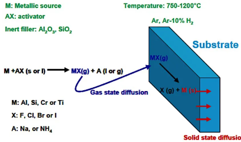
Diffusion coatings are obtained from an alloy that is superficially enriched with elements capable of forming oxide scale such as Al, Cr, Si, or combinations [1], up to a depth of 10 ÷ 100 µm. These elements bind to the primary elements of the alloy, resulting in intermetallics. This type of coating can be obtained by various techniques, as shown in Figure 3.1:
Figure 3.1: Diffusion coating technique
Figure 3.2 describes the process steps generally common to all techniques, which are:
• Generation of vapors, generally halide, containing the element that will form the protective oxide scale (Al, Cr or Si);
• Gas transport to the surface of the component, by a partial pressure gradient;
• Gas reaction with substrate followed by solid state diffusion processes within the alloy;
• Additional thermal treatments, if needed, to obtain the desired composition and coating properties.
44 From a thermodynamic point of view, the most important chemical reactions are those related to the formation of volatile halide and its decomposition, and those related to solid state diffusion. There are therefore two crucial temperatures for the correct deposition of an element: the temperature that allows the formation of the gaseous halide and the one that activates the diffusion.
The microstructure, the activity of the Al (or Cr, Si) within the coating and the thickness of the coating depend on the alloy used as substrate, on the process parameters and on the following heat treatment selected.
3.2 Growing mechanism of diffusion coatings
There are two mechanisms for a diffusive coating formation, depending if the main diffusing species is aluminum inside the substrate or is the Ni diffusing outwardly. The two mechanisms lead to the achievement of different types of coatings, known as inward and outward coatings.
There are, therefore, two distinct process, which differ in the term of the Al activity in the gaseous phase and process temperatures:
• High Temperature, Low Activity HTLA • Low Temperature, High Activity LHTA
The activity of a gaseous phase can be approximated, at low pressures, with the ratio between the partial pressure of the gas and the atmospheric pressure. High activity involves high partial pressure, which in the specific case indicates the availability of Al-gaseous halide.
3.2.1 High Temperature Low Activity Process
This method applies a high temperature (> 1000 ° C), for a time ranging from 3 to 4 hours, in the presence of a low activity of the Al (HTLA).
It is a "single-stage" method with the outward diffusion of the Ni and the subsequent reaction with Al to form the b-NiAl coating: the growth of this phase is therefore going outward. In practice, Al also diffuses into the substrate, resulting in coating growth in that direction, but this contribution is significantly lower than that due to the transport of the Ni (DNi> DAl). Conversely, the diffusion of Ni
to the outside causes the formation of a poor Ni area just below the original surface of the substrate; such a zone can be a phase precipitate rich in metal elements and is commonly referred to as interdiffusion zone (IDZ).
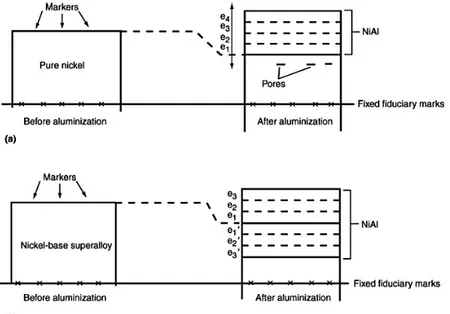
45 Figure 3.3 shows schematically the progressive stages that characterize the deposition. It is noted that, as compared to the surface of the substrate, the coating has grown outwardly.
Figure 3.3: Schema for the progressive stages of aluminization by HTLA pack cementation – a) Pure Ni (e1 is formed
firstly, then e2,e3 and so on); b) Ni-based super alloy (e1 and e1’ are formed firstly, then the others) [2]
As mentioned, the outside diffusion of the Ni is much faster than the diffusion of aluminum. This difference between the two speeds involves the voids, known as Kirkendall voids near the original interface (Figure 3.3a). The advancement of the process causes, in a Ni-based superalloy, a depletion of Ni in its respective areas within the alloy (Figure 3.3b). Thus, when a layer e1 is formed externally, a corresponding layer, depleted in Ni, forms inside the alloy, and so on. This technique therefore allows to obtain a b-NiAl coating, which is however accompanied by the presence of precipitates (such as TiCs) that are not soluble in the intermetallic matrix (Figure 3.4).
46 Figure 3.5 shows in section a sample aluminized by HTLA pack cemetation. It is noted that this coating is characterized by two areas, which are roughly the same thickness:
• External β-NiAl layer
• Intermediate area, poor in Ni with heavier element precipitates
Figure 3.5: Ni-based superalloy aluminized by HTLA pack cementation [3]
3.2.2 Low Temperature High Activity Process
In this method the deposition takes place at low temperature (LTHA) and involves the execution of two steps: a low temperature deposition (700 - 850 ° C) followed by diffusion annealing at temperatures above 1000 ° C . Downstream of the first step, the coating is made up of an excessively rich phase in aluminum (d-Ni2Al3 or d-Ni2Al3 + b-NiAl rich in aluminum), carbides and precipitates
of the various constituent elements. This microstructure is due to the diffusion into the interior of the inward diffusion, which causes an increase in the interior of the coating (DAl> DNi). During the second
stage (diffusion treatment), the Ni moves outwards leading to b-NiAl formation, quite similar to HTLA mode. This step is crucial, as the d-Ni2Al3 phase is a fragile phase with mechanical properties
much lower than b-NiAl. Again, in this case, the formation of an interdiffusion zone is provided at the interface between the coating and the substrate.
Figure 3.6 shows the first stage of deposition, the aluminization. It is noted that, as compared to the surface of the substrate, the coating is increased inward.
47
Figure 3.6: Schema for the progressive stages of aluminization by LTHA pack cementation – a) Pure Ni (e1 is formed
firstly, then e2,e3 and so on); b) Ni-based super alloy (e1 is formed firstly, then the others) Figure 3.7 shows the final microstructure; this consists of:
an outer layer of b-NiAl with carbides and precipitates of substrate elements that were formerly bonded to Ni, an intermediate layer of b-NiAl free of carbides and precipitates, and finally an interdiffusion area. In addition, it is noted that during the thermal treatment, following the aluminization, the coating is characterized by a portion of growth towards the outside, due to the activation of the Ni diffusion outwardly.
48
Figure 3.7: Final structure of a Ni-based super alloy coated by LTHA pack cementation
Figure 3.8 shows a section of an aluminized sample by pack cemetation LTHA. It is noted that the b-NiAl thickness is substantially larger than that of the interdiffusion zone.
Figure 3.8: Ni-based superalloy aluminized by LTHA pack cementation
3.3 Pack Cementation
In this process, the components to be coated are first cleaned, generally by means of alumina blasting to remove oxides and contaminants from the surface. If necessary, the area of the component to be protected from deposition of the coating is masked with a material that can withstand the process temperatures without going against degradation. At this point, as shown in Figure 3.9, the components are buried in a mixture of powders (packs) inside a sealed (or semisealed) reactor. The reactor is then
49 inserted into a furnace and heated in an inert atmosphere (Ar or H2), in order to avoid the oxidation of the elements that will produce the coating in the pack.
Figure 3.9: Pack cementation process
The reactor is composed of materials that do not degrade at process temperatures such as Inconel alloys and stainless steels 310, 321 and 347.
Powders contain:
• The aluminum source (or Cr, Si), generally called master alloy.
• An "activator" salt, usually an ammonium or sodium halide, which, by reaction with the source, will form the gaseous species containing aluminum and transport it to the surface to be coated.
• An inert filler, such as powdered alumina, designed to create interconnected porosity for gas transport and prevent sintering, which would occur at process temperatures.
The inert filler is not always indispensable; the choice depends on what type of Al source is used. Generally, in LTHA processes, it is preferred to use Al pure as a master alloy, which allows to cast more gas in the gas phase, resulting in a greater availability of the deposition elements. However, choosing a low-core element involves the need to adopt an inert filler that prevents the sintering of the pack. If this is not used, there will be difficulties in recovering the components.
In HTLA processes Al (Al-Cr, Al-Co) alloys are generally used as the source; The filler is not necessary, in this case, because of high melting point of the master alloy
A salt, to be suitable for activating a pack cementation, must be necessarily unstable, to react at the process temperatures. Salt selection guidelines are the following:
50 The anion is generally a halide. Concernign the cation, ammonium salts are preferred because they decompose to high T, producing H2 that increase the reducting atmosphere.
The reaction that the activating salt has with the component depends on the type of salt used. In the case of NH4Cl, NH4Br and NH4I (Figure 3.10a), the halide stays in the gas phase even after reaction with the substrate and deposits only solid Al: there are no co-products that can be deposited on the surface of the component. The F is still used, despite the disadvantage of ist utilization, since it is characterized by high partial pressure, therefore forms AlF very easily. Finally, using Na-halides (Figure 3.10c), instead of solid precipitates, there are liquids on the surface.
Figure 3.10: Mechanism of reaction and diffusion for different activator salts
The reactions between NH4X ammonium halide and a substrate in Ni-base super alloy are as follows: • Decomposition of NH4X
NH4X(s)=NH3 g +HX(g) (3.1)
• Volatile Al halide formation
6HX(g)+2Alpack=2AlX3 g +3H2(g) (3.2)
2AlX3 g+2Alpack=3AlX(g) (3.3)
• Al deposition on top of the substrate
2AlX g+3Nisub=2NiAlalloy+NiX2(g) (3.4)
51
3AlX g+2Nisub=2NiAlalloy+AlX3(g) (3.6)
2AlX g+2Nisub=2NiAlalloy+X2(g) (3.7)
2AlX g+H2(g)+2Nisub=2NiAlalloy+2HX(g) (3.8)
where reactions (3.4) and (3.5) are displacement reactions, disproportionation (3.6), decomposition (3.7), and finally reduction reaction (3.8).
The advantages of this technology are: 1. the exercise at atmospheric pressure; 2. the good reproducibility of the coating and
3. low plant costs, since the latter is essentially a furnace.
The main disadvantages concern the limited flexibility of the process in terms of coating composition and the length of the process for high thicknesses. In addition, pack particles may be trapped in the outer layer of the coating: this phenomenon is generally negative since such inclusions will prevent the formation of a continuous oxide scale.
3.1.1 Process above the pack
This process works very similar to that discussed in Section 3.3, with the exception that the components to be coated are placed above the powders containing Al.
Al transport from the pack to the substrate occurs by gas phase diffusion while the substrate surface inside for solid phase diffusion. The first type of diffusion increases the surface concentration of Al in the coating while the second decreases it to a steady state. In the vapor phase, the Al transport rate is much faster than solid phase diffusion within the substrate, which is therefore the deciding step for the deposition rate. Finally, there is the diffusion of reaction products from the substrate to the outside of the reactor, which controls the purity of the coating.
52
Figure 3.11: Above the pack process
A typical temperature profile of the above the pack aluminization process is shown in Figure 3.12:
Figure 3.12: Profile temperature in a out-of-pack process
This method, as compared to standard pack cementation, simplifies the process of unpacking components from dust; Moreover, it allows for a much cleaner and homogenous coating, even for complex geometry components, without embedding of particles during the process.
Another variant, more technological than concept, is VPA (Vapour Phase Aluminizing); the only difference lies in the fact that no more dusts but pellets are used. The advantage is the simplification of the charge and discharge processes of Al source, since no volatile metallic dust is formed: this in fact provides for the most in-worker protection systems and under a certain dimension can become dangerous (pyrophoric phenomenon). Finally, it is easier to ignore the waste of the process: once depletion of Al under some concentration occurs, the source is exhausted and can be replaced and reloaded more easily.
53
3.4 Slurry aluminization
The coatings obtained by this technique offer a very similar chemical composition to that found in alluminide products by pack cementation. In this process, powders and activators are mixed with an organic binder (or an aqueous emulsion) to obtain a slurry. The coating is applied to the substrate by immersion or spraying at room temperature; then undergoes a low temperature treatment treatment, typically around 200 ° C. After this, the diffusion process of the Al is activated: the components are brought to temperature (650 ÷ 1100 ° C), which varies depending on the substrate to be coated and its final use.
With this technique, it is easy to restore if necessary parts of the coating, since it is possible to apply the slurry locally. However, it is less clean than above the pack as it introduces an interface between a solid precursor and the component; all those reactions between the gas and the surface become reactions between a solution and the component, which will then be covered with that part of the slurry that has not reacted. At the end of the treatment, you will need to clean up the residues present, which is not trivial when you want to cover the cavities.
References
[1] Z.D. Xiang, P.K. Datta, Mat. Sc. and Eng. A356 (2003) 136/144
[2] R. Pichoir, Corrosion, D.R. Holmes and A. Rahmel, Ed.,(1978) Applied Science Publishers Ltd., London p 271.
![Figure 2.6:Compositions and properties, in terms of oxidation and corrosion resistance, for several coatings [2]](https://thumb-eu.123doks.com/thumbv2/123dokorg/2896145.11682/31.892.258.630.420.770/figure-compositions-properties-terms-oxidation-corrosion-resistance-coatings.webp)