T
his article introduces and de-scribes an electrically powered full-body (FB) exoskeleton, called the body extender (BE), intended as a research platform for the study of the transport and handling of heavy loads up to 50 kg, with one hand at worst-load conditions (WLCs). The machine features a 22-degrees-of-freedom (DoF) quasi-anthropomorphic kinemat-ic scheme and a modular hardware/software architecture that made it possible to manage the complexity of the system design. Besides providing a context and some general guidelines, which have driven the design of the BE, this article presents the hardware and software devel-opments that have been achieved and imple-mented in the machine. The experimental results are shown that prove the functionalities of the BE in common operating conditions such as walking, squatting, and handling loads. The one-of-a-kind system demonstrates, in relevant laboratory settings, the feasi-bility of a complex, electrically powered full-body exoskeleton with such a target payload.Human Performance Augmentation
Exoskeletons for human performance augmentation (EHPAs) belong to a special class of wearable mechatronic/ robotic systems that are placed in parallel to the operator’s body with the aim of increasing its strength and/or endurance [1]. Unlike other kinds of robotic assistants, EHPAs are fully
controlled by the wearer and move in synchronism with her/ his limbs. Practical applications of EHPAs include physical assistance of the elderly and disabled, functional rehabilita-tion of injured persons, and fatigue relief and protecrehabilita-tion of heavy-duty workers.
Because of the dramatic progress in disciplines such as computing, sensing, and control, in recent decades, a signifi-cant number of EHPA prototypes for the upper or lower ex-tremities have been conceived and developed in research laboratories, with some of these systems currently being tested for medical approval or released for commercialization.
Digital Object Identifier 10.1109/MRA.2014.2360287 Date of publication: 19 December 2014
The Body Extender
The Body Extender
By Marco Fontana, Rocco Vertechy, Simone Marcheschi, Fabio Salsedo, and Massimo Bergamasco
A Full-Body Exoskeleton for the Transport
and Handling of Heavy Loads
Despite the considerable interest and impressive advance-ments in the field, so far only a few researchers have attempted the development of FB-EHPAs, in particular, fully actuated systems for heavy-duty applications, and the available scientif-ic literature is quite limited [1]–[14].
The first technical concepts of FB-EHPAs were proposed in 1956 by Lent, who proposed an inflatable space suit with pow-ered joints to assist the wearer during the flexion of suit ex-tremities [5], and in 1966 by Mizen, who proposed the first man amplifier for civilian and military applications [6]. The first practical investigation was instead attempted by General Electric between 1965 and 1971, which developed the Hardiman [7], a hydraulically powered FB-EHPA featuring: 1) 30 active joints under force-feedback control, 2) the ability to manipulate a 340-kg payload in the WLC, i.e., with one arm at full horizontal extension, 3) a self-weight of 680 kg, and 4) a power consumption of about 45 kW.
In 1996, Kazerooni proposed a novel underactuated mate-rial handling system with eight passive joints (three for each leg and one for each arm) and 18 electrically actuated joints (four for each leg and five for each arm) under force-feedback control [8]. However, no information is available on the over-all system performances and specifications, or on the testing of the entire system (the arms and legs appear to have only been implemented and tested separately).
From 2002 to 2009, three different underactuated FB-EHPAs were developed in Japan for medium-duty applications, such as nursing care [9], disabled or elderly assistance [10], and agriculture [11]. Among these three exoskeletons, the most re-nowned system is the hybrid assistive limb (HAL) [10], which features: 1) eight electrically actuated joints (two for each leg and two for each arm), 2) a controller involving bioelectrical signals from the wearer’s muscles, 3) the ability to manipulate a 15-kg payload WLC, and 4) a system mass of 23 kg.
In 2009, Panasonic Activelink presented the power loader, a heavy-duty FB-EHPA featuring 18 electrically actuated joints (three for the each leg and six for each arm). Although limited information is disclosed [12], the power loader weighs 230 kg and is capable of manipulating a 50-kg payload WLC.
In 2010, Raytheon-Sarcos unveiled the XOS2 [13], which is one of the most advanced medium-duty FB-EHPAs available to date in terms of completeness (i.e., includes arms and legs) and complexity. Although explicit specifications are not avail-able, XOS2 should comprise 23 hydraulically actuated joints (six for each leg, one for the torso, and five for each arm), weigh 95 kg, and be capable of manipulating a 23-kg payload WLC and walking at velocities higher than 1.5 m/s.
In 2012, the French company RB3D presented the Hercule, an electrically actuated FB-EHPA with legs similar to HAL but with different arm kinematics, designed for lifting 20 kg WLC. Hercule was developed for the French Ministry of Defense; the detailed system specifications are not available at present.
In this context, this article describes a novel electrically ac-tuated FB-EHPA, hereafter called BE, which has been de-signed for heavy-duty low-speed material handling activities in unstructured environments. The final envisaged application
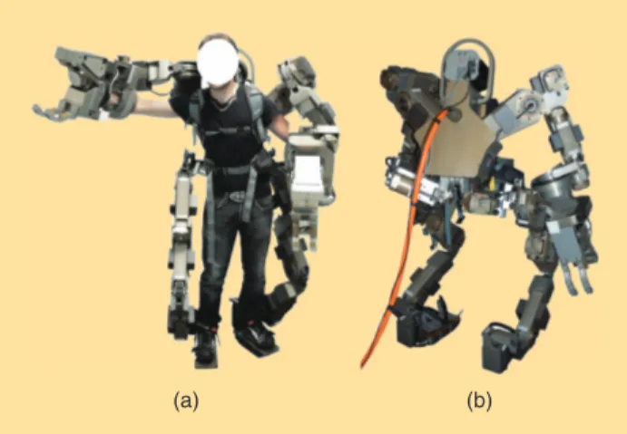
is in the fields of logistics and disaster intervention. Photos of the BE prototype are provided in Figure 1 [14]. The machine is the first prototype intended as a research platform for studying human-exoskeleton interaction and developing novel control strategies. The system comprises two identical legs with 6 DoF each and two identical arms with 5 DoF each. All 22 DoF are powered by modular highly efficient actuation units, which make it possible to limit the power consumption as well as minimize the costs and efforts associated with its manufactur-ing and maintenance. The BE weighs approximately 160 kg (power supply excluded), is capable of lifting 50 kg with one arm at WLC, and can potentially transport loads up to 100 kg at a walking speed of 0.5 m/s.
Motivation and Architectural Choices
Machinery and automation have significantly reduced the demand for hard hand labor in industrial and service appli-cations. However, there are several settings in which heavy work by humans is still compulsory. Examples are: 1) small-batch manufacturing and assembling of large parts such as airplane and ship components, 2) construction and demoli-tion of buildings, roads, and railways, 3) underground min-ing, and 4) emergency and postdisaster services that include the search and rescue of victims as well as the restoration and decommissioning of damaged civil infrastructures. These ap-plications typically involve lifting and carrying heavy objects (even exceeding 20 or 40 kg for frequent or sporadic events, respectively) in unstructured/unknown environments and difficult terrains. Ideally, machines providing support to hu-mans in these situations should be intelligent, flexible, agile, and dexterous with cognitive, locomotion, and manipulation capabilities that are similar to those of humans but with the strength, power, endurance, and precision of a machine.
In these scenarios, while humanoid and animaloid robots could be an option in the future, active exoskeletons can defi-nitely be a solution in the shorter term, at least for all those ac-tivities that do not pose significant threats to operator health
Figure 1. The (a) front and (b) back view of the BE, a prototype of a whole body exoskeleton developed by the PERCRO Laboratory of the Scuola Superiore Sant’ Anna (photos courtesy of the PERCRO Laboratory, TeCIP Institute, Scuola Superiore Sant’Anna).
and safety. Active exoskeletons, in fact, share the same work space of the operator and are directly commanded by her/his intention, without necessitating significant usage and/or specif-ic advancements in telepresence and/or artifspecif-icial intelligence.
In this context, the Perceptual Robotics (PERCRO) labora-tory of the Scuola Superiore Sant’Anna recently completed the development of the first prototype of the BE, an FB-EHPA de-signed as a research platform to investigate the potentials and limitations of active exoskeletons in the assistance of human operators executing from medium- to very-heavy-duty works (specifically including the frequent lifting and carrying of ob-jects that are too heavy to be managed by one or a few individuals).
The development of the BE has been conducted consider-ing the followconsider-ing set of guidelines:
1) compliance to basic tasks such as object lifting, handling, and transportation
2) natural/intuitive guidance 3) stability for normal static walking
4) high power-to-weight density and reduced energy consumption
5) an onboard controller with a fast sampling rate and easy programmability
6) reduced system costs and simplified maintenance 7) reduced encumbrance with close adherence to the
wear-er’s body
8) a work space matched to the operator’s range of motion 9) sufficient adaptability to individual differences in wearers’
anthropometric dimensions and locomotor functions without the use of mechanical regulation or tunings 10) easy wearability.
Since the concurrent and flawless compliance with all such requirements is highly desirable but extremely hard to achieve in practice, the final design of the BE has gone through a number of tradeoffs. In particular, to best comply with these guidelines, the following architectural choices have been made:
●
● The kinematics chains of the robot are attached to the us-er’s body only at the end-effector points (hands and feet) and the torso (this makes the BE sufficiently compliant with guidelines 1, 2, and 7–10).
●
● The lightweight structural components are made of high-performance materials and with thin-wall structural ele-ments to comply with guideline 4.
●
● The mass is distributed so as to make the BE statically bal-anced as it follows the natural movements of the user dur-ing walkdur-ing [20] (this makes the BE sufficiently compliant with guideline 3).
●
● Electrical actuation has been preferred over hydraulic, which is usually employed in this power-force range so as to obtain a more efficient use of energy and to simplify sys-tem maintenance (this makes the BE sufficiently compliant with guidelines 4 and 6).
●
● A modular architecture that employs a single kind of elec-tric motor and electronics for most of the joints of the robot to be sufficiently compliant with guidelines 5 and 6.
The overall performances of the BE are shown in Table 1. In the following sections, several details of the mechanical, electronic, and control development of the whole system are provided along with experimental test and validation results.
Kinematics
The proper choice and design of the kinematic architecture of an FB-EHPA is a fundamental step in the development pro-cess since it strongly affects the basic functionalities and capa-bilities of the resulting machine. Anthropomorphic solutions, i.e., replicating the kinematics of human limbs, are commonly adopted for robotic exoskeletons as they make it possible to 1) achieve optimal work space matching with reduced en-cumbrances, 2) obtain a simple strategy to avoid self/body collisions, 3) guarantee the execution of natural movements, and 4) maximize adherence to the operator’s body. While a fully anthropomorphic design is very desirable, some devia-tions may be introduced to provide other features in addition to those mentioned earlier.
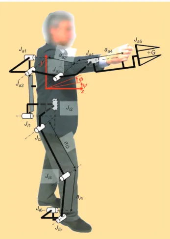
In this perspective, the kinematic architecture of the BE has been conceived according to a quasi-anthropomorphic scheme, i.e., a kinematics that is very close to that of the wearer if not for slight differences that have been introduced with the aim of simplifying the implementation, avoiding singular configurations, and guaranteeing immediate adapt-ability to different users. In particular, the BE has been de-signed to be worn by operators whose anthropometric dimensional data are within the third and 97th percentile of western males [15] (i.e., with stature ranging from 1.65 and 1.90 m). The machine features 6 DoF at each leg, which pro-vides maximal locomotion flexibility, and 4 DoF at each arm (plus one grasping DoF at each hand), which reduces the sys-tem complexity while preserving essential object handling functionalities. Given the required payload capabilities, all of the considered 22 DoF are actuated. A schematic of the de-tailed kinematic architecture of the BE is shown in Figure 2 (owing to bilateral symmetry, only the right half of the
Table 1. The main features of the prototype of the BE.
Features Values/Description Units
Exoskeleton type Full body NA
Kinematics type Quasi-anthropomorphic NA
DoF 22 (all actuated) NA
Total mass 160 kg
Maximum force WLC 500 N
Actuation Electric (modular) NA
Maximum continuous
torque (at motor axis) 5 Nm
Maximum speed
(at motor axis) 1,300 r/min
Motor power 680 W
Gripper type Parallel NA
Power supply Grounded battery pack 17.5 kWh
system is depicted). In the figure, the coordinate system x y z- - indicates a Cartesian reference frame fixed to the BE torso, with the z and y axis corresponding, respectively, to the sagittal and longitudinal axis.
An interaction between the BE and the wearer occurs at the level of the hands by means of handles, the torso by means of shoulder straps and a belt, and the feet by means of boot bindings.
Legs
Regarding the lower extremity, the BE comprises two sym-metrically identical legs, each featuring two limbs (the upper and lower leg) and one foot. Referring to Figure 2, the upper leg is connected to the BE torso via a spherical joint formed by three consecutive revolute joints ,^J Jl1 l2 and )Jl3 with
orthogo-nal and intersecting axes. The upper leg is connected to the lower leg via a single revolute joint .Jl4 The lower leg is
con-nected to the foot via a universal joint formed by two consecu-tive revolute joints ( Jl5 and Jl6) with orthogonal and
intersecting axes.
As depicted in Figure 2, the centers of the spherical and universal joints of the BE leg are approximately collocated with those of the wearer’s hip and ankle. The revolute axis of Jl1 is inclined by an azimuth angle }l=-0 152. rad (Figure 2). To remove the mechanical interference at hip level, the internal/external rotation of the BE hip (namely, the rotation provided by Jl2) is implemented through a
par-allelogram-based remote-center-of-rotation mechanism [16] (Figure 3). Joints , ,J Jl3 l5 and Jl4 have parallel axes, the
for-mer two approximately coinciding with the wearer’s hip flex-ion/extension and ankle dorsiflexion/plantarflexion axes, whereas the latter are parallel to the wearer’s knee flexion/ex-tension axis; the distances of the axes Jl3 and Jl5 from that of
Jl4 are al3= 0.540 m and al4= 0.445 m, respectively. Within
the limits of physical realizability and system compactness, the lengths al3 and al4 (and the related noncoaxiality of Jl4
with respect to the wearer’s knee joint axis) have been cho-sen to bring the knee singularity of the BE outside the reach-able work space of the user’s leg and to reduce the highest rotating speed among those provided by joints , ,J Jl3 l4 and
Jl5 during walking (for the entire population of the
consid-ered human users). Depending on the wearer’s size, the ob-tained reduction in the highest joint speed is in the range of 8–15% with respect to that of a similar FB-EHPA with Jl4
coaxial to the wearer’s knee joint. The revolute axis of Jl6 is
approximately coincident to the ankle abduction/adduction axis of the wearer. Unlike the human lower limb, the BE ankle does not implement a third revolute DoF (thus, the BE leg is not redundant). This significantly reduces the imple-mentation and control complexity without excessively sacri-ficing system mobility.
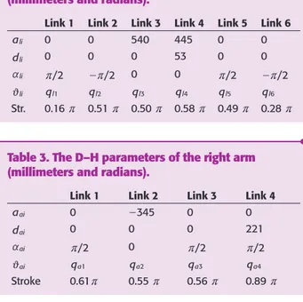
To summarize, the kinematic architecture of the BE legs is defined by the Denavit–Hartenberg parameters and joint angular strokes given in Table 2 (the data are only for the right leg; the left leg is symmetric with respect to the medi-an-sagittal plane).
Arms
With regard to the upper extremities, the BE comprises two symmetrically identical arms, each featuring two limbs (the upper arm and forearm) and a gripper. Referring to Figure 2, the upper arm is connected to the BE torso via a universal joint formed by two consecutive revolute joints J^ a1 and )Ja2
with orthogonal and intersecting axes. The upper arm is
Figure 2. The kinematic architecture of one arm and one leg of the BE (photo courtesy of the PERCRO Laboratory, TeCIP Institute, Scuola Superiore Sant’Anna).
Ja5 +G z} U Ja4 Ja3 Ja1 Ja2 Jl1 Jl2 Jl3 Jl4 Jl6 Jl5 al4 aa4 a l3 aa2 (a) BE Trunk Top View Actuator of the Joint Jl2,R
Axis of the Joint Jl2,R
Remote Center of Rotation Mechanism
Remote Center of Rotation Mechanism
(b)
Figure 3. (a) The back view of the right leg joint Jl2 showing the implementation of the remote center of the rotation mechanism and (b) the top view of a CAD representation of the mechanism and the kinematic scheme (photo courtesy of PERCRO Laboratory, TeCIP Institute, Scuola Superiore Sant’Anna).
connected to the forearm via a single revolute joint .Ja3 The
forearm is connected to the gripper via a single revolute joint .
Ja4 The gripper has 1 DoF for clamping external objects and
provides a cylindrical handle as the physical interface with the wearer’s hand.
The center of the universal joint of the BE arm is collocated with the shoulder center of a 50th percentile male wearer. The revolute axis of joint Ja1 is not parallel to the z axis of the BE
torso, but it is inclined by an azimuthal angle }a=-0 35. rad and a polar angle U =a 0 41. rad (see Figure 2). The axes of joints Ja2 and Ja3 are parallel to the wearer’s elbow
flexion/ex-tension axis, and their distance is aa2= 0.350 m. The distance
between the axis of joint Ja3 and the axis of the handle that is
grasped by the user is aa4= 0.221 m. Joints , ,J Ja1 a2 and Ja3
are used to position the gripper end-point G in space (here G is the point of intersection between the axis of the gripper handle and that of Ja4), whereas joint Ja4 provides a
controlla-ble orientation for the clamped external object around the gripper prono/supination axis. The 1-DoF gripper comprises three rigid fingers with compliant pads, with an actuated parallelogram mechanism controlling the translation of one of these fingers with respect to the other two.
Within the limits of physical realizability and system compactness, the angles }a and Ua as well
as the lengths aa2 and aa4
have been chosen to appropriately match the positional work space of the BE arm to the useful portion of that of the wearer (for the entire population of the considered human users) and
to bring the elbow singularity of the BE outside such a useful work space. Since the BE has been developed for heavy materi-al handling rather than precision manipulation, the two orien-tational DoF of the gripper in the directions orthogonal to the prono/supination axis have not been implemented. This sig-nificantly simplifies the BE architecture. Besides, in many cir-cumstances, this reduced arm mobility can be compensated by appropriate movements of the torso in the case of single-arm manipulation and by the higher pairing nature of object-grip-pers contacting elements in the case of dual-arm grasping.
To summarize, the kinematic architecture of the BE arm is defined by the Denavit–Hartenberg parameters and joint angular strokes given in Table 3 (the data are only for the right arm; the left arm is symmetric with respect to the me-dian-sagittal plane).
Mechanical Implementation
Actuation
A fully optimized actuation system for the BE should be dimen-sioned using actuators and speed reducers with properties and dimensions that are specifically designed for each joint of the robot. However, motorization of the joints of the BE is achieved by employing actuation units arranged in a modular architec-ture. In particular, the same type of electric motor is used for all of the joints. This tradeoff has been made to 1) reduce the devel-opment complexity of the system, 2) improve system reliability, 3) reduce system costs, 4) simplify maintenance, and 5) be able to produce replacement parts with reasonable costs and time. The advantage of having one type of motor for the whole robot-ic system becomes apparent in the simplifrobot-ication/reduction of 1) the driver electronics (one type of driver), 2) the mechanical components (the same bearings, bolts, and so on), 3) the equip-ment required for motor assembly (one for all the actuators), and 4) the warehouse of replacement parts.
The motor type considered for the implementation is a brushed electric motor from Axsys technologies (Mod. N. 3181-235-050), whose ratings are provided in Table 1. Brushed motors have been selected instead of the more effi-cient and lightweight brushless motors, as they were available as off-the-shelf components, with maximum ratings (force and speed) and encumbrances matching the desired ones. The motor is modularly mounted according to three main different actuation configurations (Figure 4) that employ ad-ditional mechanisms for the implementation of speed reduc-ers that are: 1) compliant with the required speed reductions and motion ranges of robot joints, 2) compliant with the little space available, and 3) fully integrated in the mechanical structure of the robot links.
Configuration A
In Configuration A, the rotational motion of the motor is first converted into a linear motion through a ball-screw drive and then reverted back to rotational by a special cable pulley sys-tem [Figure 4(a)]. The use of a novel (patented) pantograph mechanism makes it possible to drive the output torque (or
Table 3. The D–H parameters of the right arm (millimeters and radians).
Link 1 Link 2 Link 3 Link 4
aai 0 -345 0 0 dai 0 0 0 221 i a a r/2 0 r/2 r/2 i a j qa1 qa2 qa3 qa4 Stroke 0.61r 0.55 r 0.56 r 0.89 r
Table 2. The D–H parameters of the right leg (millimeters and radians).
Link 1 Link 2 Link 3 Link 4 Link 5 Link 6
ali 0 0 540 445 0 0 dli 0 0 0 53 0 0 li a r/2 -r/2 0 0 r/2 -r/2 li j ql1 ql2 ql3 ql4 ql5 ql6 Str. 0.16 r 0.51 r 0.50 r 0.58 r 0.49 r 0.28 r
The proper choice and
design of the kinematic
architecture of an FB-EHPA
is a fundamental step in
the development process.
displacement) in a bidirectional mode over a wide range of motion of the output link. This configuration makes it possi-ble to achieve a constant speed reduction ratio of 1:101 with an average mechanical efficiency of 86% (more details, in-cluding dynamic characterization of this actuation configura-tion, are reported in [19]).
Configuration A is implemented in two different sizes: 1) a high torque version in which the components are
dimen-sioned for a target output nominal torque of 500 Nm, em-ployed for the actuation of joints , , , , andJ J J Jl3 l4 l5 a1 Ja2
2) a low-torque version in which components are dimen-sioned for a target output nominal torque of 290 Nm, em-ployed for the actuation of joint .Ja3
Configuration B
In Configuration B, the rotational motion of the motor is first converted into a linear motion through a ball-screw drive and then reverted back to rotational by an inverted slider crank mechanism [Figure 4(b)]. This configuration features a non-constant speed-reduction ratio and a limited range of motion of the output. Diverse implementations, which differ in the di-mensions of crank and connecting rod, have been conceived to match the various joint requirements in terms of torque, ve-locity, and range of motion. Configuration B is employed for the actuation of joints , ,J J Jl1 l2 l6,andJa5.
Configuration C
In Configuration C, the motor is coupled with the output axis through a gear train reducer implementing a speed re-duction ratio of 1:160 [Figure 4(c)]. This is obtained through a double stage reduction with the idler gear coupled to a large-diameter hollow driven gear that surrounds the fore-arm of the user. The Configuration C is employed only for the actuation of joint .Ja4
Mechanical Design Details
The detailed design of the mechanical components of the BE has been conducted with the
aim of minimizing the over-all system mass through struc-tural optimization. A further important issue that has been considered is the mass distri-bution, which has been placed so as to guarantee stability dur-ing static walkstability dur-ing, as demon-strated in the simulation [20].
In this section, some of the relevant mechanical details of the BE are highlighted, in-cluding 1) the gripper, 2) the remote center of rotation em-ployed for the implementa-tion of the leg joints ,Jl2 and
3) the attachments to the wearer’s body.
The Gripper
The end-effector of the BE is equipped with a dual parallel jaw gripper. One of the jaws (Figures 1, 5, and 6) is fixed with respect to link 4 of the arm. Jaw movement is im-plemented through a par-allelogram mechanism that is activated by an
ac-tuator mounted according to Configuration B. The closing command is provided by a sensorized trigger lever that is con-trolled by the closing movement of the user’s hand.
Remote Center of Rotation
Joint Jl2 passes through the center of the user’s hip and is
im-plemented through the remote-center-of-rotation mecha-nism as shown in Figure 4. This allows the leg of the BE to keep adherence to that of the user, particularly during opera-tions that require the system to turn in place. This feature is especially desired when operations are conducted in nar-row spaces.
Figure 4. The CAD representation of the actuation configurations: (a) configuration A, (b) configuration B, and (c) configuration C (photo courtesy of the PERCRO Laboratory, TeCIP Institute, Scuola Superiore Sant’Anna).
Jl6 Ja4 Jl3 Ball-Screw Ball-Screw Idler Gear Pinion Driven Gear Actuator Actuator Cables (a) (b) (c) Foot Pantograph Mechanism Jl5 Jl66666 Ja44444444444444444444444 Jl3 l-Screw Ball-Screw Idler Gear Pini Driven Gear tuator Actua Foot aph smmmmmmmmm Jl5
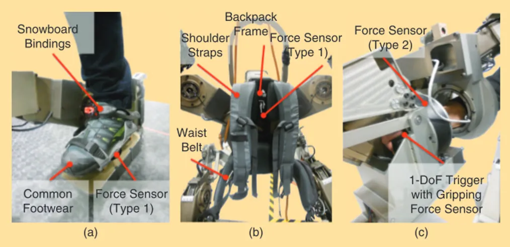
Figure 5. Solutions for connecting to the human limbs and back: (a) a snowboard binding for the foot; (b) a plastic backpack frame with shoulder straps, a lower back pad, and a waist belt for the torso; and (c) the custom-made gripping handle equipped with a trigger for the hand (photos courtesy of the PERCRO Laboratory, TeCIP Institute, Scuola Superiore Sant’Anna).
(a) (b) (c) Snowboard Bindings Backpack Frame Shoulder Straps Waist Belt Force Sensor (Type 1) Force Sensor (Type 2) 1-DoF Trigger with Gripping Force Sensor Common Footwear Force Sensor (Type 1)
The BE employs five force
sensors, one for each
contact point with the
user’s body.
Attachments
The attachments to the human body at the level of the hands, torso, and feet are particularly critical for providing comfort during operation. For the hands, a simple handle equipped
with a trigger lever (for gripper activa-tion) is implemented [Figure 5(c)]. The feet and torso attachments have been designed by employing a readjustment of available commercial systems that are already designed for a comfortable and ergonomic interaction. For the feet attachments, a pair of snowboard bind-ings have been integrated to guarantee a solid and reliable connection [Fig-ure 5(a)]. Regarding the torso, the attachment has been implemented through the parts of a framed back-pack, including the plastic frame, lower back pad, straps, and waist belt [Figure 5(b)].
Manufacturing and Materials Most of the structural components of the BE have been constructed of hard anodized aluminum alloy (Ergal 7075). The components have been machined through a high-precision CNC milling machine or lathe, except for the 12 structural shells of the actuation modules in Configuration A, which have been produced by cast molding.
Figure 6. The specifically developed force sensors based on 6-6 Stewart platform architecture. Type 1 is employed for (a) the trunk and (b) the feet, while (c) type 2 is for the hands. The force sensors are arranged to measure the interaction forces between the user and the machine and, thus, are placed between the attachments to the user’s body and the robot links (photos courtesy of the PERCRO Laboratory, TeCIP Institute, Scuola Superiore Sant’Anna).
(a) Type 1 6 # Uniaxial Load Cells Torso Force Sensor Underfoot Force Sensor (b) (c) Type 2 6 # Uniaxial Load Cells
Handle Force Sensor Parallelogram Mechanism
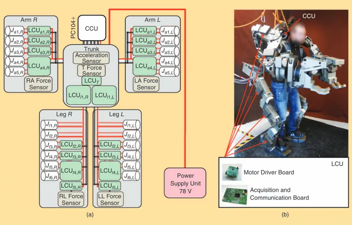
Figure 7. The global architecture of the electronics-communication structure of the BE that shows the LCUs: (a) the LCU distributed on the structure of the machine and (b) the photos of the two boards of the LCU and their physical location on the robot structure (photo courtesy of the PERCRO Laboratory, TeCIP Institute, Scuola Superiore Sant’Anna).
Trunk Acceleration Sensor T Force Sensor Arm L Arm R
Ja1,R LCUa1,R
LCUl2,R LCUl3,R LCUl4,R LCUl5,R LCUl2,L LCUl3,L LCUl4,L LCUl5,L LCUa2,R LCUa3,R LCUa4,R LCUa1,L LCUa2,L LCUa3,L LCUa4,L LCUl1,R LCUl1,L LCUT RA Force
Sensor LA ForceSensor
RL Force
Sensor LL ForceSensor
Ja2,R Ja3,R Ja4,R Ja5,R Ja1,L Ja2,L Ja3,L Ja4,L Ja5,L Jl1,R Jl2,R Jl3,R Jl4,R Jl5,R Jl6,R Jl1,L Jl2,L Jl3,L Jl4,L Jl5,L Jl6,L Leg R Leg L Power Supply Unit 78 V CCU PC104 + LCU CCU
Motor Driver Board Acquisition and Communication Board
Electronics, Sensing, and Control
Sensing
Besides the position sensing of each motor axis, which is achieved through an integrated incremental encoder (with 4,000 cpr) designed by Lika Electronic S.p.a., the BE is equipped with force and acceleration sensors. In particular, the BE employs five force sensors, one for each contact point with the user’s body (Figure 6). Each force sensor has 6 DoF measuring maximum forces and torques up to 2,500 N and 30 Nm, respectively. Two different types of sensor architec-tures have been studied and implemented. Type 1 is more compact and is conceived for sensing feet and trunk force/ torque. Type 2 is used for the hand gripper and has a hollow structure that makes it possible to host the handle that the user grasps during operation. Both types of sensors are based on six monoaxial load cells (FUTEK-LSB200-L2357-FSH00105), which are arranged according to the 6-6 Stewart-platform architecture with a semiregular hexagonal base and platforms. A further monoaxial cell is employed for sensing the gripping force exerted by the operator hand on the trigger lever.
The torso is also equipped with an acceleration sensor (ST Microelectronics, LIS3L06AL) that is employed for detecting its orientation with respect to gravity.
Electronics
The BE is equipped with onboard electronics and sensing, whereas the main power supply is currently delocalized on the ground. The scheme of the electronics, showing the main units, is reported in Figure 7. The control system is based on a distributed architecture composed by a central control unit (CCU) and 19 local control units (LCUs). The CCU is built on the standard PC104+ architecture and is composed of two CMD158886 CPU modules (dedicated separately to the con-trol of the arms and legs), two CM17212HR Dual RJ45 fast Ethernet interface peripheral modules, and one HE104+DX standard dc/dc power supply module. The CCU is located be-hind the user’s head, on the top of the torso of the BE, and is responsible for the higher-level control of the machine. LCUs are physically distributed on the arms, legs, and torso of the BE. Each LCU is composed of two specifically designed elec-tronic boards: 1) an acquisition/communication board and 2) a motor driver board. LCUs are responsible for the low-level control of the motor, the acquisition of encoders, force sen-sors, and acceleration signals. The acquisition/communica-tion board is based on the ARM7 microcontroller and is equipped with: 1) ten analog to digital converter channels, 2) four digital to analog converter channels, 3) an Ethercat slave controller, and 4) two encoder counters and ten digital input/ output. The driver board is equipped with two motor drivers (ELMO-Motion Ocarina 10/100), except for the LCUs that are commanding a single motor, which are equipped with only one driver module.
EtherCAT field bus communication has been employed to guarantee a high refresh rate with minimum complexity of the
wiring. The achieved sampling rate of the controller (in the “Control” section) is 3 kHz for the legs and 4 kHz for the arms.
With regard to the main power supply, an external unit has been chosen that is composed by 13 6-V AGM batteries (Fullriver-DC225-6) connected in series to provide a nominal working voltage of 78 V and a nominal current of 11 A. The maximum available peak current and energy storage are 3,375 A (for a duration of 5 s) and 17.5 kWh, which are well above the requirements of
the system. The battery system can guarantee the operation for 20 h with an average power consump-tion of 900 W.
Control
This section describes a preliminary controller that has been implement-ed considering a set of basic functionalities of
the BE, including: 1) full body motion while standing (squat-ting, torso rotation, and arm movements), 2) weight lifting/ handling, and 3) walking.
The development of a controller that can guarantee the full exploitation of the BE functionalities is a difficult challenge. In fact, the machine should be able to fully track the human movements while ensuring a safe and intuitive interaction. In particular, an ideal controller should be able to guarantee equilibrium in static and dynamic conditions when the ma-chine is unloaded and while it is carrying loads of different sizes and weights. In the current state, the BE is not provided with any countermeasure that automatically prevents the ma-chine from falling. The user is solely responsible for the equi-librium of the machine, and a training period is required to gain the necessary skills to drive it. However, advanced con-trol strategies that aim at guaranteeing the stable equilibrium of the system will be studied in the future.
The arm, torso, and lifted foot of the BE are controlled with a simple tracking controller that aims to minimize the
Figure 8. A schematic of the tracking controller of human limbs. CCU LCU1 LCU2 Fs T1 T2 q1m T3 Vd q.d q.1m q2m q.2m q3m q.3m + -+ -+ -LCU3 CCU LCU1 LCU2 Fs F T1 T2 TT q1mm T3 TT Vd V V qqq.d q.1m q2m q.2 q qm q3m q.3 q qm + -+ -+ -LCU3 Y(s) J-1 PI D(s) PI BE D(s) PI D(s)
The machine is the first
prototype intended as
a research platform
for studying
human-exoskeleton interaction.
interaction forces at the physical interfaces (handles for the arms, a backpack for the torso, and snowboard bindings for the feet). Such a minimization is obtained through a global force controller based on a local velocity loop at the joint level. As an example, the scheme of the controller of one arm is represented in Figure 8. The CCU sets the instantaneous value of the desired velocities at the joint level to impose a velocity at the handle that is calculated by filtering
the force reading (at the handle sensor) via user defined im-pedance Y(s) in Cartesian space. The low-level velocity con-trol is managed at the joint level by the LCU. In particular, the external force applied to the gripper is interpreted as a velocity error to be compensated. The closing of the gripper is also force controlled via a closed-loop scheme that leaves to the operator the possibility of feeling a fraction of the grasping force that the BE exerts to the manipulated object.
The control during walking is encompassed through a multistate architecture that takes into account the following working conditions: 1) a BE with two feet on the ground (State 1), 2) a BE with the left foot lifted (State 2), and 3) a BE with the right foot lifted (State 3). In all states, the grounded foot (feet) is (are) assumed to be perfectly fixed to the floor by the track-ing controller of the torso. In States 2 and 3, the torso is assumed as a reference fixed body by the tracking controller of the lift-ed foot. The transitions between states are decided on the basis of thresholds that are set both on the foot force sensor readings and on the force exerted on the floor (which is estimated from motor current readings). In particular, the foot is consid-ered and lifted as soon as the force as-sumes a positive upward value along the vertical axis; the foot is assumed to be on the ground when the vertical down-ward foot force and the estimation of the downward force exerted on the floor are simultaneously above predetermined thresholds. The states are managed with smooth transition phases implemented via weight functions. A feedforward com-ponent of gravity compensation of the self-weight of the machine is introduced irrespective of the machine state.
Experimental Tests
In this section, we report a set of func-tional tests that have been conducted with the BE to show its basic functional-ities and performances. In particular, the focus is set on the following three basic tasks: 1) walking at a low speed, 2) squatting with no load, and 3) lifting an object with one arm (Figures 9 and 10).
During the tests, the BE was secured with a nontensioned rope attached from above, which prevents the system from falling in case of a loss of equilibrium, while not interfering with the motion of the system during ordinary operation. An assistant always followed the pilot from behind, ready to shut down the power and prevent possible/accidental losses of
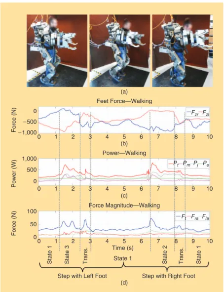
Figure 9. The (a) photos and (b)–(d) data plots captured during one full walking cycle, when no load is carried by the machine. The states of the controller are reported at the bottom of (d). (b) The vertical component (i.e., normal to the palm of the
foot) measured by the right foot ( )Fzr and left foot ( )Fzl force sensors. (c) The power
consumption of the machine; in particular: the total power consumption ( ),Pt the
estimated mechanical power ( ),Pm the power losses for Joule dissipation in actuators
( ),Pj and the stand-by power adsorbed by the onboard control electronics ( ).Pe (d) The
magnitude of forces on the torso ( ),Ft right handle ( ),Fra and left handle ( ).Fla The data
span the different phases of the walking cycle with the state transitions of the controller indicated on the bottom (photos courtesy of the PERCRO Laboratory, TeCIP Institute, Scuola Superiore Sant’Anna).
0 0 0 1 2 3 4 5 (b) (a) 6 7 8 9 10 0 1 2 3 4 5 (c) (d) 6 7 8 9 10 0 1 2 State 1 State 1 Time (s)
Step with Left Foot Step with Right Foot
State 3 State 2 State 1 Trans. Trans. 3 4 5 6 7 8 9 10 Force (N ) Power (W) Force (N ) -500 500 -1,000 1,000 0 50 100 Feet Force—Walking Fzr Ft Fra Fla Fzl Force Magnitude—Walking Power—Walking Pt Pm Pj Pe
The motor is modularly
mounted according to three
main different actuation
configurations.
equilibrium in case of abnormal functioning of the system.
Figure 9 reports the results acquired during a full walk-ing cycle performed at low speed and with no carried weight. The vertical force components measured at the feet (which are employed to trigger the state of the controller) are reported in Figure 9(b). The power con-sumption is shown Fig-ure 9(c), distinguishing 1) the total power consumption Pt
(measured at the power teth-er), 2) the mechanical power Pm (that includes mechanical
energy only), 3) the power dissipation due to Joule losses Pj (estimated via motor
cur-rents and motor electrical re-sistance), and 4) the electrical stand-by power Pe (expended
by the electronic system). Fig-ure 9(d) reports the force magnitude measured at the hands and torso.
Figure 10(a) reports the power consumption data [analo-gous to Figure 9(b)] relative to squatting with no weight. Figure 10(b) reports the power consumption data relative to the up-and-down lifting of a 26-kg mass.
As shown, the power consumption of the control electron-ics is almost task independent and is roughly equal to 120 W. The maximum registered peak power consumption is approx-imately 750 W and occurs during walking (specifically during foot rising). Irrespective of the task, a significant portion of the power consumption is due to electrical losses in the motor windings (however, these could be reduced significantly by re-sorting to high-efficiency brushless torque-motors in place of the dc motors adopted here).
As it can be observed in the plots, the machine is used at a rather slow speed. Several seconds are required to accomplish what are considered to be basic tasks. This is, of course, a limita-tion of the current system and is mainly due to: 1) the lack of ac-tive control of balance, which induces the operator to move slowly through quasi-static equilibrium conditions and 2) even if the maximum speed of the joints is acceptable, the machine could benefit from improved actuators, at least for a subset of leg joints (ankle, knee, and hip flexion).
Conclusions
A prototype of a medium- to heavy-duty FB-EHPA has been developed as a research platform for the study of shared transport and handling of heavy loads, up to 50 kg with one
arm at full horizontal extension. The one-of-a-kind system demonstrated the feasibility of a complex, electrically pow-ered FB exoskeleton with such a target payload during com-mon operating conditions in relevant laboratory settings. Be-cause of its modular hardware and open software architecture, the obtained system can easily be repro-grammed and
reconfig-ured to conduct studies on complex human-exo-skeleton interaction.
Besides the successful demonstration, the fol-lowing limitations of the current version of the system have been identi-fied during the experi-mental trials:
●
● Operator training: the machine requires
sev-eral repeated trials for acquiring the necessary skills to correctly drive it, especially due to the difficulties in maintaining the equilibrium during heavy load handling and carriage.
●
● Slow speed of the machine: The machine is quite slow
mainly due to the excessive prudence of the user, who needs to focus too much to keep the system in equilib-rium, and due to hardware limitations given by the
Figure 10. A plot of the power consumption during a single cycle of (a) squatting and (b)
handling a 26-kg cylindrical load. The charts report the total power consumption ( ),Pt estimated
mechanical power ( ),Pm power losses for Joule dissipation in actuators ( ),Pj and stand-by power
adsorbed by the onboard control electronics (Pe) (photos courtesy of the PERCRO Laboratory, TeCIP Institute, Scuola Superiore Sant’Anna).
D
D: Downward Squat R: Rising Phase S: Standing
Li: Lifting Load H: Handling Lo: Lowering Load 600 400 200 Po wer (W) 0 600 400 200 Po wer (W) 0 0 1 2 3 0 1 2 3 4 5 Time (s) Time (s) (a) (b) 4 5 6 S Pt Pm Pj Pe R S Li H Lo
The CCU sets the
instantaneous value of
the desired velocities at
the joint level to impose a
velocity at the handle.
relatively low maximum ratings of motor speed (espe-cially for the leg joints).
●
● Difficulties in bimanual manipulation: Stable bimanual ma-nipulation of loads requires more advanced controllers that consider the mutual interaction of robot arms with the object (this is particularly critical for the manipulation of stiff objects).
To address these issues, a long-term research program has been launched with the aim of developing novel control algo-rithms to 1) make the machine walk on complex/uneven ter-rains, 2) improve bimanual manipulation, and 3) optimize
power efficiency. More-over, some hardware im-provements are currently being considered, which mainly involve the intro-duction of underfoot/ gripper wrist force sensors and the substitution of the brushed motors with spe-cial designed brushless ac-tuators with improved maximum velocity and efficiency. Solutions for an onboard power supply system are also under development.
References
[1] H. Kazerooni, “Exoskeletons for human performance augmentation,” in Springer Handbook of Robotics, B. Siciliano and O. Khatib, Eds. Berlin Heidelberg, Germany: Springer, 2008, pp. 773–794.
[2] H. Herr, “Exoskeletons and orthoses: Classification, design challenges and future directions,” J. NeuroEng. Rehab., vol. 6, no. 21, pp. 1–9, 2009. [3] A. M. Dollar and H. Herr, “Lower extremity exoskeletons and active or-thoses: Challenges and state-of-the-art,” IEEE Trans. Robot., vol. 24, no. 1, pp. 144–158, 2008.
[4] R. Bogue, “Exoskeletons and robotic prosthetics: A review of recent de-velopments,” Ind. Robot: Int. J., vol. 36, no. 5, pp. 421–427, 2009.
[5] C. P. Lent, “Mobile space suit,” U.S. Patent 3 034 131, May 15, 1962. [6] N. J. Mizen, “Powered exoskeletal apparatus for amplifying human strength in response to normal body movements,” U.S. Patent 3 449 769, June 17, 1969. [7] B. R. Fick and J. B. Makinson, “Final report on Hardiman I prototype for machine augmentation of human strength and endurance,” United States Army Project No. IM62410105072, General Electr. Co., New York, DTIC Accession Number: AD0739735, 1971.
[8] T. J. Snyder and H. Kazerooni, “A novel material handling system,” in Proc. IEEE Int. Conf. Robotics Automation, Minneapolis, MN, Apr. 22–28, 1996, vol. 2, pp. 1147–1152.
[9] K. Yamamoto, K. Hyodo, M. Ishii, and T. Matsuo, “Development of power assisting suit for assisting nurse labor,” JSME Int. J. Series C, vol. 45, no. 3, pp. 703–711, 2002.
The states are managed
with smooth transition
phases implemented via
weight functions.
[10] Y. Sankai, “HAL: Hybrid assistive limb based on cybernics,” in Springer Tracts in Advanced Robotics, vol. 66, Berlin Heidelberg, Germany: Springer-Verlag, 2011, pp. 25–34.
[11] S. Toyama and G. Yamamoto, “Development of wearable-agri-robot mechanism for agricultural work,” in Proc. IEEE/RSJ Int. Conf. Intelligent Robots Systems, St. Louis, MO, Oct. 10–15, 2009, pp. 5801–5806.
[12] T. Ishida, T. Kiyama, K. Osuka, G. Shirogauchi, R. Oya, and H. Fujimoto, “Movement analysis of power-assistive machinery with high strength-amplification,” in Proc. SICE Annu. Conf., Taipei, Taiwan, Aug. 18– 21, 2010, pp. 2022–2025.
[13] S. C. Jacobsen and M. Olivier, “Contact displacement actuator system,” U.S. Patent WO 2008 094 191, Aug. 7, 2008.
[14] S. Marcheschi, F. Salsedo, M. Fontana, and M. Bergamasco, “Body ex-tender: Whole body exoskeleton for human power augmentation,” in Proc. IEEE Int. Conf. Robotics Automation, 2011, pp. 611–616.
[15] Human Factors for Designers of Equipment—Part 2: Body Size, Defence Standard 00–25, 1997.
[16] G. Zong, X. Pei, J. Yu, and S. Bi, “Classification and type synthesis of 1-DOF remote center of motion mechanisms,” Mech. Mach. Theory, vol. 43, no. 12, pp. 1585–1595, 2008.
[17] A. B. Zoss, H. Kazerooni, and A. Chu, “Biomechanical design of the Berkeley lower extremity exoskeleton (BLEEX),” IEEE/ASME Trans. Mechatron., vol. 11, no. 2, pp. 128–138, 2006.
[18] R. Riener, M. Rabuffetti, and C. Frigo, “Stair ascent and descent at differ-ent inclinations,” Gait Posture, vol. 15, no. 1, pp. 32–44, 2002.
[19] M. Bergamasco, F. Salsedo, S. Marcheschi, N. Lucchesi, and M. Fontana, “A novel compact and lightweight actuator for wearable robots,” in Proc. IEEE Int. Conf. Robotics Automation, May 2010, pp. 4197–4203.
[20] N. Lucchesi, S. Marcheschi, L. Borelli, F. Salsedo, M. Fontana, and M. Bergamasco, “An approach to the design of fully actuated body extenders for material handling,” in Proc. IEEE RO-MAN, Sept. 13–15, 2010, pp. 482–487.
Marco Fontana, TeCIP Institute, Scuola Superiore Sant’Anna, Pisa, Italy. E-mail: [email protected].
Rocco Vertechy, TeCIP Institute, Scuola Superiore Sant’Anna, Pisa, Italy. Email: [email protected].
Simone Marcheschi, TeCIP Institute, Scuola Superiore Sant’Anna, Pisa, Italy. E-mail: [email protected]. Fabio Salsedo, TeCIP Institute, Scuola Superiore Sant’Anna, Pisa, Italy. E-mail: [email protected].
Massimo Bergamasco, TeCIP Institute, Scuola Superiore Sant’Anna, Pisa, Italy. E-mail: massimo.bergamasco@ sssup.it.