ALMA MATER STUDIORUM-UNIVERSITA DI BOLOGNA
SCUOLA DI INGEGNERIA E ARCHITETTURA
Corso di Laurea Magistrale in
Ingegneria dei Processi e dei Sistemi Edilizi
Curriculum Historic Building Rehabilitation
APPLICATIONS OF ADDITIVE MANUFACTURING IN CONSTRUCTION
AND HISTORIC BUILDING RESTORATION / REHABILITATION
Tesi di Laurea Magistrale in Research on Historic Building M
Relatore Presentata da
Prof. Ernesto Antonini Fuat Emre Kaya
Correlatori
Prof. Michele Palermo
Prof. Marco Pretelli
Anno Accademico 2019/2020
I
Abstract
The term “Additive Manufacturing” is described as the layered production of parts from a 3D file. Over the past century, this technology has evolved from a complement tool for conventional product development into an independent production method. Whereas high technology industries such as aerospace and medicine were already embraced additive manufacturing, structural engineering and architecture are lagging. Additive manufacturing has the potential to revolutionize the construction and restoration of historic buildings, with foreseeable benefits including highly complex and efficient structures with the reduction in material use and wastage, streamlining and expedition of the design-build process, improved customization. However, there are also challenges and demands: a new way of thinking for design and verifications for stability and serviceability of printed elements, the cost, the need for well-educated engineers.
In this dissertation, the current state of additive manufacturing in construction and historic building restoration/rehabilitation is reviewed as a combination of qualitative and quantitative-based studies. The research aims to give confidence to additive manufacturing applicability in these fields and stimulate further research. The opportunities and challenges are discussed by analysing concrete, polymer, and metal-based processes and their applications of additive manufacturing in the construction sector. A review of structural and non-structural applications in restoration projects, possible future applications in terms of structural strengthening are analysed and opportunities and challenges are identified and discussed. Based on the literature review and experimental lab tests, the outcome was obtained as the tensile mechanical properties are adequate for structural engineering applications. However, further interdisciplinary research on additive manufacturing is necessary to build confidence in structural engineers and architects.
II
Acknowledgements
Even though the master’s thesis is based on individual academic research, I could not arrive at the end of it without the help and guidance of many people.
Firstly, I want to express my gratitude to my thesis supervisor Prof. Ernesto Antonini. His knowledge, guidance, and insightful comments challenged me to get the best out of myself. Furthermore, I am very grateful to Prof. Michele Palermo for guiding me through the unfamiliar territory of wire and arc additive manufacturing. My sincere thanks to Prof. Marco Pretelli, for his expert insight into the restoration and conservation of historic buildings, and all the time he invested.
I am indebted to the generosity of Vittoria Laghi, who supported me in my internship even in the hardest periods of quarantine.
My sincere thanks to my mother Dr. Aysegul Tanriverdi Kaya, and to my father Prof. Dr. Murat Kaya who are always inspired me to pursue my career in the academic direction. Moreover, I would like to thank my sister Zeynep Sila Kaya for her love and support.
I want to thank Gorkem Muslu, Cansu Samsun, Esra Nur Eda Kucuk, and Pelin Kesim. Their infinite support and love were always with me.
I want to thank Enrico Cardillo, Maria Samareva, Zelan Li, Luisa Hammond, Remzi Mert Polatcelik, Berfin Tutku Ozcan, Ulker Basak, and Bensu Berk for their patience, kindness, and love. Finally, I want to thank my flatmate, Elisabetta Antonino for making me feel at home.
III
Content
Abstract ... I Acknowledgements ... II Chapter 1 - Introduction ... 1 1.1 Motivation ... 11.2 Methodology and Approach... 1
Chapter 2 - Additive Manufacturing Technologies ... 3
2.1 Definition of Additive Manufacturing ... 3
2.2 Generic Process of Additive Manufacturing ... 3
2.3 Milestones in Additive Manufacturing ... 5
2.4 Classification of Available Technologies ... 6
Material Extrusion ... 6
Powder Bed Fusion ... 7
Vat Photopolymerization ... 8
Binder Jetting ... 9
Material Jetting ... 10
Sheet Lamination ... 10
Directed Energy Deposition... 12
IV
Chapter 3 - Additive Manufacturing in Construction ... 14
3.1 Additive Manufacturing of Concrete Elements in Construction ... 14
3.1.1 Concrete Additive Manufacturing Techniques and Strategies ... 15
Material Extrusion ... 15
Concrete Printing (3DCP) ... 16
Existing 3DCP Manufactured Structural Elements ... 16
a) Wonder Bench ... 16
b) 3D Printed Concrete Columns (Concrete Choreography) ... 18
c) Acoustic Damping Wall Element ... 19
Contour Crafting (CC) ... 20
Existing Contour Crafting Manufactured Structural Elements ... 20
a) 3D Printed Concrete Castle ... 20
b) 3D Printed Structures by Winsun ... 21
c) The Concrete Wall and The Hollow Wall... 23
Powder Bed Fusion ... 24
D-Shape ... 24
Existing D-Shape Manufactured Structural Elements ... 25
a) Castilla La Mancha 3D Bridge ... 25
b) One Single Process Printed House (La Casa Tutta di Un Pezzo) ... 26
3.1.2 Comparison Between Existing Techniques in Large Scale Construction ... 27
3.1.3 Opportunities and Challenges of Concrete Additive Manufacturing in Construction ... 28
Opportunities ... 28
a) Design Flexibility ... 28
b) Construction Cost and Time ... 29
c) Environmental and Social Impact ... 30
Challenges ... 30
a) Size of The Printer ... 30
b) Cementitious Material Compatible with 3D Printer ... 30
V
d) Reinforcement Implementation ... 31
e) Printing Precision and Efficiency ... 31
3.1.4 Discussion ... 31
3.2 Additive Manufacturing for Polymer-Based Materials in Construction ... 32
3.2.1 Polymer Additive Manufacturing Techniques and Strategies... 32
Material Extrusion ... 32
Big Area Additive Manufacturing ... 32
Existing BAAM Manufactured Structural Elements ... 33
a) AMIE ... 33
Other Examples of Large-Scale 3D-Printers of Polymer Extrusion ... 35
a) Kamermaker ... 35
b) The Digital Construction Platform (DCP) ... 36
Powder Bed Fusion ... 37
Existing SLS Manufactured Structural Elements ... 37
a) Polymer Cladding on Metal Connections ... 37
3.2.2 Opportunities and Challenges of Polymer Additive Manufacturing in Construction ... 38
3.2.3 Discussion ... 38
3.3 Additive Manufacturing of Metal Elements in Construction ... 39
3.3.1 Metal Additive Manufacturing Techniques and Strategies ... 39
Powder Bed Fusion ... 39
Existing PBF Manufactured Structural Elements ... 40
a) Nematox Façade Node ... 40
b) Arup Lighting Node ... 40
Directed Energy Deposition (DED) ... 44
Wire and Arc Additive Manufacturing ... 44
Existing WAAM Manufactured Structural Elements ... 44
a) The MX3D Bridge ... 44
b) MX3D Takenaka Connector ... 45
VI
Opportunities ... 47
a) Design Flexibility and Optimization of Material Properties ... 47
b) Mass Customization ... 47
c) Structural Strengthening and Repair ... 48
Challenges ... 48
a) Anisotropic Behaviour and Residual Stress ... 48
b) Standards and Tests ... 48
c) Cost ... 48
3.3.3 Discussion ... 50
Chapter 4 - Additive Manufacturing in Restoration ... 52
4.1 Possible Non-Structural and Structural Applications of Additive Manufacturing in Historic Building Restoration ... 53
4.1.1 Non-Structural Applications ... 53
Rapidly Forming a Prototype ... 53
a) Reproduction of a Gothic Arch ... 53
b) Reproduction of Stone Pedestal (Plinth) of a Historic Column ... 54
Rapidly Forming a Mould + a Prototype ... 55
a) Modern Ornamental: A New Form of Digital Structure ... 56
b) Comparative Analysis on Reproduction of Eclectic Ornament ... 58
4.1.2 Structural Applications ... 60
a) 3D Printed Formwork for Erecting Vaulted Covering ... 60
b) Democrite Wall ... 60
4.2 Potential Applications ... 62
a) In Situ Repair and Restoration ... 62
b) Infrastructure Repair ... 62
c) More Elaborated Techniques in Moulding ... 62
4.3 Risks and Opportunities of Additive Manufacturing in Restoration ... 63
VII
Chapter 5 - Literature Review and Laboratory Test Data ... 65
5.1 Literature Review ... 66
5.2 Laboratory Data and Their Calibration ... 68
5.2.1 Calibration of Design Values Based on Best-Fit Statistical Distribution ... 69
5.2.2 Calibration of Design Values Based on Eurocode 0 ... 72
Results ... 74
Conclusions ... 75
1
Chapter 1
Introduction
1.1 Motivation
Additive manufacturing (AM) technologies have been developing over the past three decades, and today 3D printers have become as common as 2D printers. This technology allows the building of objects efficiently and with reduced material waste. AM provides a significant level of geometric and material freedom; thus, virtually any desired shape can be designed and produced without being restricted to standard elements. This feature can reconsider standard construction parts like joints, I-beams, or other construction materials. According to Strauss (Strauss 2013), "AM technology even allows us to engineer
the parts integrally; for example, the functionality of a hinge could be derived from the material properties rather than from fittings, bolts, and joints added to the part. Additive methods allow for structures that are not realizable with the traditional manufacturing methods. AM can integrate complex functions into components without additional work expenditure. No longer taking place at the construction site, the assembly does in the virtual model". (p.21) 1. However, not all the construction parts or materials are possible or cost-effective to be produced by AM. For this reason, AM's possible applications are many, but some of them are still very challenging and not yet suitable for widespread application. Much research has been performed to implement AM in the construction industry successfully. However, only very few AM applications target the restoration field. This dissertation aims to discuss AM's opportunities in the construction sector and explore its applicability in the restoration of historical buildings.
1.2 Methodology and Approach
This thesis combines qualitative and quantitative-based studies; the data is obtained from reliable published sources and tests carried in the laboratory.
Following this first introductory chapter, Chapter 2 describes the current state of AM. The Chapter defines AM and describes AM's generic process step by step from the CAD file generation to the final physical model. The developments in AM throughout history are also discussed as well as its current state. A classification of the AM available technologies is finally drawn up, pointing out and discussing each class of processes' features and benefits.
2 Chapter 3 focuses on AM in the construction sector, analysing concrete, polymer, and metal-based processes, as they are the most utilized for applications in the field. A review of the existing concrete, polymer, and metal AM technologies is provided, then each of them is analysed with special regards to their implications within the building sector. Finally, opportunities and challenges are identified and discussed.
The main topic of Chapter 4 is AM in the restoration of historic buildings, especially rehabilitation of historic buildings, to strengthen structural elements. A qualitative approach is adopted due to a lack of available and reliable data sources regarding this topic. A review of possible structural and non-structural applications is provided, and potential applications are analysed, then opportunities and challenges are identified and discussed.
Chapter 5 adopts a quantitative approach by providing the results of a lab test campaign on specimens of metallic building elements shaped by the AM wire and arc technique. Brief information on the wire and arc additive manufacturing (WAAM) is provided. A comparison is then made for the mechanical properties (yield, ultimate strength, and modulus of elasticity) of conventionally and WAAM produced metal specimens. The data for the conventional and additive manufactured elements are derived from the literature review. Additionally, the detailed data issued from lab tests regarding the 0°, 10°, and 45° tensile properties of WAAM produced metal specimen are provided. The main output is to identify the level of strength and modulus of elasticity that WAAM can achieve, aiming at assessing its suitable applicability in the construction and restoration field.
This thesis in structural engineering and architecture explores the AM in building construction and restoration, aiming to encourage AM applications in these fields and stimulate further research.
3
Chapter 2
Additive Manufacturing Technologies
This chapter aims to introduce basic additive manufacturing concepts and generic manufacturing processes from design to application. It continues to discuss the developments in additive manufacturing throughout history and its current state. The chapter concludes with the classification of additive manufacturing technologies and their benefits.
2.1 Definition of Additive Manufacturing
Additive manufacturing is a term used to describe rapid prototyping or, more commonly, 3D printing. Rapid prototyping is used in various software, management, and manufacturing fields to define the rapid manufacturing process or part of the product before its release. However, rapid prototyping is no longer adequate to describe the new technologies developed in this field. For this reason, a Technical Committee within ASTM international has adopted the term additive manufacturing, aiming to better cover the widening use of rapid prototyping techniques and its permeation across various industrial sectors.
According to ISO/ASTM 52900(2015), additive manufacturing (AM) is defined as a "process of joining
materials to make parts from 3D model data, usually layer upon layer, as opposed to subtractive manufacturing and formative manufacturing methodologies" (p.9) 1. This technology's basic principle is to fabricate a three-dimensional computer-aided design model (3D CAD) directly by avoiding planning and making a multi-step process. Therefore, the additive manufacturing process can be considered an alternative technique to the conventional manufacturing process, which involves moulding and shaping an object by subtractive processing.
2.2 Generic Process of Additive Manufacturing
AM involves many steps from virtual CAD description to a final physical model (Fig.1). In this part, each of these steps is explained. As shown in Table 1, the main steps are the CAD model's generation, the transformation of the CAD file to the acceptable format, file transfer to the machine, machine setup, the building of desired objects, object removal, post-processing, and application 1. However, the process can be grouped or broken down to adapt to each case, and evolve with new technologies, while still following the same general order 2.
1 ISO/ASTM 52900:2015, 2017
4 Figure 1: Additive Manufacturing Stages 1
Table 1: Generic Process of Additive Manufacturing 13
Step Name Stage Output
Generation of CAD model of design A 3D solid representation of external geometry Converting of CAD file to STL format STL format of the external closed surface of the
object
STL file transformation to machine Transferred STL format with corrections of the file in terms of dimension, orientation, and position
Machine setup Setup regarding energy source, energy constraints, and layer thickness
Build Built desired object Removal of object Removed object
Postprocessing Cleaning of the surface of the removed object Application Additional treatment
The first step is the description of the external geometry of the output. External geometry can be provided using CAD solid modelling software or reverse-engineering equipment like laser and optical scanning to obtain 3D solid or surface representation. A representative output of CAD modelling software is illustrated in Figure 2.
5 The CAD model must then be converted to STL format, which describes the object's external closed surfaces. It provides the basis for the slice calculation. Figure 3 illustrates a representative object as converted to STL format from CAD.
Figure 3: Representative CAD (Left) AND STL Image (Right) 1
In the next step, the STL file should be transferred to the additive manufacturing machine, and manipulation of files is done to achieve the correct size, position, and orientation after the transfer. Then machine setup in terms of energy source, energy constraints, and layer thickness should be performed. When the setup of the machine is completed, the build process of the desired object can start. Build process is taken care of automatically by the machine itself without any supervision. However, the machine's superficial monitoring should be done based on ASTM F42 to ensure no errors occur. As soon as the build process finishes, the final model can be removed from the machine, and the post-processing step can start. This step aims to clean the produced object before it is acceptable for use. Within the last step, called application, the produced and cleaned objects may require an additional treatment like priming or painting to make the surface have a certain texture and finishing.
2.3 Milestones in Additive Manufacturing
The concept of AM can be traced back to the 1860s when two-dimensional photos were used to produce three-dimensional sculptures 3. Research efforts have resulted in the development of the concept of proof and patents. In the 1960s, photopolymerization was invented, and in the 1970s, powder bed fusion and sheet lamination for ceramics, metals, and polymers were developed 4. In the late 1980s, the first commercialized additive manufacturing technology, stereolithography (Fig.4), was invented by Charles Hull 1. New AM technologies started to increase rapidly in the 1980s when the number of both publications and filed patents recorded a strong increase 5. For example, laminated object manufacturing (LOM) was patented in 1986 by Helisys; in the same year, Cubital patented solid ground curing, and DTM patented selective laser sintering (SLS). However, only selective laser sintering remains commercial today 1. Moreover, fused deposition modelling (FDM), also called material extrusion, and the 3D printing process, also known as binder jetting, have been patented by different companies in
3 Gao, Zhang, Ramanujan, Ramani, Chen, Williams, Wang, Shin, Zhang, Zavattieri, 2015
6 1986. In the 1990s and 2000s, AM continued to evolve with other commercialized technologies such as electron beam melting 5. In 2005, the RepRap project developed the first AM machine suitable as a personal usage hobby, thanks to the easy dissemination of information resulting from internet development 5. AM technologies and their products are used in various fields today, such as product manufacturing, energy, transportation, medicine, and the construction sector, including restoration.
Figure 4: First Commercialized Technology with Stereolithography found by Hull 1
There have been numerous failures and successes in the history of AM, but according to Gibson (2016), "some of them may have failed due to poor business models or poor timing, not because of poor process" (p.38) 1. An attempt to categorize AM has been made by ISO/ASTM 52900, which identifies seven key groups of technologies: binder jetting, directed energy deposition, material extrusion, material jetting, powder bed fusion, sheet lamination, and vat polymerization 5.
2.4 Classification of Available Technologies
The seven key groups of AM based on ISO/ASTM 52900 are discussed in the following paragraph, while the specific technologies used in construction and restoration are expanded upon in Chapters 3 and 4.
Material Extrusion
ISO/ASTM 52900(2015) defines material extrusion as an "additive manufacturing process in which
material is selectively dispensed through a nozzle or orifice" (p.10) 2. In other words, it deposits the layers with a mechanically extruded molten thermoplastic material, mainly ABS (Acrylonitrile Butadiene Styrene) or PLA (Polylactic Acid), onto a substrate 1456.
5 Buchanan, Gardner, 2019
6 Loughborough University. Additive Manufacturing Research Group. Retrieved from
7 The first layer should be built as nozzle deposits material, and then the following layers should be added layer by layer (Fig.5). Finally, layers are integrated during a deposition when the material is still in the melted state 1 4 5 7. The material extrusion process is operated at high temperatures; thus, the final product may exhibit high porosity 1457.
This process's advantages are inexpensiveness and flexibility. Besides that, the thermoplastic materials, especially ABS, are easily accessible and provide good structural properties. However, accuracy and speed are low compared to other systems 1457.
Figure 5: Material Extrusion Process Illustration 1 Powder Bed Fusion
According to ISO/ASTM 52900(2015), powder bed fusion is an "additive manufacturing process in
which thermal energy selectively fuses regions of a powder bed" (p.11) 2.
The most popular powder bed fusion technologies are direct metal laser sintering, selective laser melting, and electron melting. In these technologies, after scanning of a layer, the subsequent layer is spread by using a rolling mechanism and fused to the previous layer (Fig.6). During the procedure, a high temperature is required to sinter the structural powder fully 1457.
8 Advantages of the process are its inexpensiveness and a large variety of material options. Even though powder bed fusion mainly uses powder-based material, common metals such as stainless steel, titanium, aluminium, cobalt chrome, and polymers can also be used 14 57. However, the main disadvantage of this process is its slow speed 1457.
Vat Photopolymerization
According to ISO/ASTM 52900(2015), vat photopolymerization is an "additive manufacturing process
in which liquid polymer in a vat is selectively cured by light-activated polymerization" (p.11) 2. In this process, a liquid polymer resin is used to construct the model layer by layer. The resin is cured and hardened using ultraviolet light while the object is constructed downward on the moving platform. The layers are continually constructed and cured until the model is complete.
Two main configurations and one additional configuration have been developed for the vat photopolymerization process 1. These configurations are vector scan approach, mask projection approach, and two-photon approach (Fig. 7). One of the main differences in these three configurations is that the vector scan and two-photon approaches utilize a scanning laser beam, while the mask projection approach utilizes a radiation beam. Furthermore, photopolymerization occurs in the intersection point of two laser beams in the two-photon approach, while the other two approaches use just one laser beam and different photopolymerization concepts. Unlike the other two approaches, the two-photon approach makes the recoating unnecessary; thus, it is faster than the other two approaches 1. However, resin discharge from the vat and final model removal after completion is obligatory and common in these three approaches.
9 Overall, the vat photopolymerization process is relatively quick, and it provides high-level accuracy, good finishing, and it can be used for typically large build areas. However, it uses particularly UV curable polymer resin, which is expensive to be supplied, and requires unbound material support since there is no structural support from the material itself 1457.
Binder Jetting
According to ISO/ASTM 52900(2015), binder jetting is defined as an "additive manufacturing process
in which a liquid bonding agent is selectively deposited to join powder materials" (p.10) 2. Binder jetting was developed at MIT, and the original name was three-dimensional printing 1. During the process, the first layer is built by spreading powder material using a roller over the build platform. Then, binder adhesive is deposited by using the print head over the powder. The liquid from the binder acts as an adhesive to bond the powder form. Once the first layer is finished, the platform should be lowered down, then the deposition of the subsequent layers follows the same procedure (Fig.8) until the final model is achieved. However, postprocessing is needed to remove the final product model from the powder bed and remove unbound powder by using pressurized water. Finally, the printed final model requires infiltration to gain sufficient strength since it is composed of bound powder.
Figure 8: Binder Jetting Process 1
A wide range of composite polymers (ABS, PA, PC), metals (stainless steel), and ceramics can be used in this system 1457. Additionally, support structures are not needed since the parts are self-supporting 14 57. Binder jetting process is faster than the other processes, and the use of two different materials can result in different combinations of binder-powder, different mechanical properties, and different colours 1 457. However, this process may not be appropriate for the structural parts depending on the binder type used 1457.
10 Material Jetting
According to ISO/ASTM 52900(2015), material jetting is defined as an "additive manufacturing
process in which droplets of feedstock are selectively deposited" (p.11) 2. In the material jetting process, droplets of the material are released by a nozzle that moves horizontally along the building platform, and then droplets are cured through photocuring or heating (Fig.9). The same process continues with the further layers by building them subsequently. As a final step, the layers are left to harden and cured using ultraviolet light, then support material should be removed as a postprocessing step.
This process can only use the materials that can be deposited in drop form such as polymers and waxes, meaning only a limited number of materials can be utilized 1457. High accuracy can be achieved thanks to the usage of droplets 1457. However, this process requires a support.
Figure 9: Material Jetting Process Illustration Sheet Lamination
According to ISO/ASTM 52900(2015), sheet lamination is defined as an "additive manufacturing
process in which sheets of material are bonded to form a functional element that could constitute all or a section of an intended product" (p.10) 2. The sheet lamination process has two technologies: laminated object manufacturing (LOM) and ultrasonic additive manufacturing (UAM). Laminated object manufacturing is one of the first commercialized technology. Layer by layer lamination of paper material sheets are cut by using a carbon dioxide laser, and each sheet is represented as a cross-sectional layer of CAD model. This technology uses the cross-cutting method, in which the paper sheet is sliced into cubes, to remove the final element easily (Fig.10).
11 Figure 10: Sheet Lamination (Laminated Object Manufacturing) Process 1
Laminated object manufacturing helps to achieve low internal tension and low fragility of elements. It provides high surface finish details and machines, and it can be considered inexpensive due to the low cost of the process, material, and machine.
Ultrasonic additive manufacturing involves bonding the metallic sheets by ultrasonic welding, CNC milling, and removing unbound metal parts (Fig.11). The object parts are constructed from bottom to top on a base plate bolted on a heated plate during the process. Each layer contains several metal foils laid side by side, and layers are trimmed using CNC milling.
Figure 11: Ultrasonic Additive Manufacturing Process 1
Ultrasonic additive manufacturing does not require high temperature. Generally, the temperature is not required to be higher than 50% of the melting temperature of the joined metals 1457. Thus, thermally induced internal stresses and deformations are not a major problem; in fact, the technology allows for internal geometries 1457.
12 Directed Energy Deposition
According to ISO/ASTM 52900(2015), directed energy deposition is defined as an "additive
manufacturing process in which focused thermal energy is used to fuse materials by melting as they are being deposited" (p.10) 2. In other words, directed energy deposition's working principle is based on creating the new model by melting the material as it is deposited 1. This process is predominantly used for metal powders, but also ceramics and polymers can be utilized. For this reason, the technique can be called "metal deposition technology."
A typical directed energy deposition machine (Fig.12 (a)) contains a nozzle located on a multi-axis arm, enabling the nozzle to move in different directions. The multi-axis arm works as structural support to build complex three-dimensional objects. Metallic powder or wire is generally used as a feedstock material. A laser beam, an electron beam, or a plasma arc is used as an energy source.
Figure 12: (a) Directed Energy Deposition Machine (Left) 1, (b) Directed Energy Deposition Process (Right) 1
During the production process of directed energy deposition, wire or powder material is deposited using the multi-axis nozzle on the surface. Then, the deposited material is fed into the energy source's focal point to create a molten pool (Fig.12 (b)). The process continues layer by layer until the final model is achieved.
Directed energy deposition machines enable the production of complex three-dimensional objects directly from CAD files, unlike conventional welding and cladding technologies 1 4 5 7. Another advantage of this process is that it can be used to repair and maintain structural parts. As a result of the local melting and rapid cooling, the resultant microstructure becomes well-refined; the resultant parts have high density and strength. Attained strength can be 30% higher than the ones produced with casting 6. Furthermore, this process can add coatings to an existing structure to increase the tribological performance of structural elements 6. However, limited material usage and postprocessing applications, such as milling of the final product surface, are considered disadvantages of this technology 1457. A summary of the main points of each additive manufacturing technology, including the materials, advantages, and disadvantages, is provided in Table 2.
13 Table 2: Additive Manufacturing Classification of Technologies 4
2.5 Discussion
Even though there are still challenges regarding the AM process, it provides advantages over traditional additive manufacturing 1457. It is seen as a more precise way to predict the time required to produce the object and speed the cutting, forming, and casting process 1457. It also reduces the material waste; thus, the production cost 1457.
Categories Technologies Stamped Material Power Source Adv. Disadv.
Material Extrusion Fused Deposition Modelling
• Thermoplastics • Ceramics • Metals
Thermal Energy • Inexpensive cost • Multi-material usage • Limited part resolution • Poor surface finish Contour Crafting
Powder Bed Fusion Selective Laser Sintering Polyamides/polymers A high-powered laser beams. • High accuracy • High density and strength • Support structure need Direct Metal Laser Sintering Metals Selective Laser Melting Electron Beam Melting
Electron beam • High density and strength Vat Photopolymerization Stereolithography • Polymer • Ceramics Ultraviolet Laser • High Speed • High resolution • High Cost
Material Jetting Polyjet/Inkjet Printing
• Photopolymer
• Wax • Thermal Energy • Photocuring • Multi-material printing • High surface finishing • Low-strength material
Binder Jetting Indirect Inkjet Printing
• Polymer powder • Ceramic powder • Metallic powder
Thermal energy • Full-colour object • Wide material selection • Infiltration of the final object • The high porosity of the final object
Sheet Lamination Laminated
Object Manufacturing
• Plastic film • Metallic sheet • Ceramic tape
Laser beam • High surface finish • Low cost • De-cubing issues Directed Energy Deposition Laser Engineered Energy Shaping
Molten metal powder Laser beam • Repairment of damaged parts • The functionality of graded metal printing • Requirement of postprocessing Electronic Beam Welding
14
Chapter 3
Additive Manufacturing in Construction
The chapter consists of three main parts outlining concrete, polymer, and metal additive manufacturing processes in the construction sector. Their features and characteristics are presented and discussed within the chapter, aiming to clarify the suitable technologies and strategies, the opportunities, and challenges for their application in th e specific field.
Additive manufacturing applications in construction varies from a single structural element such as walls and columns to completely 3D printed buildings and bridges by using different technologies and materials.
3.1 Additive Manufacturing of Concrete Elements in Construction
Concrete is one of the most utilized materials in construction thanks to its low cost and worldwide availability of its raw materials. Concrete elements can be shaped by different techniques such as pouring on-site, offsite pre-casting, spraying, or tilt-up. However, most current techniques require formworks and moulds in which the concrete is shaped when poured inside in the fluid state. Especially for on-site casted concrete, the formwork placing and tearing down accounts for 35 to 60 % of the element production cost 123. In construction, only simple geometries with a constant cross-section are mostly used; thus, formworks can be re-used, and formwork cost can be minimized 4 5. However, additive manufacturing does not involve the use of formwork, and it brings several potential advantages such as lower labour cost, the possibility of more complex element geometries, reduced construction time, high accuracy, and less material wasting. The additive manufacturing process of concrete elements is a layer-based manufacturing technique allowing the freeform construction 23. Historically, the first attempt to print concrete elements was made by Pegna in the late 1990s 678. He presented the freeform construction idea in which a layer fabricated concrete element by layer selective deposition of cement. The later developed technologies in construction are discussed in the following section.
1 Buchanan, Gardner, 2019
2 Kreiger E., Kreiger M., Case, 2019 3 Rael, Fratello, 2018
4 Lowke, Dini, Perrot, Weger, Gehlen, Dillenburger, 2018 5 Le, Austin, Lim, Buswell, Gibb, Thorpe, 2012
6 Lim, Buswell, Le, Austin, Gibb, Thorpe, 2012 7 Buswell, Soar, Gibb, Thorpe, 2007
15
3.1.1 Concrete Additive Manufacturing Techniques and Strategies
In recent years, AM has been developed to meet the demand in construction and architecture. Currently, the AM process targeted at large-scale building elements mainly includes three types: Concrete Printing and Contour Crafting, which both adopt the material extrusion process, and the D-shape method, which applies the powder bed fusion process.
Material Extrusion
The material extrusion process has been explained in Chapter 2, while concrete extrusion is addressed here. The concrete extrusion method (Fig. 13) enables creating an element layer of fresh cementitious material by a nozzle that deposits it along the defined path. Specific requirements for both fresh and hardened concrete must comply so that a high quality of printed elements can be ensured. To perform a successful printing process, possible particle segregation must be prevented so a blockage in hose and nozzle (pumpability) can be avoided, the easy extrusion of cementitious material into layer must be allowed (extrudability), as well as the superposition of multiple layers (buildability) 569. Besides that, material and process-related parameters, admixtures, and printing head should be chosen carefully.
Figure 13: Concrete Extrusion Process 59
According to Paolini (Paolini 2019), "concrete extrusion processes can be divided into three based on
the filament size. These are deposition of fine filaments with less than 1 mm, deposition of medium-sized filaments with cross-sectional dimensions up to several cm, and deposition of coarse filaments in the range of several dm" (p.2) 9. 3D Concrete Printing (3DCP), Contour Crafting, and CONPrint3D, which are the most utilized concrete extrusion techniques, belong respectively to the three-subgroups mentioned above. However, in this dissertation, only Concrete Printing and Contour Crafting are discussed under the material extrusion part, as they are the AM technologies mainly used in construction and architecture.
16 Concrete Printing (3DCP)
Concrete printing (Fig.14) is a large-scale process used in construction, based on concrete extrusion done by a print head with three-dimensional moving freedom, which is mounted on an overhead crane. The fresh concrete is delivered to a pump through a deliver pipe, then to the nozzle via the pump. The nozzle so deposits fresh concrete to form the desired structural element.
Figure 14: Illustration of Concrete Printing with the Deposition System 8
The deposition resolution is low, but this feature causes a high control over complicated geometries 68. For this reason, 3DCP has the potential to be used in the manufacturing of structural elements.
Existing 3DCP Manufactured Structural Elements
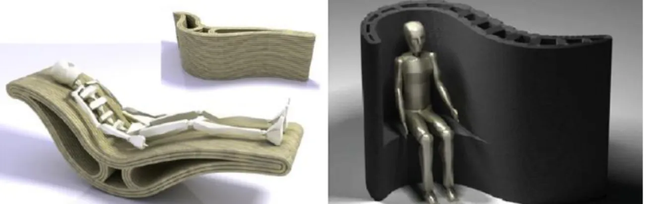
a) Wonder Bench
A curved shape wall-bench element with a dimension of 2.0 x 0.9 x 0.8 meters was designed using 3DCP technology by Loughborough University. The 3D model of the wall-bench can be seen in Figure 16. A total of 128 layers of the wall-bench element were printed layer by layer in approximately 42 hours with a 20 min/layer printing speed.
17 The wall-bench has a smooth surface front with a seat and a backside with a square wave superimposed on the surface (Fig. 16).
Figure 16: Final Form of Wall-Bench
The top layer partially hides the 12 functional white-coloured voids of the internal structure and their reinforcements (Fig. 17) and having different sizes and shapes to follow the element's curve geometry. The voids' main purpose is to minimize the element weight and provide it acoustic and thermal insulation performances and space to house technical installations 6. Besides that, there are 23 grey-coloured voids in which 8 mm reinforcing bars have been inserted.
Figure 17: Internal Structure with Functional Voids and Reinforcements
According to Lim (Lim 2011), "This approach offers a simple, workable method of incorporating
tensile capacity into large cement-based components, demonstrating the potential for automated manufacture of large construction components" (p.6) 6. The wonder bench has been presented in two international exhibitions, as the main purpose of this wall element with a curved bench was to show the possibilities of additive manufacturing compared to conventional techniques 5.
18 b) 3D Printed Concrete Columns (Concrete Choreography)
The design and fabrication of these columns were performed at ETH Zurich. The research's main aim was to investigate a new concrete typology, thus demonstrating remarkable architectural qualities achievable through 3DCP 10. The procedural computational design engines based on trigonometric functions and mesh subdivision were developed and utilized (Fig.18) 10.
Figure 18: Trigonometric Functions and Mesh Subdivision 10
Each column has been designed as a composition of a double shell and an internal bracing (Fig.19) 10. The outer shell is sized in a range of 0.25 m to 0.6 m, with an ornamental exterior, and the inner shell was designed as a cavity for traditional reinforced concrete. In each layer, these shells were connected with internal bracing. The internal bracing supports the adjacent layers, provides a closed core and increases the overhang for column geometry 10.
Figure 19: Double Shell Composition and Internal Bracing 10
19 Trigonometric functions were used to design highly differentiated ornaments on the external shell. Moreover, the characteristic dripping behavior of concrete has helped to subvert the horizontal layer of aesthetics. This behavior was used to create a dramatic effect at column capital and base to distinguish them from the shaft by emphasizing their ornamental purpose 10. In the fabrication stage, columns were printed in 2.5 hours/column printing speed. In the end, a total of 9 columns with a total height of 2.7 m were fabricated in ten weeks 11.
c) Acoustic Damping Wall Element
The acoustic damping wall element (Fig. 20) was designed and manufactured by C.Gosselin in France for structural and acoustic purposes. A total of 26 layers of the element were printed layer by layer in approximately 2 hours with a 4.6 min/layer speed. It contains different hole geometries providing soundproofing properties by damping the acoustics waves 11.
Figure 20: Acoustic Damping Wall Element
20 Contour Crafting (CC)
Contour Crafting is a large-scale process used in construction, based on concrete extrusion done by a multi-axis deposition head to fabricate large objects with dimensions of several meters 67 8. Contour Crafting offers high-speed production in construction scale, a wide range of utilized materials, and good quality surface finish 678. According to Buswell (Buswell 2006), "More recently, Contour Crafting has
been demonstrated to produce large (>1 m) structures. In essence, the process produces a replacement for the structural concrete block wall commonly used in UK house construction" (p.4) 7.
Contour Crafting combines extrusion and filling. Two trowels are installed on the printing nozzle, and then the printing nozzle starts to move in the pre-defined path to print the external edges. After that, another cementitious paste fills inside the internal volume, which is created by outer edges. The construction process is illustrated in Figure 21.
Figure 21: Illustration of Contour Crafting with the Deposition System8
This technology currently leads the construction field, and it has been successfully applied in on-site applications.
Existing Contour Crafting Manufactured Structural Elements
a) 3D Printed Concrete Castle
Andrey Rudenko has designed, and 3D printed a concrete castle with dimensions of 15 m2 in Minnesota/USA. It consists of three towers and walls which surround the castle. The parts were printed separately and assembled into one single structure (Fig. 22). The concrete castle is life-size and capable of habitation.
Rudenko (Rudenko 2014) states that" it is possible to print limitless amounts of classical décor as well
as brand new elements and shapes, whereas previous technology made innovative constructions difficult and expensive." 12
12 Azzarello, 2014. Andrey Rudenko constructs 3D printed concrete castle in Minnesota. Retrieved October 19,
2020, from https://www.designboom.com/technology/3d-printed-concrete-castle-minnesota-andrey-rudenko-08-28-2014/.
21 Figure 22: 3D Printed Concrete Castle 12
b) 3D Printed Structures by Winsun
One of the leading Chinese advanced material suppliers, Winsun Decoration Design and Engineering Company, after their research in AM invented a printing nozzle and an automatic material feeding system in 2005. Their experience in the construction industry helped them to become an architecture firm with innovative additive manufactured constructions. In 2014, the company constructed a set of ten single-story residential buildings in under 24 hours 13. The residential buildings (Fig. 23 (a)) were printed firstly as panels with a cement-based mixture containing construction waste and glass fiber, then printed panels were assembled on-site. Then, electrical systems, insulation, and plumbing were added to all buildings. Moreover, in 2015 the company constructed the tallest 3D printed building with five stories (Fig. 23 (b)) and a complete mansion of 1.100 m2, including external and internal decorations (Fig. 23 (c)). Both of these structures were constructed using a cement-based mixture 13. In 2016, the company constructed the first additive manufactured office (Fig. 24) 13. The office building walls were printed separately with a cement-based mixture containing reinforced glass fiber, and then the printed parts were assembled and transferred to Dubai 13. Buchanan states that the office building reduced 80% of the construction cost, 60% of labor cost, and produced 60% less waste material than a conventionally manufactured building 1.
22 Figure 23: (a) First 3D Printed Residental Building (Shown in Top Left),
(b) 3D Printed Five-Story Apartment (Top Right), (c) 3D Printed Mansion (Bottom)
23 c) The Concrete Wall and The Hollow Wall
Behrokh Khoshnev has designed and printed a concrete wall, with dimensions of 1.52 x 0.61 m, using a cement paste. Firstly, the external wall has been extruded, and then concrete was manually poured incrementally with one-hour intervals to complete the wall (Fig. 25). Furthermore, in 2013, Khoshnev has designed and fabricated a wall with a corrugated internal structure with a cement paste (Fig. 26).
Figure 25: 3D Printed Wall by Contour Crafting
24
Powder Bed Fusion
The powder bed fusion process has been explained in Chapter 2, while the concrete powder bed process is addressed here. The powder bed fusion process is an AM deposition process for fabricating automatically large-scale free-form structures. The principle consists of creating a dry particle layer and then selectively depositing fluid to make the dry particles bond. These two repetitive steps continue until all layers are completed. As a final step, loose particles are removed, and heating or infiltration may be required as postprocessing. In contrast to the material extrusion process, the powder bed fusion process allows more design freedom because of mechanically stable dry-packed particles. For example, inclined structures, overhangs, suspended beams, arches, and vaults can be fabricated easily 4. However, construction space is more limited due to being filled with dry particles, but it provides high resolution and possible high accuracy even under 0.1 mm 9.
D-Shape
D-shape is a large-scale 3D printer with 300 nozzles and a 6 m wide printing head to print objects up to 6 m in width 69. The printing head can move freely in the x-direction along the horizontal beam and in the z-direction along the vertical beams through four stepper motors, as is shown in Figure 27.
25 Existing D-Shape Manufactured Structural Elements
a) Castilla La Mancha 3D Bridge
The Castilla La Mancha bridge (Fig. 28) is the first 3D printed pedestrian bridge located in the urban park of Castilla La Mancha in Alcobendas, Madrid/Spain. Institute of Advanced Architecture of Catalonia directed the bridge's fabrication, and the project was completed in 2 months. The bridge was built using the powder bed fusion process utilizing concrete powder and polypropylene reinforcement. The structure consists of eight portions with a dimension of 2x2 m, and it has a total span of 12 m and a width of 1.75 m 11415.
Figure 28: Castilla La Mancha 3D Printed Pedestrian Bridge
14 Valencia, 2017, World's First 3D Printed Bridge Opens in Spain. Retrieved October 23, 2020, from
https://www.archdaily.com/804596/worlds-first-3d-printed-bridge-opens-in-spain.
15 3D printed bridge. (2020, April 20). Retrieved October 23, 2020, from
26 The bridge construction was designed to optimize the distribution of materials and minimize waste material by recycling raw material during manufacture 11415. The design process also allowed using generative algorithms to maximize the structural performance 1.
b) One Single Process Printed House (La Casa Tutta di Un Pezzo)
The building with dimensions of 2.4x4.0x3.5 m (Fig. 29) has been designed by Marco Ferreri and printed based on powder bed deposition of cement paste in one shot in three weeks. It consists of four walls and a roof, and it is composed of free space for a bathroom, bedroom, and kitchen. After the fabrication, the structure was presented in the Triennale Museum of Milan/Italy; currently, it is located in Marco Ferreri's property in Milan.
27
3.1.2 Comparison Between Existing Techniques in Large Scale Construction
The techniques in large-scale construction and architecture, namely Concrete printing, Contour crafting, and D-shape, were described in the above section. These three large-scale AM techniques have similarities in how they fabricate the components in an automotive and layer-by-layer manner, but each has unique features, results, and applications. Table 3 provides a summary of the similarities and differences between these three large-scale AM techniques.
Table 3: Similarities and Differences in Large Scale AM Techniques in Construction and Architecture
Concrete Printing Contour Crafting D-Shape
Process Extrusion based Extrusion based Particle-based
Support A second material Lintel in horizontal Unused powder
Printing Resolution 9-20 mm 15 mm 0.15 mm
Layer Thickness 5-25 mm 13 mm 4-6 mm
Print Head 1 1 300
Nozzle Diameter 9-20 mm 15 mm 0.15 mm
Printing Speed Slow Fast Slow
Printing Dimension Limited scale by frame Mega scale Limited scale by frame
During the AM process, support may be required to carry the weight of the overhanging part of the 3D object. Contour crafting can fabricate vertical elements in compression without any need for a support structure, while in the horizontal direction, it needs a lintel to be placed in a gap right above the doorways or windows and walls. Even though the cantilever problem can be solved in this way, contour crafting cannot fabricate a structure with windows and roof all at once 8. In contrast, D-shape uses surrounding unconsolidated materials to support the object. Thus, D-shape prints an object within a single process 8. In comparison, Concrete Printing requires support using a second material. However, this feature results in a disadvantage since it requires an additional deposition device and postprocessing operation for secondary support structure 6.
28 Contour crafting uses a single and large diameter nozzle that prints a whole layer with two deposition head passes. Therefore, it has a higher printing speed and minimized operating time, but it has low printing resolution and large layer thickness. In comparison, D-shape uses multiple nozzles with a small diameter, which prints an entire layer by a single transverse. For this reason, this feature results in a lower printing speed but having a higher printing resolution and small layer thickness. Concrete printing uses a single and large diameter nozzle like Contour crafting. However, it limits the operating speed because it needs to transverse the whole build area. Therefore, it has a low printing speed and long operating time, low printing resolution, and large layer thickness due to single and large diameter nozzles.
Contour crafting can fabricate mega-scale structural elements by multi-axis robotic arm compared to Concrete Printing and D-shape, in which the mechanical frame limits the printing scale.
As a final comparison, Contour crafting does not require further postprocessing steps since the deposition head allows surface finishing and smoothing during the production. While in the other two techniques, printed surfaces may be required to post-process in terms of surface polishing and grinding. Each of the discussed techniques utilizes different methods and processes and results in different construction industry opportunities and challenges.
3.1.3 Opportunities and Challenges of Concrete Additive Manufacturing in Construction
Additive manufacturing of concrete elements is an innovative and promising tool for real-life large-scale constructions. However, although AM has many opportunities in the industry, there are still some challenges.
Opportunities
a) Design Flexibility
Layer manufacturing technique of AM results in new opportunities for constructing structures without formworks and shaping of materials. This feature gives an unlimited power to design complex geometries that can improve functionality. For instance, as in the case of wonder bench and acoustic damping wall elements, different shaped and sized voids can be added to achieve acoustic features, air conduits, or even wiring conduits. New geometric forms can be obtained, like in the Winsun Dubai office and Castilla La Mancha 3D bridge.
29 b) Construction Cost and Time
AM techniques offer overall cost reduction by reducing the amount of time, materials, and labour needed. AM applications accelerate the construction process. According to GuoWei (GuoWei 2017), "The building process takes a quarter of the time required to build an equivalent structure with
traditional means." (p.15) 8. Besides that, even though expensive raw materials and equipment used in AM may cause a higher construction cost, AM can still reduce material cost. Compared to conventional techniques, lower material usage resulted in decreased material consumption and produced less waste material 8. Moreover, the use of waste material and recycling of unused material is another parameter that reduces the material cost 1. In terms of labour cost, it reduces the labour requirement in construction and its cost since it offers an automated construction system. Camille (Camille 2016) performed a cost comparison between traditional and additive manufacturing techniques in terms of wall construction from 40 MPa concrete, as is shown in Table 4, by assuming the cost of formwork as %30-60 of the total cost 16.
Table 4: Cost Estimates for Construction a Wall from 40 MPa Concrete Using Traditional Method and 3D Printing 816
Conventional Manufacturing Additive Manufacturing
Cost Amount Price Cost Amount Price
Concrete Supply $200 m3 150 m3 $30000 $250 m3 150 m3 $37500 Pumping $20 m3 150 m3 $3000 $20 m3 150 m3 $3000 Labor $20 m3 150 m3 $3000 Formwork $100 m3 1500 m3 $150000 Total $186000 $40500
As Table 4 states, labour and formwork costs are almost reduced to zero using additive manufacturing. Moreover, with additive manufacturing, the total cost can be reduced to almost a quarter of that of conventional manufacturing based on the data presented.
30 c) Environmental and Social Impact
There are a series of advantages of AM over traditional manufacturing in terms of environmental and social impact. 3D printing can produce almost zero waste materials due to 3D printers having an electrically powered machine without any emission. Besides, it also reduces noises created by construction.
Challenges
a) Size of The Printer
Nowadays, AM applications at large-scale constructions are limited to structural elements or low-rise buildings because the size of the 3D printer restricts the scale of a structure that could be built 8. The innovation of mega-scale 3D printers for cementitious material continues to develop and expands the technique's applicability at a construction scale.
b) Cementitious Material Compatible with 3D Printer
Compatible cementitious material used in 3D printing should have all the properties of fresh cement: easy-pumping, easy-flowing, easy-deposition, dimension stability, and low shrinkage coordinate the printing system. Cementitious material, or concrete, can be modified by controlling the fresh properties through chemical admixtures, deposition, and printing speed so that cementitious material can be effective printing material with sufficient flowability, extrudability, buildability, and strength. However, printing material has become different from the conventional cementitious material due to the types of raw materials and admixtures, and 3D printed structures have become more expensive than conventional ones. For this reason, further research is necessary for AM concrete to find a cheap and easy solution.
c) Standards and Tests
Evaluation standards and tests for traditional concrete can no longer be suitable for additively manufactured concrete and concrete structures since the composition of printing cementitious material are quite different from the traditional ones. For this reason, new regulations and standards are required to measure and assess mechanical properties depending on the chosen feedstock, printing process, and parameters. Additionally, the development of simulation models for long-term service life prediction and structural behaviour for 3D printed concrete structures is necessary 89.
31 d) Reinforcement Implementation
3D printed concrete is brittle and weak in tension like casted concrete. Despite fiber reinforcement improving ductility and crack control, improved tensile behaviour cannot be achieved by fiber reinforcement. However, Contour crafting can solve the problem by inserting steel reinforcements using multiple arms during construction 8. Concrete printing can create different shapes with different-sized voids. Steel reinforcements are placed inside the voids so that the tensile capacity of concrete can be improved 8.
e) Printing Precision and Efficiency
Printing precision can be defined as the smallest element that can be fabricated by a 3D printer, and it is directly proportional to printing accuracy and inversely proportional to printing speed. However, even though an increase in printing precision increases printing accuracy, it decreases the construction efficiency and increases the final cost. Therefore, this relation between printing precision and the other factors should be considered well so that maximum performance of 3D printing can be achieved 8.
3.1.4 Discussion
Additive manufacturing of concrete elements is a promising and innovative technique that may change the conventional construction processes and methods 189. There are several possible applications for the future, such as integrating 3D Printing with Business Information Modelling (BIM) to reduce printing time and repeatable delivery path. Besides that, the collaborative study of NASA and ESA on a research project uses lunar material in the application of planetary construction by using Contour crafting and D-shape 9 17. Even though concrete additive manufacturing technology still faces some problems regarding the size of the printer, reinforcement implementation, compatible cementitious material, standards, tests, and printing precision, these challenges can be tackledwith further research to focus on the interdisciplinary area between material science, architecture, and civil engineering 18 9 17.
32
3.2 Additive Manufacturing for Polymer-Based Materials in Construction
Polymer-based material additive manufacturing is one of the most common additive manufacturing techniques since it combines low cost, low density, widespread equipment availability, and unlike concrete additive manufacturing, it enables storage in a controllable, ready to be used state 11819. The polymer AM techniques are the vat photopolymerization method with stereolithography, material extrusion method with fused deposition modelling process, powder bed fusion method with selective laser sintering, and binder jetting method. Different polymer materials are suitable for different methods: stereolithography utilizes liquid polymers, thermoplastics such as ABS, PLA are generally used by fused deposition modelling process and binder jetting, and thermoplastic polyamide 12 is used in selective laser sintering.
Additive manufacturing of polymer elements has been discovered in various applications, from aerospace engineering to medicine. The construction sector uses it to generate structural models, facades, and mechanical and electrical systems by architectural companies. However, many 3D printed polymers are generally used as conceptual prototypes since they cannot be used in heavily loaded parts due to their low stiffness and strength as a result of voids in printed parts 1 18 19. However, various methods such as material extrusion and powder bed fusion processes and advanced polymers with improved mechanical properties such as carbon-reinforced ABS (CF-ABS) have been developed to increase the construction sector's effectiveness.
3.2.1 Polymer Additive Manufacturing Techniques and Strategies
Material Extrusion
The material extrusion process has been explained in Chapter 2, while the polymer extrusion process is addressed here.
Big Area Additive Manufacturing
Big area additive manufacturing (Fig. 30) is a large-scale 3D printer developed by OAK Ridge National Laboratory for thermoplastics and composite materials. The BAAM can produce large polymer components with dimensions up to 6.0x2.4x1.8 m, which is almost ten times larger than most commercial techniques 920.
18 Ghaffar, Corker, Fan, 2018
19 Ngo, Kashani, Imbalzano, Nguyen, Hui, 2018
33 Figure 30: Big Area Additive Manufacturing System
In the BAAM system, the pelletized thermoplastic feedstock is melted, and melted material is deposited in thick beds of melted thermoplastic material along the path by using a single-screw extruder. With this technology, feedstock cost can be decreased by 20 times, build volumes can exceed 28.3 m3, and deposition rate, which can exceed 41.000 m3 per hour, can be increased almost 200 times compared to conventional polymer AM systems 1 20 21. The BAAM printed elements have been investigated in terms of strength and stiffness, and results show that BAAM products can be utilized for certain limited-stiffness applications in construction 22.
Existing BAAM Manufactured Structural Elements
a) AMIE
As a result of the Additive Manufacturing Integrated Energy Project (AMIE), which is performed by collaboration between the US Department of Energy's OAK National Laboratory and architectural company SOM, a cylindrical-single floor building (Fig. 31), which is the world's largest polymer 3D printed structure has been fabricated 2123. The structure has a footprint of 19.5 m2 and a height of 2.8 m, and it contains ring-like segments in the interior section (Fig. 32).
21 Biswas, Rose, Eikevik, Guerguis, Enquist, Lee, Love, 2016 22 Compton, Post, Duty, Love, Kunc, 2017
23 3D Printed Building from Polymer for Off-Grid Living: SOM, 2020 Retrieved November 06, 2020, from
34 Figure 31: Additive Manufacturing Integrated Energy Project
The segments were printed as half-rings with carbon fiber-reinforced acrylonitrile butadiene styrene (CF-ABS) by using BAAM. More than 6 tons of CF-ABS have been used, and printing took almost 225 hours 9. After that, printed half-ring segments have been assembled to form a full ring shape, and then they have been joined with four steel roads along the direction of the building (perpendicular to the printing plane of the segments). The structure consists of half ring-shaped eleven major, nine interior segments, and two end walls (Fig.32).
Each printed C-shaped segment aims to constitute the building envelope and act as a surface membrane and ensure moisture protection and isolation within the structure 2123. Apart from that, low strength and stiffness in the building direction (z-axis) of segments due to partial cooling of the extruded polymer were solved using the four steel roads along the length of structure 9.
35 Other Examples of Large-Scale 3D-Printers of Polymer Extrusion
a) Kamermaker
The ongoing polymer additive manufactured canal house (Fig. 33(a, b)) has started in Amsterdam/ Netherland in 2014 by DUS Architects. The company has been using its own 6 m tall large-scale 3D printer, which is called KamerMaker. The 3D printer can fabricate the 2.2x2.2 x3.5 m propylene blocks with 180 kg weight using the principle of extruding layers of molten biodegradable plastics 124. The project is aimed to be "zero waste" since all the blocks of it can be recycled, and the individual parts of the canal house will be completed on-site so that transportation cost can be eliminated 125. Exploded isometric view of the canal house is illustrated in Figure 33(c). The final structure will be a design museum with a footprint of 700 m2, and it will be able to be disassembled, transported, and reassembled at another location.
Figure 33: (a) Section of the Final Canal House (Top Left), (b) A 3D Printed Canal House Model, (c) Isometric View of the Canal House
24 DUS, 2013, Work. Retrieved November 06, 2020, from https://houseofdus.com/work/. 25 Hager, Golonka. Putanowicz, 2016
36 b) The Digital Construction Platform (DCP)
The DCP is a 3D large-scale printer based on the extrusion of polymer-based materials created by the Massachusetts Institute of Technology. It consists of an extrusion nozzle controlled by a 6-axis robotic arm attached to a 5-axis hydraulic arm mounted on a mobile platform (Fig. 34) 926.
Figure 34: The Digital Construction Platform
A polymeric dome (Fig.35) with 14.6 m diameter and 3.5 m height was constructed in 13.5 hours 926. The dome has been constructed by using a two-component polyurethane closed-cell form.
Figure 35: The Dome Constructed by DCP
26 Keating, 2016, Project Overview ' Digital Construction Platform. Retrieved November 06, 2020, from