A
A
l
l
m
m
a
a
M
M
a
a
t
t
e
e
r
r
S
S
t
t
u
u
d
d
i
i
o
o
r
r
u
u
m
m
–
–
U
U
n
n
i
i
v
v
e
e
r
r
s
s
i
i
t
t
à
à
d
d
i
i
B
B
o
o
l
l
o
o
g
g
n
n
a
a
DOTTORATO DI RICERCA IN
INGEGNERIA STRUTTURALE ED IDRAULICA
Ciclo XXIV
Settore Concorsuale di afferenza: 08/B2 – SCIENZA DELLE COSTRUZIONI Settore Scientifico disciplinare: ICAR/08
NONDESTRUCTIVE EVALUATION OF CONCRETE
COMPRESSION STRENGTH BY MEANS OF
ARTIFICIAL NEURAL NETWORK (ANN)
Presentata da: MARIO BONAGURA
Coordinatore Dottorato
Relatore
CHIAR.MO PROF. ING. ERASMO VIOLA PROF. ING. L
UCIO NOBILE
Table of Contents
TABLE OF CONTENTS
Abstract I
Chapter 1. Italian Standards and guidelines 1
Sommario 1
1.1 Introduction 2
1.2 Evolution of the Italian technical standards for constructions 4
1.3 Plan of investigation 9
1.3.1 Definition of the survey program 9
1.3.2 Historical analysis and collection of the original project 9
1.3.3 Execution of in-site inspections 11
1.4 Evaluation of existing buildings with NTC 2008 12
1.4.1 Levels of knowledge (KL) 12
1.4.2 Geometry (carpentry) 16
1.4.3 Construction details 18
1.4.4 Material characteristics 20
1.4.5 Factors of confidence (FC) 21
1.5 NDT methods in Italian standards for construction 21
Chapter 2. Non-destructive testing (NDT) for the evaluation of concrete 25
Sommario 25 2.1 Introduction 26 2.2 Covermeter survey 29 2.2.1 Generality 29 2.2.2 Normative references 30 2.2.3 Scope 31
2.2.4 Test equipment and applications 32
2.3 Rebound Hammer test 35
Table of Contents
2.3.2 Normative references 36
2.3.3 Scope 37
2.3.4 Test equipment and applications 39
2.3.5 Principal drawbacks 40
2.3.6 Interpretation of results 41
2.4 Ultrasonic Pulse Velocity test 42
2.4.1 Generality 42
2.4.2 Normative references 44
2.4.3 Scope 45
2.4.4 Test equipment and applications 46
2.4.5 Principal drawbacks 49
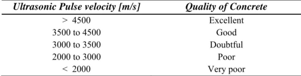
2.4.6 Interpretation of results 50
2.4.7 Concrete compressive strength evaluation by means of UPV 51
2.5 Combined method SonReb 52
2.4.1 Generality 52
2.4.2 Regression analysis 53
2.4.3 Most reliable formulation 55
Chapter 3. Artificial Neural Networks (ANN) 57
Sommario 57
3.1 Introduction 58
3.2 State of the art 60
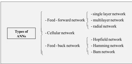
3.3 Structure of artificial neural networks 63
3.3.1 Feed-Forward Network (FFN) 65
3.3.2 Cellular Neural Network (CNN) 66
3.3.3 Feed-Back Network (FBN) 67
3.4 Activation function 68
3.5 Type of learning 70
3.6 Backpropagation error algorithm (BPE) 72
Chapter 4. Results and Analysis 75
Table of Contents
4.1 Introduction 76
4.2 Comparison between UPV methods - ANN(UPV) 77
4.2.1 Analysis with UPV methods 77
4.2.2 Analysis with ANN(UPV) 80
4.3 Comparison between SonReb methods - ANN(SonReb) 100
4.3.1 Analysis with SonReb combined methods 100
4.3.2 Analysis with ANN(SonReb) 104
Conclusions 125
Conclusions I
Abstract
The evaluation of structural performance of existing concrete buildings, built according to standards and materials quite different to those available today, requires procedures and methods able to cover lack of data about mechanical material properties and reinforcement detailing. This issue is more relevant when seismic zones are concerned and structural strengthening needs to prevent failures due to earthquakes. Recent seismic codes give relevance to procedure and methods to establish the performance levels of existing structures. To this end detailed inspections and test on materials are required. It is recognised that different levels of knowledge(KL) can be reached depending on available technical design reports, structural drawings and material acceptance data. As a consequence tests on drilled cores are required; on the other end, it is stated that non-destructive testing (NDT) cannot be used as the only mean to get structural information, but can be used in conjunction with destructive testing (DT) by a representative correlation between DT and NDT.
The aim of this study is to verify the accuracy of some formulas of correlation available in literature between measured parameters, i.e. rebound index, ultrasonic pulse velocity and compressive strength (SonReb Method). To this end a relevant number of DT tests and NDT tests has been performed on many school buildings located in Cesena (Italy). The above relationships
II Abstract have been assessed on site correlating ND test results to strength of core drilled in adjacent locations.
Nevertheless, concrete compressive strength assessed by means of NDT methods and evaluated with correlation formulas has the advantage of being able to be implemented and used for future applications in a much more simple way than other methods, even if its accuracy is strictly limited to the analysis of concretes having the same characteristics as those used for their calibration. The above limitation warranted a search for a different evaluation method for the non-destructive parameters obtained on site. To this aim, the methodology of neural identification of compressive strength is presented. Artificial Neural Network (ANN) suitable for the specific analysis were chosen taking into account the development presented in the literature in this field. The networks were trained and tested in order to detect a more reliable strength identification methodology.
Chapter 1. Italian Standards and guidelines 1
Chapter 1
Italian Standards and guidelines
Sommario
Il patrimonio edilizio in cemento armato, realizzato in gran parte tra gli anni ‘60 e ‘70, rappresenta ad oggi oltre il 50% del patrimonio ad uso abitativo. Il raggiungimento dei 40 anni di servizio per una struttura in cemento armato rappresenta il superamento di una soglia al di sopra della quale si rendono necessari controlli. In questo discorso generale sul patrimonio edilizio nazionale, non si deve dimenticare che larga parte del territorio è a rischio sismico (l’OPCM n°3274 del 2003 ha portato il numero il numero dei comuni classificati come sismici dal 37% al 58% dei comuni italiani) e solo una parte degli edifici in tali aree è stato progettato utilizzando criteri antisismici. Le Norme Tecniche per le Costruzioni (NTC 2008) suddividono il patrimonio edilizio italiano in due grandi raggruppamenti: edifici nuovi ed edifici esistenti. Per la valutazione degli edifici esistenti la normativa italiana consente di assumere, nelle verifiche di sicurezza, un adeguato valore del fattore di confidenza in base al livello di conoscenza acquisito della struttura analizzata. Per la scelta del tipo di analisi e dei valori dei fattori di confidenza vengono definiti i tre livelli di conoscenza seguenti (NTC, 2008): LC1 Conoscenza Limitata; LC2 Conoscenza Adeguata; LC3: Conoscenza Accurata.
Gli aspetti che definiscono i livelli di conoscenza sono: la geometria; i dettagli strutturali e i materiali.
2 Chapter 1. Italian Standards and guidelines
1.1
Introduction
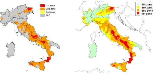
The safety of existing buildings is a fundamental task in Italy if we consider on the one hand the seismic vulnerability of our territory and on the other hand the high value of our historical, architectural and artistic heritage. A recent research carried on by Censis (Centro Studi Investimenti Sociali) has showed that the reinforced concrete buildings, built mostly between the 60s and 70s, represents nowadays more than the 50% of the Italian housing heritage. The 40 years service for a reinforced concrete structure represents the overcoming of a threshold that makes necessary specified controls. In this situation, we have not to forget that all the Italian territory is classified as seismic zone (OPCM n. 3274 of 2003 has changed the number of cities classified as seismic from 37% to 58%) and only a part of the buildings has been designed using seismic criteria.
Fig. 1.1: Comparison between seismic zoning: on the left side the first seismic zoning based on seismic hazard studies (until 1984) and on the right side the new one (introduced by OPCM n. 3274 in 2003).
Chapter 1. Italian Standards and guidelines 3 The Technical Standards for Construction (NTC 2008) subdivided the Italian building heritage into two groups: new buildings (projected in accordance with seismic criteria) and existing buildings. It is defined existing building the one that has, to the date of drafting the safety evaluation or project, the structural frame fully realized.
The logic process of evaluation and seismic adaption can be summarized into 5 main phases:
1. Knowledge of the structure (i.e. geometry, mechanical characteristics of structural materials and their conditions);
2. Definition of performance requirements (i.e. seismic risk of the site, intended use and level of seismic protection required/accepted); 3. Evaluation of the existing structure (i.e. definition of the model
study, seismic analysis and safety verification);
4. Project of seismic structure improvement (in relation to existing constraints and performance requirements);
4 Chapter 1. Italian Standards and guidelines
1.2
Evolution of the Italian technical standards for constructions
In order to better understand the character of the new Italian technical standards (NTC 2008), we should make a brief state of the art of the evolution time of the national technical standards for construction. Unfortunately the main character role in this evolution is covered by the elevated number or earthquakes over the years that have imposed many reflections on this field.
Before the unification of Italy, following the earthquake of 1783 in Calabria, (which caused about 30,000 casualties), the government of the "Kingdom of the Two Sicilies" adopted a regulation which made reference to the reconstruction rules for selecting sites on which to rebuild, the types of structural and construction details. In 1859, after the earthquake of Norcia, the Papal States issued strict rules to norm the phase of reconstruction (they set the characteristics of the foundation, maximum height of buildings and building materials). Following the earthquake of Messina and Reggio Calabria in 1908 (evaluated as the most catastrophic earthquake occurred since the unification of Italy with the death of almost 90,000 people), Royal
Decree April 18, 1909 n. 193 was issued.
The latter one listed a few hundred of cities in Sicily and Calabria in which was placed the obligation to respect the technical standards introduced by the Royal Decree (R.D.) for the construction or repair of buildings. Since this R.D., it was inaugurated the seismic classification of the territory and was started the production of norms that would follow the further development of science and structural engineering. Over the next 30 years, the Italian
Fig. 1.2: The first seismic zoning in Italy (Calabria Region)
Chapter 1. Italian Standards and guidelines 5
Fig.1.3: The relationship between Royal Decrees and seismic events.
standards were focused again on seismic hazard and few other aspects. The Ministerial Decree of
October, 30, 1912 approved the rules
for testing and acceptance of timber materials for buildings constructed by the Ministry of Public Works. The Royal Decree of July, 25, 1913
n. 998, dealt with the hygienic
standards in the construction of major public works. The Legislative
Decree (L.D.) n. 1526 of 1916, has
quantified the seismic forces and their distribution along the height of the building. The Royal Decree of December, 31, 1923 n. 3046 was focused on "standardization of
materials that can be used by the administrations of the Italian State" while
the R.D. of two years later (August, 7, 1925 n. 1616) was issued to regulate testing of electrical equipment in constructions. The successive Royal
Decree n.431 of 1927 has classified the territory as seismic, introducing two
levels of seismicity: high (1st zone) and moderate (2nd zone) on the basis of the observed damages and the subsequent seismic forces in each of them.
The R.D. n. 640 of 1935 represented, in many ways, a great step forward,
with the enactment of specific technical guidelines and the requirement for municipalities to adopt their own building codes. Furthermore, the evaluation of the overall behavior of frame structures was required for the first time according to the theory of hyperstatic elastic systems.
Since 1962, with the approval of the Act n. 1684 has provided that the seismic standards should be adhered to in the "cities subject to intense seismic activity" and not just in "cities affected by the earthquake". Despite all, nothing had changed from the previous practice of classify only as a
6 Chapter 1. Italian Standards and guidelines result of earthquakes. The next two laws passed during the 1970s represent the first standards nationally imposed. The Act n.1086 of November 5, 1971 regulates the reinforced concrete, prestressed and steel structures. The Act n.
64 of 1974, represents a milestone in the way of evolution of the actual
legislation. In fact, it has allowed an easier successive upgrade of the standards, giving to special Ministerial Decrees (M.D.) the task to regulate, in terms of security, the different sectors of construction. This innovative decision providing an easier upgrade later in the standards. For this reason, in the following years, technical standards for buildings, bridges, dams and foundations were produced without having to issue new law. It was also introduced, for the first time, a particularly incisive system of verifications and repression of violations. Between the end of 1970s and the first years of 1980s1, a need to rationalize the seismic classification of Italian territory was felt. In fact, it was not homogeneous in its distribution due to its nature evolved by successive aggregations of cities affected by earthquakes. The
Decree of the Ministry of Public Works of July 14, 1984 represents the latest
in a series of decrees in the first years of 1980s which have been reshaped the limits of seismic classification that are still partially in force.
During the next 20 years, a series of decrees who tries to adjust all the more important aspects of building were approved. The Ministerial Decree of
December, 12, 1985 approved the technical standards for piping. The
Ministerial Decree of November, 20, 1987 regulates the planning, execution
and testing phases of masonry buildings and their consolidation while the
Ministerial Decree of December, 3, 1987 regulates the prefabricated
buildings. The following year, the Ministerial Decree of March, 11, 1988 analyzes geological and geotechnical aspects. The Ministerial Decree of
May 4, 1990 regulates the planning, execution and testing phases of road
bridges. This leads to the Ministerial Decree of January, 16, 1996 that
1
After the catastrophic Irpinia Earthquake in 1980 (3500 deaths), the Italian Government issued a research group to continuously update the knowledge about seismic hazard: the National Group Against Earthquakes, GNDT (by the Italian National Research Council, CNR).
Chapter 1. Italian Standards and guidelines 7 represent the latest version of the technical standard on the calculation, construction and testing of concrete, prestressed and steel structures. The latter decree also indicates the general criteria for verifying safety of structures, loads and overloads.
Italian technical standards for constructions were deeply innovate in March 2003 with the approval of the Order of the President of the Council of
Ministers (OPCM) n. 3274 2. The aims of this ordinance was to collect and summarize all the rules concerning different aspects of building design, and adjust the general and technical construction criteria for the design, implementation and testing phase of ordinary and special buildings (such as bridges, dams, aqueducts, etc..), as well as to classify the entire national territory according to the seismic hazard. The OPCM. n. 3274 also radically changes the theoretical basis on which the previous legislation was based on construction. The main point of reference becomes the Eurocodes, for which still retains many differences. The basic concept introduced by the Ordinance3 is the Capacity Design System. This method asserts that the structures designed according to the new standards have margins of resistance that enable them to resist without collapse to seismic actions higher that of the project ones. Subsequently, the Parliament has promulgated the Decree-Law of May 28, 2004, n. 136, in which it has been settled seismic and hydraulic technical standards for construction, as well as the establishment of technical standards for the design, construction and adjustment of dams, bridges and the work of foundations. In the same decree was agreed that the priorities for actions must be ensured for school and sanitary buildings. Therefore, in order to implement the Decree-Law n. 136, was approved the Ministerial Decree of September 14, 2005 that issued
2
Immediately after the earthquake of October, 31, 2002 which hits the territories between Molise and Puglia, the Civil Protection adopted this ordinance, in order to provide an immediate response to the need to update the seismic zoning and earthquake standards.
3 The ordinance n. 3274 has been subjected to numerous and significant corrections, made
mostly with the OPCM n. 3316 of October, 2, 2003, the OPCM n. 3379 of November, 5, 2004 and the OPCM n. 3467 of October, 13, 2005.
8 Chapter 1. Italian Standards and guidelines the technical standards for construction. The aim of this M.D. was to bring together into a single technical text related to the design and construction and at the same time achieving the standardization and rationalization. This Ministerial Decree represented a complete development of the complex legislation of constructions, in relation to both structural design and the main civil engineering works and materials characteristics. It represented also a substantial update of the national legislative framework, previously based on the fundamental laws n. 1086/71 and n. 64/74.
Due to both complexity and inapplicability of some parts and continuous updating of coefficients and benchmark parameters of the last decree, the
Ministerial Decree of January 14, 2008 was approved. Nowadays this
decree, together with the applicative circular approved in April 2008, represent the latest version of the technical standards for constructions (NTC). The new NTC issued in 2008 introduce several significant changes about the responsibilities assigned to various actors in the field of concrete construction. The most important and innovative changes4 regard mostly the obligations of the designer that, in addition to the calculation of structural elements, shall provide guidance on the installation, the seasoning and the characteristics of the concrete. In particular, he have to indicate the value of Rck that takes account of the durability of the structure in relation to the environment where the work is realized and the service life specified in the project. Along with these strict obligations, the Italian technical standards for construction leave to the designer the responsibility to decide whether to refer also to other technical literature or international standards (i.e. UNI EN).
4
Other important changes regards the design of buildings in seismic zones that should ensure the achievement of Earthquake Performance Levels in the occurrence of earthquakes with different intensity (Earthquake Design Levels) with the “Performance Based Design”.
Chapter 1. Italian Standards and guidelines 9
1.3
Plan of investigation of reinforced concrete structures
The planning of investigation of a reinforced concrete building with reference to the standards previously mentioned, it should perform with following phases:
1. Definition of the survey program;
2. Historical analysis and collection of the original project; 3. Execution of on-site inspections.
1.3.1 Definition of the survey program
The draft program of investigation consists of a complete historical (see 1.3.1) and structural (see 1.3.2) description of the building, how to perform the in-site and laboratory tests. It must also contains all the data obtained by the tests and the document tables and plants that indicate the structural elements investigated.
1.3.2 Historical analysis and collection of the original project
The historical analysis and collection of the original project drawings is a fundamental phase to obtain a correct recognition of the existing structural system and its state of preservation. This phase must be conducted with all relevant Local Authorities in order to obtain the following documentations5:
- Structural projects; - Architectural drawings;
5
With particular reference to the guidelines issued by Toscana Region in the program VSCA (Seismic Vulnerability of reinforced Concrete buildings) and the OPCM n. 3274 of March 20, 2003.
10 Chapter 1. Italian Standards and guidelines
- Calculation reports;
- Construction documents (i.e. books of measures and test certificates);
- Historical information regarding the project (i.e. current standards at the time of the execution of the buildings);
- Historical information regarding the different phases of construction (i.e. identification of construction company, different variations during construction, etc..);
- Substantial and no substantial changes (i.e. functional distribution, proposed use, etc..);
- Maintenance conditions.
These source materials will allow the identification of the main aspects of construction as:
- Identification of the structural frame and verification of compliance with the regularity criteria specified in regulations;
- Identification of the foundation structures; - Identification of the soil categories;
- Information on the geometrical dimensions of the structural elements, the amount of reinforcement rods, the connections between different elements and the mechanical characteristics of materials employed;
- Information on possible local defects of materials;
Chapter 1. Italian Standards and guidelines 11 - Description of both the current and future intended use for the
building;
- Information regarding the type and extent on any damages and repairs previously made;
- Any mechanical tests already carried out both in-situ and in laboratory to characterize the property of building or materials.
1.3.3 Execution of on-site inspections
The execution of on-site inspections represent a very important step to characterize the existing buildings and should be aimed to determine the following aspects:
a) Verification of the correspondence between the actual state of the building and the structural design (in the case of they can be found), otherwise execution of a new structural relief with:
- verification of geometry and construction details; - verification of the size of the structural elements;
- verification by means of covermeter (and/or removal of the concrete cover) of the amount and placement of the main reinforcement rods and stirrups, their closure and densification in proximity of nodes6.
b) On-site taking samples for the typological characterization of the floors and exterior panels, aimed to determining the weights to compute in the loads analysis;
6
This practice constitutes a preliminary essential phase to be performed in order to avoid cutting portions of reinforced rods during the taking of samples.
12 Chapter 1. Italian Standards and guidelines c) Analysis of the degradation state of structures (i.e. for reinforced
concrete: visual inspection of its quality, any removal of the concrete cover by rusty rods, etc..);
d) Detection of crack patterns;
e) Detection of any damage phenomena caused by plant installations; f) Preliminary identification of the structural elements able to be
investigated (i.e. emerging beams, columns with free opposite sides).
1.4
Evaluation of existing buildings with NTC 2008
The problems proposed by the existing buildings mainly concern the evolution of standards during the time and in particular in the evaluation of mechanical characteristics of structural materials. With regards to the latter one, the Italian standard links the evaluation of the mechanical characteristics of materials determined by in situ tests to three different coefficients: the confidence factors. In fact, NTC 2008 allows to assume an appropriate value of the confidence factors based on the level of knowledge (KL) of the structure analyzed. To choose the type of analysis and the values of the confidence factors, the following three levels of knowledge are defined: KL1 Limited Knowledge, KL2 Normal Knowledge, KL3 Full Knowledge.
1.4.1 Levels of knowledge (KL)
On the basis of the analysis carried on in cognitive phases, it will be identified the levels of knowledge (KL) of the different parameters employed in the model (geometry, structural details and materials), and defined the related factors of confidence (FC) ,to be used as further partial coefficients of safety that take into account the gaps in knowledge of model
Chapter 1. Italian Standards and guidelines 13 parameters. The aspects that define the levels of knowledge are: geometry (i.e. the geometric characteristics of the structural elements), structural details and materials (i.e. mechanical properties of materials).
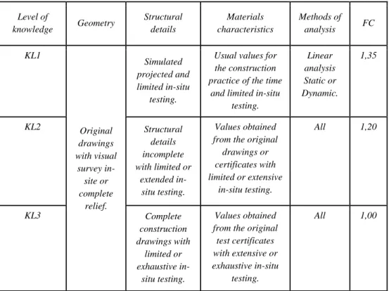
Level of knowledge Geometry Structural details Materials characteristics Methods of analysis FC KL1 Original drawings with visual survey in-site or complete relief. Simulated projected and limited in-situ testing.
Usual values for the construction practice of the time
and limited in-situ testing. Linear analysis Static or Dynamic. 1,35 KL2 Structural details incomplete with limited or extended in-situ testing. Values obtained from the original drawings or certificates with limited or extensive in-situ testing. All 1,20 KL3 Complete construction drawings with limited or exhaustive in-situ testing. Values obtained from the original test certificates with extensive or exhaustive in-situ
testing.
All 1,00
Table 1.1: Levels of knowledge depending on the information available and consequent methods of analysis allowed.
If you wish to reach a Limited Knowledge level (KL1), the three main parameters mentioned above, should be managed as follow7:
- Geometry: geometry of the structure is known according to a in-situ relief or from the original drawings. In the latter case, a visual survey must be carried out to verify the correct correspondence
14 Chapter 1. Italian Standards and guidelines between drawings and building (i.e. number of structural elements, main dimensions of columns and beams, span dimensions etc..). The data collected on the size of the structural elements will be sufficient to enable the development of a model suitable for a linear analysis. - Structural details: details are not available from the constructional
drawings and must be determined on the basis of a simulated project carried out according to the practice of the period of construction. Limited in-situ tests are required for the reinforcement rods and for the most important connection elements. The data collected will be sufficient to enable verification of local strength or the development of a model suitable for a linear analysis.
- Material characteristics: if no information is available on the mechanical characteristics of the materials employed, neither by the constructional drawings nor by the test certified, it has to be taken into account of the usual values for the construction practice of the time validated by limited in-situ tests on the most important elements.
If you wish to reach a Normal Knowledge level (KL2), the three main parameters mentioned above, should be managed as follow:
- Geometry: geometry of the structure is known according to a in-situ relief or from the original drawings. In the latter case, a visual survey must be carried out to verify the correct correspondence between drawings and building. The data collected on the size of the structural elements, together with those concerning the structural details, will be sufficient to enable the development of a model suitable for a linear and non-linear analysis.
- Structural details: details are known from an extensive in-situ testing program or partially available from the incomplete original construction drawings. In the latter case, a limited in-situ survey is
Chapter 1. Italian Standards and guidelines 15 required to verify the reinforcement rods and the most important connection elements. The data collected will be sufficient to enable verification of local strength or the development of a model suitable for a non-linear analysis.
- Material characteristics: information concerning mechanical characteristics of materials are available, based on construction drawings, original test certificates or extensive in-situ testing program. In the first case it has to be carried out also limited in-situ testing program. If the data obtained from the in-situ tests are smaller than those available from the construction drawings or by the original certificates, it has to be carried out extensive in-situ testing program. The data collected will be sufficient to enable verification of local strength or the development of a model suitable for a non-linear analysis.
If you wish to reach a Full Knowledge level (KL3), the three main parameters mentioned above, should be managed as follow:
- Geometry: geometry of the structure is known according to a in-situ relief or from the original drawings. In the latter case, a visual survey must be carried out to verify the correct correspondence between drawings and building. The data collected on the size of the structural elements, together with those concerning the structural details, will be sufficient to enable the development of a model suitable for a linear and non-linear analysis.
- Structural details: details are known from an exhaustive in-situ testing program or available from the original construction drawings. In the latter case, a limited in-situ survey is required to verify the reinforcement rods and the most important connection elements. The data collected will be sufficient to enable verification of local
16 Chapter 1. Italian Standards and guidelines strength or the development of a model suitable for a non-linear analysis.
- Material characteristics: information concerning mechanical characteristics of materials are available, based on construction drawings, original test certificates or exhaustive in-situ testing program. In the first case it has to be carried out also extensive in-situ testing program. If the data obtained from the in-in-situ tests are smaller than those available from the construction drawings or by the original certificates, it has to be carried out exhaustive in-situ testing program. The data collected will be sufficient to enable verification of local strength or the development of a model suitable for a non-linear analysis.
1.4.2 Geometry (carpentry)
The geometry of the building investigated (i.e. determination of the geometric characteristics of its structural elements) must be determined by analyzing the following project documents:
- Original carpentry drawings: they show the geometry of the structure, the structural elements and their dimensions. They also allow to identify the structural frame that resists to the horizontal and vertical actions.
- Construction or executive drawings: they describe the geometry of the structure, the structural elements and their dimensions. They also allow to identify the structural frame that resists to the horizontal and vertical actions. In addition, they hold information about the amount, the placement and the construction details of all the reinforcement rods, as well as the nominal mechanical characteristics of the materials used.
Chapter 1. Italian Standards and guidelines 17 - Visual survey: it is used to verify the effective correspondence
between the actual geometry the available original carpentry drawings. It includes the sample survey of the geometric characteristics of some elements. In the case of undocumented modifies that occurred during or after the construction period, it will carried out a complete relief as described in the following section. - Complete relief: it is used to produce a complete documentation
(carpentry drawings) if the original ones are missing or if is found any incongruity between carpentry drawings and actual geometry of the structure. The material produced has to describe the geometry of the structure, the structural elements and their dimensions. It also allows to identify the structural frame that resists to the horizontal and vertical actions with the same degree of detail of the original drawings.
To correctly identify the geometry of the structure, the obtained data must include the following parameters:
- Identification of the structural frame that opposed to the horizontal
actions in both directions;
- Framework of the floors;
- Geometrical dimensions of beams, columns and walls;
- Possible eccentricity between columns and beams in their
18 Chapter 1. Italian Standards and guidelines
1.4.3 Construction details
The construction details of the building investigated must be determined through the following phases:
- Simulated project: it is used in absence of the original construction drawings to define the amount and the placement of the reinforcement rods in all the structural elements. It is also employed to determine the most important characteristics of the principal connections. It is performed according to technical standards and the construction practice in use at the building time.
- Limited in-situ tests: They are used to verify the correspondence between the reinforcement rods or the characteristics of the principal connections actually present in the building and those reported in the constructional drawings, or obtained by the simulated project.
- Extensive in-situ tests: They are used as an alternative to the simulated project (in accordance to limited in-situ tests) when the original construction drawings are not available or incomplete.
- Exhaustive in-situ tests: They are used to reach a full knowledge level (KL3) when the original construction drawings are not available.
The in-situ testing programs are carried out on an appropriate amount of structural elements for each different type (beams, columns, walls, etc..) as shown in the table 1.2.
To correctly identify the construction details, the obtained data must include the following parameters:
- Amount of longitudinal reinforcement rods in beams, columns and
walls;
- Number of elements and structural detail of transverse
Chapter 1. Italian Standards and guidelines 19
- Amount of longitudinal reinforcement rods in the floors that
contributes to the negative moment in T-beams;
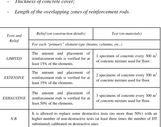
- Support lengths and constraint conditions of the horizontal elements; - Thickness of concrete cover;
- Length of the overlapping zones of reinforcement rods.
Tests and Relief
Relief (on construction details) Test (on materials)
For each “primary” element type (beams, columns, etc..)
LIMITED
The amount and placement of reinforcement rods is verified for at least 15% of the elements.
1 specimen of concrete every 300 m2 of concrete mixture used for floor.
EXTENSIVE
The amount and placement of reinforcement rods is verified for at least 35% of the elements.
2 specimens of concrete every 300 m2 of concrete mixture used for floor.
EXHAUSTIVE
The amount and placement of reinforcement rods is verified for at least 50% of the elements.
3 specimens of concrete every 300 m2 of concrete mixture used for floor.
N.B.
It is allowed to replace some destructive tests (no more than 50%) with an higher number of non-destructive tests (at least three times the number of DT substituted) calibrated on destructive ones.
Table 1.2: Definition of the different levels of relief and testing programs for reinforced concrete structures.
20 Chapter 1. Italian Standards and guidelines
1.4.4 Material characteristics
The mechanical characteristics of the materials used in the building investigated must be determined through the following phases (the appropriate testing program for different cases is shown in Table 1.2):
- Concrete: the evaluation of the mechanical characteristics is obtained coring samples subsequently tested in compression up to failure.
- Steel: the evaluation of the mechanical characteristics is obtained taking a set of reinforcement rod samples subsequently subjected to tensile tests up to failure. The data obtained must allow the determination of the yield strength and the ultimate strain strength (with the exception of the case in which those values are available by test certificates consistent with those required for a new constructions).
- Connections of steel elements: the evaluation of the mechanical characteristics is obtained taking a set of samples subsequently subjected to tensile tests up to failure. The data obtained must allow the determination of the yield strength and the ultimate strain strength.
- Non-destructive test methods: NDT methods are allowed only for attested reliability. They cannot be used on their own or as a replacement of the above mentioned. They can also be used to integrate the destructive tests (DT), provided the NDT results are calibrated to those obtained with DT methods. For the concrete, it is important to use testing methods able to limit the influence of carbonation phenomena on the evaluation of the compressive strength of concrete.
- Limited in-situ tests: they allow to integrate the information on material properties obtained by the standards in force at the time of the construction, or by the nominal characteristics reported on construction drawings, or by the original test certificates.
Chapter 1. Italian Standards and guidelines 21 - Extensive in-situ tests: they allow to obtain information on material properties in absence of both construction drawings and original test certificates. They are also used when the data obtained from limited in-situ tests are lower than those reported in construction drawings or original test certificates.
- Exhaustive in-situ tests: they allow to obtain information on material properties in absence of both construction drawings and original test certificates. They are also used when in required a level of Full Knowledge (KL3) and the data obtained from limited in-situ tests are lower than those reported in the construction drawings or original test certificates.
1.4.5 Factors of confidence (FC)
The factors of confidence (FC) are determined to define the material strengths to be used in further verifications or in the analytical models in absence of more exhaustive evaluations. The mean strengths obtained by both in-situ tests and additional information are divided for the factors of confidence. They can also be different for each type of materials (on the basis of statistical considerations conducted on a set of meaningful data for the considered elements).
1.5
NDT methods in Italian standards for construction
The Non-Destructive Testing (NDT) are the complex of in-situ examinations, testing and inspections, carried out on the whole building or parts of it, that do not damage the material or cause any local damage usually accepted. The results obtained from these test type represent the basis to evaluate the quality of a particular material, to examine the integrity or to diagnose and research the causes of deterioration. The development of these NDT methods in construction is due to two main factors: firstly, the increased interest in condition monitoring of existing buildings, and
22 Chapter 1. Italian Standards and guidelines secondly the increased focus of the recent technical standards on the characteristic of "durability" to ensure the buildings. These test type were initially designed for testing machinery, engines and heir components. Then, given the results achieved and the technological development in this field, the Italian standard has begun to employ NDT as an useful tool to evaluate the seismic vulnerability of buildings8. Only in recent years, they are acquiring their own fundamental importance. The main problem with regard to NDT has always been about the reliability of the results and their evaluation. These two factors represent the basis of structural integrity assessment of a component and/or materials, and, consequently, help to establish the level of quality of each product.
In this context we need a technical standards able to unifying both results and methods employed. This role is played by the international unification institute, such as UNI (Italian organization for Unification), ISO (International Organization for Standardization) and CEN (Comité
Européen de Normalisation). The role of this unification institute mainly
concerned with the regulation of aspects of calibration, execution and interpretation of results obtained through these tests.
The evolution of Italian standards that deals with NDT methods regards mainly the last twenty years, and can be summarized as follows:
Ministerial Decree 09/01/96
‐ Section 3.1: ("Static testing - General requirements"): part of the activities and obligations imposed on the tester, in addition to those considered "mandatory", is left to the "discretion” of the tester “to
conduct these investigations that help to form the belief of the security work" among them, even the "non-destructive testing on structures"; OPCM n.3274/2003
‐ Point 11.2.3.3 ("Levels of knowledge"): in order to adequately support the safety assessment of existing buildings, is provided the use of
"in-
8
Chapter 1. Italian Standards and guidelines 23
situ tests" and "non-destructive test methods” provided that are of
“documented reliability ." It states that "the same cannot be used in
complete replacement of the above" (i.e. compression tests), "but only recommended to their integration, provided the results are calibrated to those obtained with destructive tests."
Ministerial Decree 14/09/05
‐ Point 8: ("Static testing - General requirements"): replace quite similar the previous indications presented in Section 3.1 of the D.M. 09/01/96. The main difference between this two Ministerial Decrees mainly concerned the purpose with the introduction of the concept of "durability" of the building (this purpose wasn’t indicated in the previous ones).
‐ Point 11.1.6 ("Verification of the actual concrete strength") the use of NDT is provided in cases where other tests do not give satisfactory results or when "arise doubts about the quality and responsiveness of
the concrete values of resistance” or when it “becomes necessary to evaluate retrospectively the actual properties of concrete". Also in this
case, it is specified that "these tests must not, in any case, intended to
substitute the acceptance tests."
Similar elements to the previous standard can also be found both in the actual Italian technical standards for construction (NTC 2008) and in the
Chapter 2. Non-destructive testing for the evaluation of concrete 25
Chapter 2
Non-destructive testing for the evaluation
of concrete
Sommario
Su un campione di edifici scolastici realizzati tutti tra gli anni 60 e 70 è stata condotta una campagna di prove sperimentali costituita da prove distruttive e non distruttive preliminare alla valutazione della vulnerabilità sismica. In prima istanza sono state effettuate accurate indagini pacometriche volte alla determinazione delle aree di calcestruzzo non interessate dalle prove di caratterizzazione meccanica. L’indagine pacometrica è la metodologia non distruttiva per la localizzazione delle armature negli elementi in calcestruzzo armato. Questo metodo si avvale del principio della misurazione dell'assorbimento del campo magnetico, prodotto dalla stessa apparecchiatura, che viene evidenziato tramite sistema analogico o digitale. Successivamente si è provveduto ad eseguire prove di tipo non distruttivo per la valutazione della resistenza caratteristica a compressione con il metodo combinato SonReb che deriva dall’utilizzo di due strumenti: lo Sclerometro e il Rilevatore Ultrasonoro. L’indagine sclerometrica consente di determinare la durezza superficiale del calcestruzzo mediante la misura del rimbalzo di un'asta proiettata sulla superficie della struttura stessa. Attraverso curve di correlazione si può inoltre stimare la resistenza a compressione del calcestruzzo. L’indagine ultrasonica invece consente la valutazione
26 Chapter 2. Non-destructive testing for the evaluation of concrete dell’uniformità di calcestruzzo delineando al contempo le zone di degrado o di scarsa qualità. Questa metodologia di prova non distruttiva viene anch’essa impiegata per stimare la resistenza a compressione del calcestruzzo mediante opportuna correlazione del valore di velocità di propagazione degli ultrasuoni nel materiale. La valutazione della resistenza a compressione del calcestruzzo è solitamente basata sulle relazioni empiriche tra risultati ottenuti mediante prove distruttive e parametri ottenuti attraverso l’impiego dei test non distruttivi precedentemente citati. Per la valutazione non distruttiva della resistenza del calcestruzzo esistono numerose formulazioni in letteratura corrispondenti alle curve di isoresistenza, dalle quali dati i valori di velocità media di propagazione dell’onda ultrasonora e l’indice medio di rimbalzo si ottiene il valore di resistenza del calcestruzzo: il candidato si è concentrato sull’applicazione delle formule di R. Giacchetti, L. Lacquaniti (1980); J.
Gasparik (1992) e A. Di Leo, G. Pascale (1994) come consigliato dalle
Indicazioni Tecniche della Regione Toscana.
2.1
Introduction
The increasing technological development in the construction field offers, nowadays, the possibility of analyze buildings with non-invasive experimental techniques able to provide as much information as possible. The conceptual basis of these techniques is certainly found in the “experimental
method1”. The benchmark of this method is the determinism that is the
concatenation required between a phenomenon and the causes that produce it and must be divided into three main phases:
1 The experimental method is the scientific method introduced by F. Bacon and G. Galileo in
the seventeenth century. This method is based mainly on observation of physical phenomena, the use of mathematics and the reproducibility of the experiment. Through the observation of phenomena and the testing repeated the scientist can interpret and determine the mathematical relationships underlying natural phenomena. The scientist formulates scientific hypotheses and subject them to the control of the experimental method. The confirmed hypothesis by repeated experiments turn into scientific laws.
Chapter 2. Non-destructive testing for the evaluation of concrete 27 - Testing program (i.e. the definition of what we need to test);
- Execution of tests;
- Analysis of results (i.e. the verification of the expected forecasts in relation with any differences between forecasts and results obtained).
Thus the use of NDT methods leads to the estimation of the mechanical characteristics of the material from the measurement of a non-destructive parameters appropriately correlated, as generally between them there is no direct physical correlation. Therefore, as an indirect methods, it is important to calibrate the results on an adequate number of destructive tests. In addition from a careful analysis of the literature it can be seen as often these parameters are influenced by specific factors linked to the state of conservation of materials (i.e. in concrete structures the phenomenon of carbonation alters the values of surface hardness). Thereof it can be easily deduced that in order to obtain a reliable result is not sufficient to use only one technique, but it is advisable to integrate multiple techniques able to complement each other.
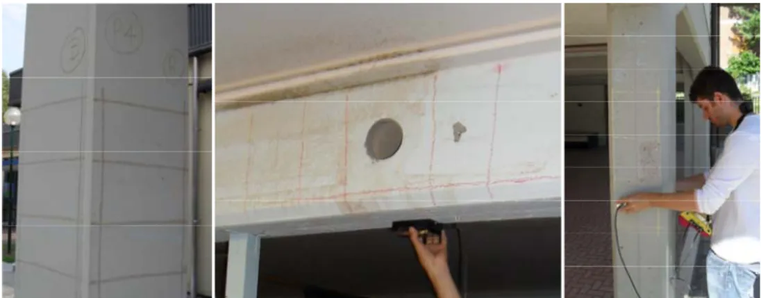
Thus the candidate has led a campaign of experimental tests composed of non-destructive and destructive tests prior to the evaluation of seismic vulnerability on a series of reinforced concrete school buildings built between the 60s and 70s. Firstly it has been carried out a detailed covermeter investigations due to determine the areas of concrete not affected by the mechanical characterization tests. The covermeter survey is a non-destructive methodology employed to localize the steel reinforcement in concrete elements. This method consists of applying an magnetic field to the element under inspection and measuring the absorption of this field by means of the use of a scanning magnetic field sensor.
Then the candidate proceeded to perform non-destructive tests to evaluate the characteristic concrete compressive strength with the combined method SonReb resulting from the use of Rebound hammer and the Ultrasonic Pulse
28 Chapter 2. Non-destructive testing for the evaluation of concrete surface hardness of concrete by measuring the rebound of a metal rod projected on the surface of the investigated material. Through correlation curves it can be also estimated the compressive strength of the concrete since the mean value of Rebound Index (RI).
Instead UPV test allows the evaluation of the uniformity of concrete outlining at the same time decayed areas or surface of poor quality. Also this NDT method is used by itself to estimate the compressive strength of concrete by means of appropriate correlation of the value of ultrasound propagation velocity in the material. In literature there are many formulations able to ensure this correlation: among the available the candidate has chosen the formulas proposed by Hisham, Y. Qasrawi (2000); R. Giannini (2003) and M.
Bilgehan, P. Turgut (2010).
The evaluation of the concrete compressive strength by means of the combined method SonReb is usually based on empirical relationships between the results obtained with destructive tests (i.e. samples taken from the structure and subjected to compression tests) and parameters obtained through the use of NDT methods previously cited (i.e. RI and UPV). There are many formulations in literature corresponding to the correlation curves, to which it is possible to evaluate the value of concrete strength since average data of UPV and RI: the candidate has focused his attention on the application of formulas of R. Giacchetti, L. Lacquaniti (1980); J. Gasparik (1992) and A.
Di Leo, G. Pascale (1994) as recommended by the Technical Guidelines of
Chapter 2. Non-destructive testing for the evaluation of concrete 29
2.2
Covermeter survey
2.2.1 Generality
Safety structural evaluation of reinforced concrete buildings includes both the estimation of in-situ mechanical characteristics of concrete and the relief of steel reinforcement (i.e. longitudinal bars and stirrups) in structural elements (i.e. beams, columns, slabs, retaining walls, etc...). In the diagnosis of existing buildings, if the position and dimensions of the concrete elements are easily measurable, it cannot be said the same as regards both the arrangement and the diameter of the reinforcing bars contained in the elements themselves. It is a fundamental task to recovery a large number of information about the steel reinforcements in a concrete structure in order to verify its actual condition. In fact it is well known that an adequate cover to the steel reinforcement is necessary to ensure that the steel is maintained at a sufficient depth into the concrete, away from the effects of carbonation or aggressive chemicals. On the other hand, an excessively deep cover can favors both the increasing of crack widths and the decreasing of lever arm.
For the non-destructive determination of this information, it should be adopted an appropriate techniques such as, for example, the
covermeter2 survey. The presence of
reinforcement elements in concrete can be detected by the influence that reinforcing steel has upon a magnetic field induced by the covermeter. The covermeter operates by measurement of the reluctance of the magnetic circuit.
2 In 1951 the “covermeter” was developed in England by the Cement and Concrete
Association in conjunction with the Cast Stone and Cast Concrete Products Industry.
30 Chapter 2. Non-destructive testing for the evaluation of concrete
2.2.2 Normative references
The following referenced documents are indispensable for the correct application of this type of investigation. The first to provide a detailed standard on how to carry out a correct covermeter survey were the British Standards (BS) in 1988, later integrated into European standards (UNI EN). Since the first versions of the standards emphasizes the importance of preventive calibration phase3 of the instrument in order to optimize the results of the survey itself. The most important Italian, European and International standards that governing the test execution, instrument calibration and interpretation of results are:
- BS 1881-204:1988 Testing concrete. Recommendations on the use of electromagnetic cover meters;
- ACI 228.2R: 1998 (Revisited 2004) Nondestructive Test Methods for Evaluation of Concrete in Structures
- DIN 1045:3-2008 Concrete, reinforced and prestressed concrete structures - Part 3: Execution of structures;
- UNI EN ISO 15548-1:2009 Non destructive testing – Equipment for eddy current examination – Part. 1: Instrument characteristics and verification;
- UNI EN 13860-2:2003 Non destructive testing – Eddy current examination – Equipment characteristics and verification – Probe characteristics and verification;
- UNI EN 13860-3:2004 Non destructive testing – Eddy current examination – Equipment characteristics and verification – System characteristics and verification;
- UNI EN 1992-1-1:2005 Eurocode 2.
3 British Standard suggests a basic calibration procedure involving a cube of concrete of
Chapter 2. Non-destructive testing for the evaluation of concrete 31
2.2.3 Scope
This test helps to identify steel reinforcement within the structure and is used to determine steel reinforcement bar spacing, size of reinforcement bars and the depth of reinforcement from surface without damaging the structure under examination. Finding information on the reinforcement rods is an important task also for the execution of quality control and assessment of the mechanical characteristics of concrete using destructive and/or non-destructive test methods. In fact, in this kind of analysis is essential to work in areas where there are no reinforcing bars in order not to influence the results of the investigations themselves. Then, in order to perform properly a non-destructive and/or destructive test methods on reinforced concrete structures, firstly it must be determined the areas where there are steel rods so as to exclude them to:
a) carry out the Rebound Hammer tests (i.e. to avoid any alterations of the rebound index value);
b) carry out UPV tests (i.e. to avoid any alterations of the propagation velocity as a result of the presence of material with different transmission properties compared to concrete);
c) carry out drilling core samples (i.e. to avoid any alterations in subsequent compression tests).
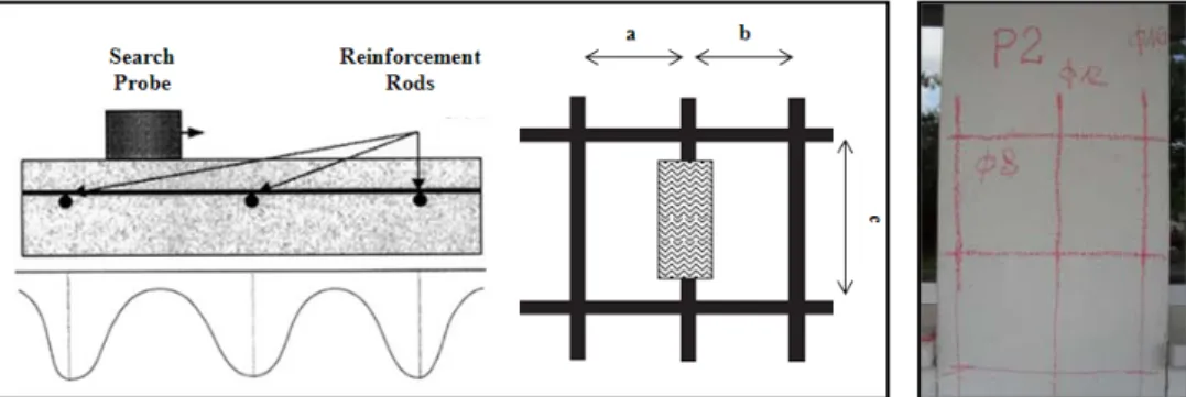
Fig. 2.2. Different aims for a covermeter survey: a) to estimate the actual arrangement, number and diameter of reinforcing bars; b) to identify concrete areas on which drilling core samples; c) to identify concrete areas on which carrying out NDT methods.
32 Chapter 2. Non-destructive testing for the evaluation of concrete
2.2.4 Test equipment and applications
The covermeter, also called
pachometer (Fig. 2.3), is a portable
reinforcement bars locaters instrument that can be easily used on-site. It is composed by a control unit able to emit/read the electromagnetic field and an emitter/receiver magnetic field probe (characterized by a layer of paramagnetic material). Its use allows a reliable reconstruction of reinforcement, together with the concrete cover to the bar and/or the size of the bar.
The position and direction of steel reinforcement can be determined by moving the search probe of over the surface of the investigated element until the control unit shows a maximum deflection. At this position the reinforcing bar is below and parallel to the length of the search head. It is very important to remember that the probes are highly directional. This means that all probes have both a long and a short axis. A distinct maximum in induced current is observed only when the long axis of the probe and the reinforcement are aligned and when
Fig. 2.3. A covermeter survey equipment used to locate reinforcement.
Fig. 2.4. A covermeter survey on the surface to be investigated.
Chapter 2. Non-destructive testing for the evaluation of concrete 33 the probe is directly above the reinforcement. Marking with chalk the position of the reinforcing bars as determined by the instrument it is possible to establish also the spacing of reinforcing bars embedded in concrete. It can be also used to search other metal objects embedded inside the structure (i.e. pipes, electrical wires, rods, etc...) or – in a more general way – for the location of curbs, lintels, columns and slabs of ribs that are not directly visible. The traditional type of covermeter is based on the principle of
magnetic induction that is, on the perturbation of a magnetic field generated
by a probe that is made to slide in a continuous way on the surface to be investigated (Fig. 2.4). The search probe is able to work with the perturbation because it is made up with materials that have a different and higher magnetic permeability than that of the concrete in which are inserted the steel reinforcements. The probe that slides on the investigated surface is a coil traversed by an alternating current of constant frequency which generates an alternating magnetic field (Foucault induced currents or eddy currents). The presence of metal objects in the area of influence of the magnetic field alter the potential difference of the coil in accordance with the principle of magnetic induction. The alteration of the voltage – showed by means of a instrument's graduated scale (located in the control unit) – is strongly influenced both by the thickness of the metallic object and the concrete cover. As depth/spacing ratios increase, it becomes more difficult to discern individual bars.
Fig. 2.5. Alteration of the signal due to the slide of the probe on the structural elements: scheme and output of the survey.
34 Fo str us re th ca th el te 4 or this reas rongly arm se of coverm epresents the he distance o an be determ his methods lements: in emperatures Position Point P2 Column Ground Floo Chapter son, in the med structure meter. The e peaks ass of each peak mined from s concern n fact such below free or – plaster – vertica – horizo – mean c r 2. Non-des case of hig es (i.e. pres sinusoidal ociated with k to the edg an opportun the operat h instrume zing. rwork (thickne al reinforceme ontal reinforce concrete cove S Note. All m structive testi gh concrete stressed stru shape of th h any reinfo ge of the cha nity calibrat ting temper nts will n Descri ess 1,5 cm); ent rods Ø 16 ement rods Ø 8 er 3,5 cm. Scheme measures are in
ing for the ev e cover or
uctures) bec he recorded orcing bars art paper gra tion curve. S rature rang not function iption mm and Ø 12 8 mm, steps o [cm] valuation of in the pres comes diffi data (see F and, by me aph, depth o Some drawb ge of inve n satisfacto 2 mm; f 20 cm; concrete sence of icult the Fig. 2.5) easuring of cover backs of estigated orily at
Chapter 2. Non-destructive testing for the evaluation of concrete 35
2.3
Rebound Hammer test
2.3.1 Generality
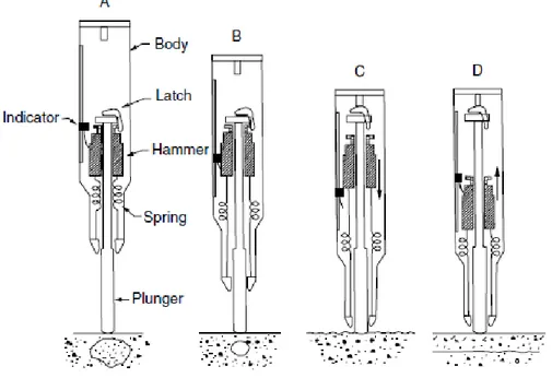
The Rebound hammer is a hand held instrument used for testing the quality of hardened concrete in an existing structures. The test device was developed in 1948 by Ernst Schmidt4 at the Swiss Federal Materials Testing and Experimental Institute in Zurich. The instrument is based upon the rebound
principle. The latter one says that the rebound of an elastic mass impacting on
a surface is a function of the hardness of the surface itself. Hence the harder the surface, the higher is the rebound value obtained. The development of this new device draws its inspiration from tests carried out to measure hardness of metals.For this reason, this instrument can be considered as an outgrowth of the Scleroscope5 test, which measures the superficial hardness of a material considering the rebound height of a diamond-tipped hammer, or mass, that is dropped from a fixed height above the test surface.
Due to its simplicity and low cost, the rebound hammer represents the most widely NDT methods used for concrete evaluation. While the test appears simple, there is no direct relationship between the rebound number and the strength of concrete. Since 1958, many authors6 has attempted to establish a correlation between the Rebound Index (RI) and the concrete surface hardness as measured by the Brinell method with poor results.
4 E. Schmidt, Der Beton, Prufhammer. Schweiz, Bauz. (Zurich), 1958, p. 378 5 In Greek, the word “sklhros” means “hard”.
6 J. Kolek, An appreciation of the Schmidt rebound hammer, Mag. Concr. Res. (London),
10(28), 27, 1958.
36 Chapter 2. Non-destructive testing for the evaluation of concrete
2.3.2 Normative references
Due to the high degree of uncertainty associated with strength predictions based upon the rebound hammer test, it took many years before the development of the test method and its first certified standards. The first one was issued by British Standards Institution in 1971, followed by the American Society for Testing and Materials in 1975 (ASTM C 805 75-T), and by the International Union of Laboratory and Experts in Construction Materials, System and Structures (RILEM) in 1977. Nowadays many international institute of standardization has adopted standards for the test execution, instrument calibration and interpretation of results, even if this test methods is not recommended by itself. The most important are:
- BSI BS 1881-202:1986 Methods of Testing concrete. Part 202: Recommendations for Surface Hardness Testing by Rebound Hammer;
- ASTM C805/C805M-08 Standard Test Method for Rebound Number of Hardened;
- DIN 1048-2:1991 Testing concrete; testing of hardened concrete (specimens taken in situ);
- UNI EN 12504-2:2001 Testing concrete in structures – Part. 2: Non destructive testing – Determination of rebound number;
- ACI Committee 228: 2003 In-place methods for determination of strength of concrete, Technical Committee Doc. 228.1R-03, American Concrete Institute;
- UNI EN 1992-1-1:2005 Eurocode 2;
- UNI EN 13791: 2007 Assessment of in-situ compressive strength in structures and precast concrete.
Chapter 2.3.3 S This te reboun elemen distanc surface is some hardnes the reb estimat compre correlat compre and/or hardnes finishin layer, c influen Usually strength method order o non-ho of mate Thus, besides reboun be used assess areas c poor qu r 2. Non-des Scope est type is d surface h nt by mea ce of a m e of the elem e correlatio ss and mec bound ham te the v essive stre tion betwee ession stren indirectly o ss of the ng and com curing the nce the y, for determ h with the d, an estim of 15 ÷ 20% omogeneous erial. because o s concrete s d number, t d only for qu the unifor characterize uality or det structive test used to de hardness of asuring th mass project ment itself. on between chanical stre mmer is use values of ength. In en surface h ngth depen on many fac aggregate mpaction of surface, etc effectivene mining the c application mated accur % is achieved s and isotrop of the ma strength than this NDT m uick survey rmity of co ed by the p teriorated co
ing for the ev
etermine the f a concrete he rebound ted on the Since there the surface ength, often ed alone to f concrete fact, the hardness and nds directly tors (i.e. the e elements the cortica c..) that can ess itself compressive n of this tes racy in the d, due to the pic behavior any factors n can affec methods can ys in order to oncrete and presence o oncrete. valuation of e e d e e e n o e e d y e s, al n f. e t e e r s t n o d f Rebound Hammer Rebound Hammer Fig. 2.7. with rebo uniformity floors in t Fig. 2.8. S f concrete Typical surv ound hammer y of concrete the same elem
Surface prepa First Floor Ground Floor vey carried o r to assess t along differe ent. aration. 37 d out the ent