Thermal-hydraulic study and optimization
of the DEMO Water Cooled Lithium-Lead
Breeding Blanket
Facoltà di Ingegneria Civile e Industriale
Dottorato di Ricerca in Energia e Ambiente - Scuola di Dottorato in Scienze e Tecnologie per l’Innovazione Industriale – XXXIII Ciclo
Candidate
Francesco Edemetti ID number: 1343253
Thesis Advisor
Prof. Gianfranco Caruso
ABSTRACT
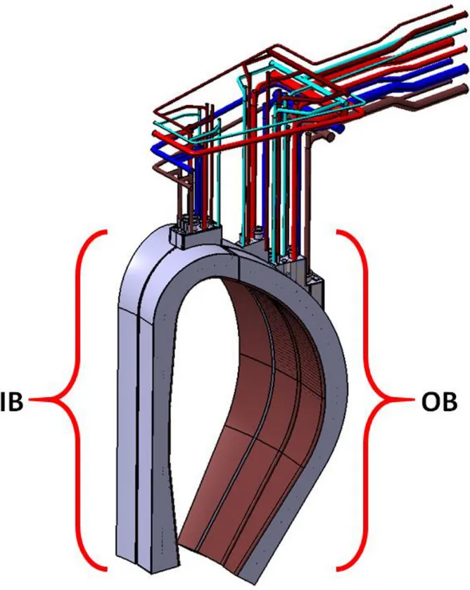
One of the key components of a nuclear fusion power plant is the Breeding Blanket (BB), in charge of ensuring the essential functions of Tritium production, shield the Vacuum Vessel (VV) and remove the heat generated in the toroidal chamber. Two conceptual designs are currently being studied for the implementation in the DEMOnstration Fusion Reactor (DEMO) in the framework of R&D activities under the coordination of the EUROfusion Consortium. One of these two BB is the Water-Cooled Lithium-Lead (WCLL), which relies on two different fluid: the water, necessary to remove the generated heat in the tokamak and to shield the vacuum vessel from neutrons, and the Lithium-Lead (PbLi) eutectic alloy, adopted as breeder and neutron multiplier, necessary for the Tritium production in order to make the fusion self-sustaining. The first function is fulfilled by two independent cooling systems: the First Wall (FW), that facing the plasma removes the heat flux raised from it, and the Breeding Zone (BZ), that removes the deposited power due to neutron and photon interaction inside the breeder. To guarantee good energy conversion efficiencies, these two systems must operate under certain conditions, and pressurized water at the typical pressure of the nuclear Pressurized Water Reactor (PWR) is adopted.
The Ph.D. work has been developed in collaboration with ENEA Brasimone Research Center, under the coordination of the EUROfusion Consortium in the task of the Work Package Breeding Blanket.
The aim of this Ph.D. thesis is to contribute to the development of the conceptual design of the WCLL breeding blanket, in order to design an efficient and reliable system, demonstrating the capability to fully withstands the DEMO requirements in normal and off-normal conditions. The activity has been focused on the thermal-hydraulic of the system; specifically, the analyses were performed on one single elementary cell, that compose the WCLL due to its periodicity. To perform realistic analyses, multiple factors have taken into account: engineering aspects, neutronic and thermo-mechanic. This has been pursued through the engineering approach and with the application of the numerical CFD code to represent the behaviors of the different analyzed models.
The first part of this study (Chapter 3) starts from the WCLL design review, which is described in Section 3.1. This section concerns the previously studied and developed configurations of
Subsequently, in Chapter 4, different thermal-hydraulic analyses have been performed through numerical simulations, where a complete three-dimensional finite volume model of the WCLL elementary cell has been set-up in each analysis, using the commercial CFD code ANSYS CFX v18.2. Several steady-state analyses have been performed in order to optimize the BZ tubes layout, the FW cooling system, the BZ manifold layout and to evaluate the impact of the heat transfer modelling approach through the PbLi modelling and its properties. Once the CAD has been defined, the thermal power and the related cooling systems, FW and BZ, have been set through an analytical approach, in order to guarantee compliance with the main DEMO requirements design. The numerical model includes fluid and solid domains, representing in detail the WCLL elementary cell with its different structures and fluids. The Section 4.3 has the aim of optimizing the arrangement of the BZ pipes, guaranteeing a Eurofer temperature below the imposed limit of 550°C, and water at certain conditions in compliance with the thermodynamic cycle assumed for the electricity production. Several configurations have been analyzed to identify a promising BZ coolant system layout, which satisfies the DEMO requirements. The CFD analyses have been carried out investigating the temperature field of the solid structures, Eurofer and Tungsten, and also the thermal-hydraulic performances of the water-cooling systems and PbLi. These optimization analyses led to the V0.6 configuration, which has set the minimum number of BZ tubes to 22 and ensuring a symmetric temperature field in the toroidal direction in the BZ and FW systems and concerning the FW also in poloidal direction, a maximum temperature of the Eurofer structures of around 500°C, which not exceeds the imposed limit of 550°C.
In the next paragraph, the Section 4.4, a FW water channels optimization has been achieved, reducing the channels number from 10 up to 4. This channels reduction has been pursued thanks to the fact that the FW temperature was considerably below the imposed limit of 550°C, and to a DEMO's thermal load review that has led to a modification on the imposed heat flux on the FW from 0.5 MW/m2 to 0.32 MW/m2. The optimization has returned a greater homogeneity of
the temperature field between BZ and FW systems, reducing the passive heat removal of the FW system from the BZ system. Although the pressure drops strongly increase, it has resulted in a decrease in the volume of water present in the first centimeters of the cell which positively affects the Tritium Breeding Ratio (TBR), the fundamental parameter for the Tritium production. The V0.6 configuration with 4 water channels (named V0.6_FW4), fully
withstands the DEMO thermal loads not exceeding the Eurofer temperature limit of 550°C. Another important parameter that has been affected by this reduction is the FW water velocity that has been strongly increased, enhancing the water thermal-hydraulic performances.
In Section 4.5, the results from the analysis of the V0.6_FW4_R model have highlighted that the recirculation manifold have to be adopted to guarantee large and safety margins from a thermal crisis. The recirculation ensures a lower wall temperature in all the BZ tubes, especially in the tubes near the FW which are subjected to greater power deposition. In addition, a greater flow of water flow rate, guarantee a large and safety margin from the possibility of thermal crisis.
The second part of the activity, reported in Section 4.6, concerns the assessment of the assumption made in the numerical model development. Since the PbLi thermal conductivity deeply affects the elementary cell temperature field, due to its huge thermal inertia, a study was also conducted on it. Two different PbLi thermal conductivity have been chosen to evaluate the temperature field of the cell, the suggested Mogahed correlation and the conservative IAEA correlation. The analyses have also been performed with the PbLi domain set as liquid and solid, evaluating the impact of this assumption on the numerical prediction. It has been evaluated that the PbLi modelling approach does not affect the results, increasing the temperature field by only a few degrees in the model with solid PbLi. In addition, simulations with liquid PbLi in forced convection and absence of buoyancy forces and magneto-hydrodynamics effects, have demonstrated that the convective contribution to the heat exchange is actually negligible. The PbLi has, in both cases with forced convection and in the absence of buoyancy effects, a laminar flow. Moreover, to evaluate the liquid metal behavior the Prandtl number has been analytically evaluated. The dimensionless number has shown that the thermal diffusivity, which is related to the rate of heat transfer by conduction, unambiguously dominates prevailing on convection, that can be neglected. Instead, what significantly affects the model is the adopted PbLi thermal conductivity correlation, that with the IAEA causes the Eurofer temperature limit to be exceeded and the hot-spots onset. Due to the choice of setting as reference property, for the PbLi thermal conductivity, the IAEA correlation, the analyses on the updated configuration returns an Eurofer temperature field which exceeds the imposed Eurofer temperature limits in different areas.
The analyses, reported in Section 4.7, have led to a further set of simulations to find out a BZ tubes layout in order to guarantee the respects of the requirements, even in the worst
temperature slightly below the imposed limit of 550°C, extinguishing the structures hot-spots. The V0.6_B has been chosen as final configuration, able to cope with the operative DEMO thermal loads, guaranteeing the respect of the DEMO Eurofer temperature limit and its related requirements.
The last part of this work (Chapter 5) has been focused on the operational phases of the WCLL breeding blanket. One of the main functions of the BB is the conversions of the thermal energy from the fusion reaction in energy suitable for the power generation. The pulsed nature of the DEMO fusion reactor divides the operative phase in two main phases: pulse where the Deuterium and Tritium are burnt and energy is produced for 120 min, and dwell estimated to be 10 min where the central solenoid is recharging, and decay heat is removed. This research activity has been pursued to verify if the selected V0.6_B design is able to face the DEMO operational phases, investigating the response of the systems from the thermal-hydraulic point of view. In Section 5.1, a three-dimensional model has been reproduced according to the main outcomes of the previous Chapter. Different CFD transient analyses have been performed to verify if the selected design is suitable with the DEMO constrains and requirements, investigating different thermal behaviors. Transient thermal-hydraulic analyses have been set-up to simulate the burning phase, composed by ramp-set-up and ramp-down, after which steady state conditions of full power and dwell are reached respectively. Moreover, power fluctuation analyses have been performed to investigate the plasma instabilities caused by the pellets injection during the normal operation, this causes peaks of over or under power. In addition, a further analysis focused on the evaluation of the effect of the PbLi thermal inertia has been performed. This analysis it does not represent any realistic behavior of the reactor, as the previous ones, but it serves to investigate the ideal behavior that would occur in PbLi in case of constant cooling.
Unfortunately, the transient analyses require a significantly higher computational cost, and this implies that in order to obtain results in a reasonable time, it is mandatory to reduce the number of elements in the numerical model. Although it is interesting to obtain extremely accurate output values of the model, the main goal of these analyses is to investigate the global performances of the cooling systems, therefore, in Section 5.2 a mesh sensitivity has been performed in order to reduce the high number of elements without losing accuracy in the obtained results.
To perform the transient analyses different time-dependent thermal loads have been considered. The operational phases of DEMO have been characterized by different power contributions which vary in space and time. These thermal loads have been widely discussed in Section 5.3, identifying the power contribution curves to adopt for the model. In particular, in Section 5.4, the model solver settings and boundary conditions have been set-up per each run.
In Section 5.5, the results have been described and differentiated by steady-state and transient analyses. The first part (Section 5.5.1) concerns the steady-state analyses performed to impose the initial conditions for the transient, and in the second part (Section 5.5.2), the transient analyses have been widely discussed. In particular, in sub-sections 5.5.2.1 and 5.5.2.2, the fast ramp-up and ramp-down phases are respectively analyzed. Both show how the PbLi thermal inertia plays a key role in the rise and fall of the temperature of the structures, ensuring to the systems a slowly gradual trend. The FW system promptly reacts to the power variation, showing a temperature trend similar to the power one. Instead, the BZ system slowly reacts to power variations. It depends on the PbLi thermal inertia, which strongly slows down the temperature trend, causing a considerable delay in reaching steady-state conditions. In both simulations, the Eurofer temperature is below the limit and the operative water constrains are respected and guaranteed.
The study of the power fluctuations has been reported in sub-sections 5.5.2.3 and 5.5.2.4, where the V0.6_B layout has been subjected to different power oscillation. These analyses have been performed for the purpose of studying if the PbLi thermal inertia can mitigate these oscillations, continuing to operate within the required requirements. The thermal-hydraulic goal is that the elementary cell continues to supply water to the Primary Heat Transfer System (PHTS) at the required conditions for the electricity production. In addition, it has been highlighted that, in the remote case of an overpower peaks series, the huge PbLi thermal inertia absorbs these oscillations not provoking a temperature build-up. The same cannot be stated regarding the FW systems where a slight temperature build-up has been evidenced.
In sub-section 5.5.2.5, an unrealistic study has been performed to evaluate the PbLi thermal inertia. The system has been subjected to a step-down ramp, passing from the nominal power to a zero-power condition. The analysis is aimed at identifying the characteristic time trend of both systems. A strong cooling time differentiation, between FW and BZ system, has been highlighted, where the cooling time of the PbLi has different order of magnitude compared with the FW.
the normal operative thermal loads. The second part, instead, has demonstrated that the selected design is able to withstand all the operational phases of the DEMO fusion reactor, confirming the choice made in the first part. The final design has been selected to comply with the DEMO requirements, withstanding the thermal loads, and guaranteeing adequate water conditions for the electricity production during all the reactor phases.
ABSTRACT ... I
LIST OF ABBREVIATIONS ... XIII
LIST OF FIGURES ... XV
LIST OF TABLES ... XX
1.
INTRODUCTION ... 1
1.1.
Framework of the activity ... 3
1.2.
Objectives of the thesis ... 4
1.3.
Thesis structures ... 6
2.
NUCLEAR BACKGROUND ... 8
2.1.
Nuclear fusion technology ... 8
2.1.1. Magnetic confinement ... 9
2.2.
DEMO reactor and components ... 11
2.3.
Fuel cycle ... 14
2.4.
Breeding blanket concepts ... 16
2.4.1. Overview of the previous blanket concepts ... 17
2.4.2. The Helium-Cooled Pebble Bed ... 19
3.
DEMO WCLL BREEDING BLANKET ... 22
3.1.
Previously studied layout ... 25
3.2.
WCLL 2018 configuration ... 33
3.2.1. FW system ... 34
3.2.2. BZ system ... 36
3.2.3. Manifold system ... 37
4.
THERMAL-HYDRAULIC ANALYSES IN STEADY-STATE
CONDITIONS ... 42
4.1.
Material properties ... 44
4.2.
WCLL Thermal loads ... 46
4.3.
BZ system analyses – From WCLL V0.2 to V0.6 ... 48
4.3.1. Numerical models and mesh ... 48
4.3.2. Solver settings and boundary conditions ... 55
4.3.3. Results ... 59
4.3.4. Summary ... 69
4.4.
FW system optimization... 71
4.4.1. Numerical models and mesh ... 71
4.4.2. Solver settings and boundary conditions ... 73
4.4.3. Results ... 76
4.4.3.1. Stand-alone FW optimization ... 78
4.4.3.2. V0.6 layout FW optimization ... 81
4.4.4. Summary ... 87
4.5.
BZ recirculation manifold ... 89
4.5.1. Numerical model and mesh ... 89
4.5.2. Solver settings and boundary conditions ... 91
4.5.3. Results ... 93
4.5.4. Summary ... 99
4.6.
Heat transfer modelling approach ... 101
4.6.1. V0.6 modelling approach comparison ... 101
4.6.1.1. Numerical model ... 101
4.6.1.2. Solver settings and boundary conditions ... 103
4.6.1.3. Mesh independence... 108
4.6.1.4. Results ... 110
4.6.2. V06_FW4_R modelling comparison ... 117
4.6.2.1. Numerical model and mesh ... 117
4.7.3. Results ... 137
4.7.4. Summary ... 149
4.8.
Main achievements ... 152
5.
THERMAL-HYDRAULIC ANALYSES IN TRANSIENT
CONDITIONS ... 154
5.1.
WCLL V0.6_B – Numerical model ... 156
5.2.
Mesh independence analysis ... 159
5.3.
WCLL Transient thermal loads ... 162
5.3.1. Ramp-up and ramp-down ... 163
5.3.2. Power fluctuations ... 169
5.3.3. PbLi thermal inertia ... 170
5.4.
Solver settings and boundary conditions ... 171
5.5.
Results ... 176
5.5.1. Steady-state ... 176 5.5.2. Transient ... 179 5.5.2.1. Fast ramp-up ... 179 5.5.2.2. Ramp-down ... 186 5.5.2.3. Low fluctuations ... 193 5.5.2.4. High fluctuations ... 202 5.5.2.5. Thermal inertia ... 2125.6.
Summary and main achievements ... 216
6.
CONCLUSIONS AND PERSPECTIVES ... 220
ANNEX A: Materials properties ... 225
ANNEX B: Steady-state and transient thermal loads ... 228
LIST OF ABBREVIATIONS
BB Breeder BlanketBC Boundary Condition BoP Balance of Plant
BP Back Plate
BSS Back Supporting Structure
BZ Breeding Zone
CAD Computer Aided Design
CANDU CANadian Deuterium Uranium reactor CB Ceramic Breeder
CEA Commissariat à l'Energie Atomique et aux Energies Alternatives CFD Computational Fluid Dynamics
COB Central Outboard Blanket CP Cooling Plate
CR Research Center CS Central Solenoid
D Deuterium
D-T Deuterium-Tritium (nuclear reaction) DB Dittus-Boelter correlation
DCLL Dual Coolant Lithium Lead (Blanket) DEMO Demonstration fusion power plant
DIAEE Department of Astronautic Electric and Energetic Engineering
DIV Divertor
DWT Double Wall Tube
ECH Electron Cyclotron Heating
EFDA European fusion development agreement
ENEA Italian National Agency for New Technologies, Energy and Sustainable Economic Develpment ESS Energy Storage System
FEM Finite Element Method FPP Fusion Power Plant
FW First Wall
HC Helical
HCLL Helium Cooled Lithium Lead (Blanket) HCPB Helium Cooled Pebble Bed (Blanket)
He Helium
HF Heat Flux
HSP Horizontal Stiffener Plate HTC Heat Transfer Coefficient IB Inboard Blanket
ICH Ion Cyclotron Heating
IHTS Intermediate Heat Transfer System IHX Intermediate Heat Exchanger
ITER International Thermonuclear Experimental Reactor LIB Left Inboard Blanket
LOB Left Outboard Blanket LOCA Loss of Coolant Accident LOFA Loss of Flow Accident MHD Magneto Hydro Dynamic MFR Mass Flow Rate
MMS Multi-Module Segment
PPPT Power Plant Physics & Technology PWR Pressurized Water Reactor
R&D Research and Development
RAFM Reduced Activation Ferritic/Martensitic (Eurofer) RELAP Reactor Loss of Coolant Analysis Program RIB Right Inboard Blanket
ROB Right Outboard Blanket SMS Single-Module Segment
SW Side Wall
T Tritium
TBM Test Blanket Module TBR Tritium Breeding Ratio TES Tritium Extraction System TFC Toroidal Field Coil
TR Tie Rods
TRS Tritium Removal System VSP Vertical Stiffener Plate
VV Vacuum Vessel
WC Water Cooled
WCLL Water Cooled Lithium Lead (blanket)
WP Work Package
WPBB Work Package Breeding Blanket WPBoP Work Package Balance Of Plant
LIST OF FIGURES
Fig. 2.1 – Tokamak magnetic confinement working principles [8] ... 10 Fig. 2.2 – DEMO reactor general layout [12] ... 13 Fig. 2.3 – HCLL breeding blanket design concept (left) and equatorial outboard module (right) [23] ... 17 Fig. 2.4 – DCLL breeding blanket design concept (left) and equatorial outboard module and PbLi flow path (right) [24] ... 18 Fig. 2.5 – HCPB breeding blanket reference design [26][31] ... 21 Fig. 2.6 – HCPB coolant system: schematic flow scheme (left), flow scheme and temperature (right) [26][31]... 21 Fig. 3.1 – WCLL blanket design with IB and OB sector and feeding pipe ... 23 Fig. 3.2 – WCLL blanket concept outboard segment box 1995; manifold section (blue box) and equatorial radial-toroidal view (green box) [40] – (color online version) ... 26 Fig. 3.3 – WCLL blanket concept equatorial outboard module 2012 (CEA), different view [44] ... 27 Fig. 3.4 – WCLL blanket concept equatorial outboard module 2015 (ENEA), different view [39] ... 28 Fig. 3.5 – WCLL blanket concept 2015 (ENEA), PbLi flow path, DWTs and FW channels distributions [39] ... 28 Fig. 3.6 – WCLL blanket concept COB (left) and equatorial elementary cell (right), 2016 (ENEA) [45] ... 29 Fig. 3.7 – WCLL blanket concept 2017 (ENEA) – three different BZ tubes layout [48][49] ... 30 Fig. 3.8 – WCLL blanket concept 2017 half equatorial elementary cell geometry: vertical stiffeners (left) and horizontal stiffeners (right) [55]... 31 Fig. 3.9 – WCLL blanket concept 2017 – different elementary cell configurations and BZ tubes layout (ENEA) [55] ... 32 Fig. 3.10 – WCLL 2018 V0.2 outboard segment internal structures [52] ... 34 Fig. 3.11 – WCLL 2018 V0.2 COB elementary cell isometric view (left), radial division of the areas (right) [53] ... 34 Fig. 3.12 – WCLL 2018 V0.2 FW system: cooling channels scheme (up) and geometrical parameters (down) [53] ... 35 Fig. 3.13 – WCLL 2018 V0.2 BZ system: tubes isometric view (left), cooling scheme (right) [53] ... 37 Fig. 3.14 – WCLL 2018 V0.2 COB elementary cell manifold layout: isometric view (up), radial-toroidal cut (down) ... 39 Fig. 3.15 – WCLL 2018 V0.2 PbLi manifold, inlet and outlet layout holes ... 39
Fig. 4.7 – WCLL 2018 V0.6 layout: PbLi temperature field ... 67
Fig. 4.8 – WCLL 2018 V0.6 layout: PbLi velocity profile ... 67
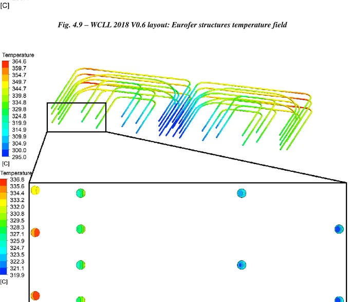
Fig. 4.9 – WCLL 2018 V0.6 layout: Eurofer structures temperature field ... 68
Fig. 4.10 – WCLL 2018 V0.6 layout: DWTs water interface and outlet temperature focus ... 68
Fig. 4.11 – WCLL 2018 V0.6 layout: water channels interface temperature ... 69
Fig. 4.12 – WCLL FW system COB equatorial model with different number of channels [71] ... 72
Fig. 4.13 – WCLL FW 10 stand-alone system: temperature contours ... 80
Fig. 4.14 – WCLL FW 6 stand-alone system: temperature contours ... 80
Fig. 4.15 – WCLL FW 4 stand-alone system: temperature contours ... 81
Fig. 4.16 – WCLL V0.6 FW optimization: FW systems temperature distributions ... 84
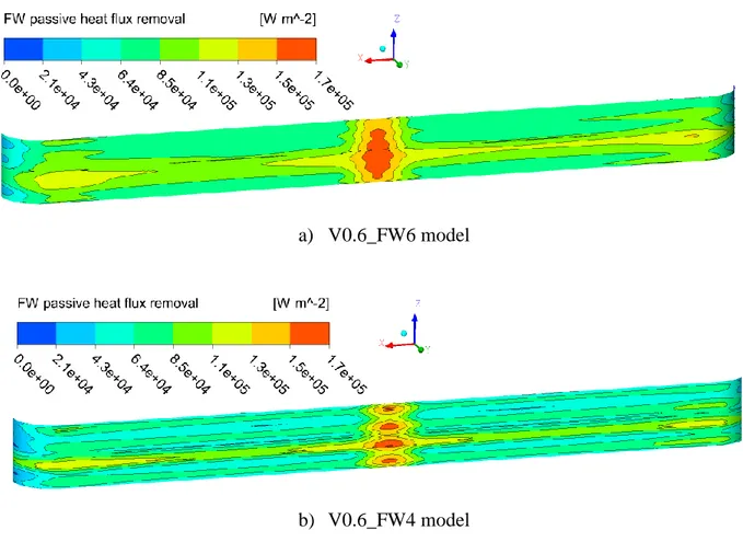
Fig. 4.17 – WCLL V0.6 FW optimization: BZ-FW interface passive heat flux removal ... 85
Fig. 4.18 – WCLL V0.6 FW optimization upper plate temperature distribution ... 86
Fig. 4.19 – WCLL V0.6 FW optimization PbLi radial-poloidal temperature distribution... 87
Fig. 4.20 – WCLL COB equatorial elementary cell manifold rationale [77] ... 89
Fig. 4.21 – WCLL V0.6_FW4_R model and BZ recirculation system ... 90
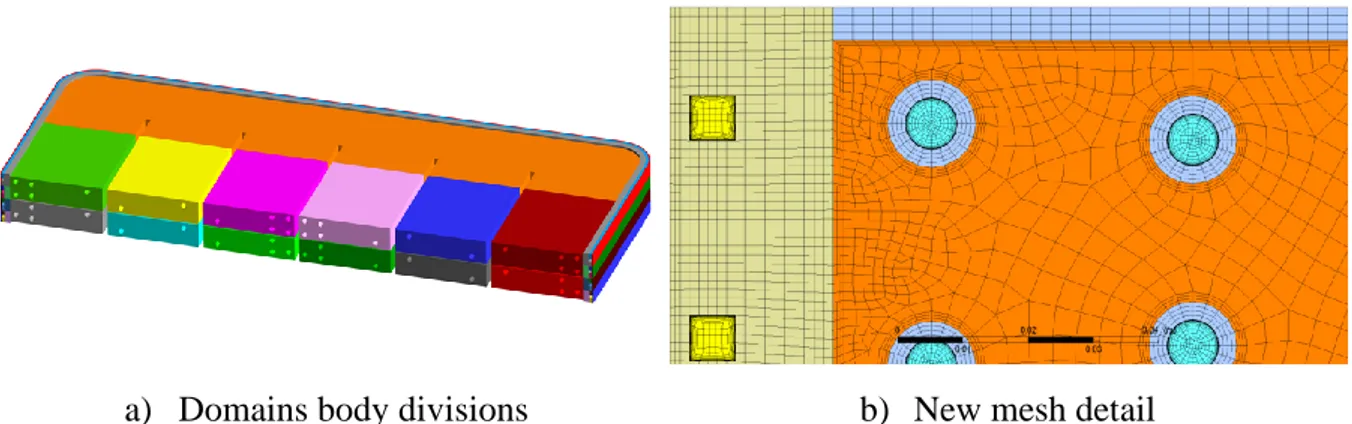
Fig. 4.22 – WCLL V0.6_FW4_R model details: fluids and solids new domain division; new mesh detail ... 91
Fig. 4.23 – WCLL V0.6_FW4_R BZ recirculation manifold: Eurofer structures temperature distribution ... 97
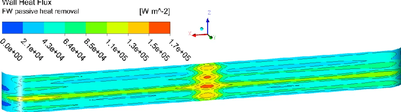
Fig. 4.24 – WCLL V0.6_FW4_R BZ recirculation manifold: BZ-FW interface wall heat flux removal 98 Fig. 4.25 – WCLL V0.6_FW4_R BZ recirculation manifold: PbLi temperature radial poloidal cut .... 98
Fig. 4.26 – WCLL V0.6_FW4_R BZ recirculation manifold: water tubes temperature distribution ... 99
Fig. 4.27 – WCLL 2018 V0.6 layout water coolant schemes ... 102
Fig. 4.28 – Analyses performed divided by thermo-physical properties, approach and models ... 105
Fig. 4.29 – WCLL 2018 V0.6 FEM model mesh sensitivity temperature results ... 110
Fig. 4.30 – FEM analysis upper plate temperature field – IAEA correlation ... 113
Fig. 4.31 – FEM analysis upper plate temperature field – Mogahed correlation ... 113
Fig. 4.32 – FVM purely conductive analysis upper plate temperature field – Mogahed correlation .. 114
Fig. 4.33 – FVM purely conductive analysis upper plate temperature field – IAEA correlation ... 114
Fig. 4.34 – FVM with fluid water and PbLi solid domains upper plate temperature field – Mogahed correlation ... 114
Fig. 4.35 – FVM with fluid water and PbLi solid domains upper plate temperature field – IAEA correlation ... 115
Fig. 4.36 – FVM with fluid water and PbLi domains upper plate temperature field – Mogahed
correlation ... 115
Fig. 4.37 – FVM with fluid water and PbLi domains upper plate temperature field – IAEA correlation ... 115
Fig. 4.38 - WCLL 2018 V0.6 layout heat transfer modelling approach: Eurofer maximum temperature trend ... 116
Fig. 4.39 – WCLL V0.6_FW4_R case #1 Eurofer upper plate temperature distribution ... 123
Fig. 4.40 – WCLL V0.6_FW4_R case #2 Eurofer upper plate temperature distribution ... 123
Fig. 4.41 – WCLL V0.6_FW4_R case #3 Eurofer upper plate temperature distribution ... 123
Fig. 4.42 – WCLL V0.6_FW4_R case #4 Eurofer upper plate temperature distribution ... 124
Fig. 4.43 – WCLL V0.6_FW4_R radial poloidal plane ... 124
Fig. 4.44 – Plane A temperature trend ... 126
Fig. 4.45 – Plane B temperature trend ... 128
Fig. 4.46 – WCLL V0.6 tubes layout optimization (black arrows – V0.6_A; red, green and yellow arrows – V0.6_B) ... 132
Fig. 4.47 – WCLL V0.6 tubes layout optimization mesh detail ... 134
Fig. 4.48 – WCLL V0.6 tubes layout optimization equatorial elementary cell boundary conditions [81] ... 136
Fig. 4.49 – WCLL V0.6 elementary cell FW chase temperature distribution [81] ... 140
Fig. 4.50 – WCLL V0.6 elementary cell lower plate temperature distribution [81] ... 141
Fig. 4.51 – WCLL V0.6 elementary cell radial poloidal plane temperature distribution [81] ... 141
Fig. 4.52 – WCLL V0.6_A elementary cell lower plate temperature distribution [81] ... 143
Fig. 4.53 – WCLL V0.6_A elementary cell FW system temperature distribution [81] ... 143
Fig. 4.54 – WCLL V0.6_A elementary cell radial poloidal plane temperature distribution [81] ... 144
Fig. 4.55 – WCLL V0.6_B elementary cell lower plate temperature distribution [81] ... 146
Fig. 4.56 – WCLL V0.6_B elementary cell FW system temperature distribution [81] ... 147
Fig. 4.57 – WCLL V0.6_B elementary cell lower plate temperature distribution with radial poloidal plane [81] ... 147
Fig. 4.58 – WCLL V0.6_B different radial poloidal cuts [81] ... 149
Fig. 5.1 – WCLL V0.6_B layout: isometric view; BZ cooling scheme; FW cooling scheme ... 158
Fig. 5.2 – WCLL V0.6_B mesh independence cell bodies group division (orange finer mesh, blue coarse mesh) ... 160
Fig. 5.3 – WCLL V0.6 mesh independence PbLi temperature results with error bar ... 161
Fig. 5.4 – WCLL V0.6 mesh independence Eurofer temperature results with error bar ... 161
Fig. 5.12 – WCLL BB normalized power fluctuations transient trends ... 169
Fig. 5.13 – WCLL normalized power step-down ramp transient trend: thermal inertia analysis ... 170
Fig. 5.14 – WCLL V0.6_B dwell steady-state analysis: upper plate temperature distribution ... 177
Fig. 5.15 – WCLL V0.6_B dwell steady-state analysis: Plane A temperature distribution ... 177
Fig. 5.16 – WCLL V0.6_B dwell steady-state analysis: Plane B temperature distribution ... 178
Fig. 5.17 – WCLL V0.6_B fast ramp-up transient maximum BZ Eurofer temperatures trend ... 182
Fig. 5.18 – WCLL V0.6_B fast ramp-up transient PbLi maximum temperature trend ... 183
Fig. 5.19 – WCLL V0.6_B fast ramp-up transient maximum Tungsten and FW temperatures trend .. 183
Fig. 5.20 – WCLL V0.6_B fast ramp-up transient BZ water average inlet and outlet temperatures trend ... 184
Fig. 5.21 – WCLL V0.6_B fast ramp-up transient FW water average inlet and outlet temperatures trend ... 184
Fig. 5.22 – WCLL V0.6_B fast ramp-up transient BZ water average outlet temperatures comparison trend ... 185
Fig. 5.23 – WCLL V0.6_B fast ramp-up transient FW water average outlet temperatures comparison trend ... 185
Fig. 5.24 – WCLL V0.6_B ramp-down transient maximum BZ Eurofer temperatures trend ... 189
Fig. 5.25 – WCLL V0.6_B ramp-down transient PbLi maximum temperature trend ... 189
Fig. 5.26 – WCLL V0.6_B ramp-down transient maximum Tungsten and FW temperatures trend .... 190
Fig. 5.27 – WCLL V0.6_B ramp-down transient BZ water average inlet and outlet temperatures trend ... 190
Fig. 5.28 – WCLL V0.6_B ramp-down transient FW water average inlet and outlet temperatures trend ... 191
Fig. 5.29 – WCLL V0.6_B ramp-down transient BZ water temperatures comparison trend ... 191
Fig. 5.30 – WCLL V0.6_B ramp-down transient FW water temperatures comparison trend ... 192
Fig. 5.31 – WCLL V0.6_B low fluctuations transient maximum BZ Eurofer temperature trend ... 195
Fig. 5.32 – WCLL V0.6_B low fluctuations transient PbLi maximum temperature trend ... 196
Fig. 5.33 – WCLL V0.6_B low fluctuations transient Tungsten and FW maximum temperatures trend ... 196
Fig. 5.34 – WCLL V0.6_B low fluctuations transient water average outlet temperatures trend ... 197
Fig. 5.35 – WCLL V0.6_B low fluctuations transient water maximum temperatures trend ... 197
Fig. 5.36 – WCLL V0.6_B low fluctuations Plane A at different time step ... 199
Fig. 5.38 – WCLL V0.6_B high fluctuations transient maximum BZ Eurofer temperatures trend ... 205
Fig. 5.39 – WCLL V0.6_B high fluctuations transient PbLi maximum temperature trend ... 205
Fig. 5.40 – WCLL V0.6_B high fluctuations transient Tungsten and FW maximum temperatures trend ... 206
Fig. 5.41 – WCLL V0.6_B high fluctuations transient water average outlet temperatures trend ... 206
Fig. 5.42 – WCLL V0.6_B high fluctuations transient water maximum temperatures trend ... 207
Fig. 5.43 – WCLL V0.6_B high fluctuations Plane A at different time step ... 209
Fig. 5.44 – WCLL V0.6_B high fluctuations Plane B at different time step ... 211
Fig. 5.45 – WCLL V0.6_B thermal inertia transient BZ Eurofer temperatures trend ... 214
Fig. 5.46 – WCLL V0.6_B thermal inertia transient PbLi maximum temperature trend ... 214
Fig. 5.47 – WCLL V0.6_B thermal inertia transient maximum Tungsten and FW temperatures trend ... 215
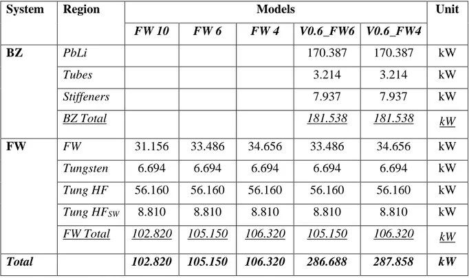
Table 4.2 – Eurofer thermo-physical properties (T in K) [47] ... 44 Table 4.3 – PbLi thermo-physical properties [64]... 45 Table 4.4 – Water thermo-physical properties (T in K) [47] ... 45 Table 4.5 – WCLL 2018 equatorial elementary cell geometrical parameters ... 52 Table 4.6 – WCLL 2018 V0 numerical models mesh statistics ... 54 Table 4.7 – WCLL 2018 design: power distribution divided by models and domains ... 57 Table 4.8 – WCLL 2018 V0 analyses boundary conditions ... 58 Table 4.9 – WCLL 2018 V0 analyses: main output parameters ... 60 Table 4.10 – WCLL stand-alone optimized FW system mesh independence analyses ... 72 Table 4.11 – WCLL FW systems optimization analyses mesh statistics... 72 Table 4.12 – WCLL V0.6 FW optimization power distribution divided by models and domains ... 75 Table 4.13 – WCLL V0.6 FW optimization analyses boundary conditions... 75 Table 4.14 – WCLL V0.6 FW optimization analyses: stand-alone main output parameters ... 76 Table 4.15 – WCLL V0.6 FW optimization analyses: complete system main output parameters ... 77 Table 4.16 – WCLL V0.6_FW4_R mesh statistic ... 91 Table 4.17 – WCLL V0.6_FW4_R BZ recirculation manifold boundary conditions ... 93 Table 4.18 – WCLL V0.6_FW4_R BZ recirculation manifold: maximum temperature ... 94 Table 4.19 – WCLL V0.6_FW4_R BZ recirculation manifold: water relevant parameters ... 94 Table 4.20 – WCLL V0.6_FW4_R BZ recirculation manifold pressure drops analytical estimation .... 95 Table 4.21 – WCLL V0.6 BZ and FW water main geometrical parameters ... 102 Table 4.22 – WCLL 2018 V0.6 layout heat transfer modelling approach: performed simulations ... 106 Table 4.23 – WCLL 2018 V0.6 layout heat transfer modelling approach: boundary conditions ... 108 Table 4.24 – WCLL 2018 V0.6 FEM model: mesh independence... 109 Table 4.25 – WCLL 2018 V0.6 layout heat transfer modelling approach: mesh statistics ... 110 Table 4.26 – WCLL 2018 V0.6 layout heat transfer modelling approach: Eurofer temperature ... 113 Table 4.27 – WCLL V0.6_FW4_R PbLi modelling comparison: performed analyses... 118 Table 4.28 – WCLL V0.6_FW4_R PbLi modelling comparison: boundary conditions divided by runs ... 119 Table 4.29 – WCLL V0.6_FW4_R PbLi modelling comparison: main outputs parameters ... 120 Table 4.30 – WCLL V0.6 tubes layout optimization different models and geometrical parameters .... 133 Table 4.31 – WCLL V0.6 tubes layout optimization mesh statistics ... 134 Table 4.32 – WCLL V0.6 tubes layout optimization power distribution divided by models and domains ... 136
Table 4.33 – WCLL V0.6 tubes layout optimization main output parameters [81] ... 138 Table 5.1 – WCLL V0.6 mesh independence statistics and results divided by ID ... 160 Table 5.2 – WCLL V0.6_B transient analysis B00 and BXX mesh statistics ... 161 Table 5.3 – WCLL V0.6_B transient analysis: performed run ... 171 Table 5.4 – WCLL V0.6_B transient analysis: power time interval and total time... 173 Table 5.5 – WCLL V0.6_B steady-state analysis: boundary conditions ... 174 Table 5.6 – WCLL V0.6_B transient analysis: boundary conditions ... 175 Table 5.7 – WCLL V0.6_B steady state analysis: relevant results ... 176 Table 5.8 – WCLL V0.6_B fast ramp-up transient initial and final temperature ... 179 Table 5.9 – WCLL V0.6_B ramp-down transient initial and final temperatures ... 186 Table 5.10 – WCLL V0.6_B low fluctuations transient initial and final temperatures ... 193 Table 5.11 – WCLL V0.6_B high fluctuations transient initial and final temperatures ... 202 Table 5.12 – WCLL V0.6_B thermal inertia transient initial and final temperatures ... 212
Table A.1 – Thermo-physical properties of Eurofer [97] ... 225 Table A.2 – Thermo-physical properties of Water [67] ... 226 Table A.3 – Thermo-physical properties of Tungsten [98] ... 227
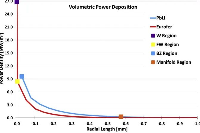
Table B.1 – Eurofer/Tungsten volumetric power deposition [58] ... 228 Table B.2 – PbLi volumetric power deposition [58] ... 229 Table B.3 – Fast ramp-up normalized power trend [94][95] ... 230 Table B.4 – Fast ramp-up FW water inlet temperature trend ... 231 Table B.5 – Fast ramp-up BZ water inlet temperature trend ... 232 Table B.6 – Ramp-down normalized power trend [94][95] ... 233 Table B.7 – Ramp-down FW water inlet temperature trend ... 234 Table B.8 – Ramp-down BZ water inlet temperature trend ... 235 Table B.9 – Low power fluctuations normalized power trend [83][84] ... 236 Table B.10 – High power fluctuations normalized power trend [83][84] ... 237 Table B.11 – Step-down ramp normalized power trend ... 237
1. INTRODUCTION
From a technical and economic perspective, energy is the commodity that allows a society to progress and develop. Nowadays, the development of a robust and reliable energy sector, able to promote a sustainable and secure energy solution is pivotal to every economic, environmental and developmental issue. The energy demand is expected to be more than double in 2050 [1], this will be caused by a constant increase of population and increasing use of energy per capita due to the use of products that are increasingly running on electricity and increasingly connected. Moreover, considering the progressive reduction of the use of fossil fuels, to mitigate the increase in greenhouse gases emission, as the CO2, as well as the necessity of cleaner ways to produce energy, the world population is forced to invest in the research for alternative power sources that can provide them a long-term sustainability, reliability and security. In compliance with this background, nuclear energy has become a considerable solution to solve the energy problem. Nuclear energy provides a large amount of energy in a comparative manner with fossil fuels, is carbon-free and with low variable costs. However, nuclear energy still has to solve problems as nuclear waste management, proliferation risks and safety during the severe accident. In this framework, nuclear fusion has several advantages over nuclear fission, if the technology will be successfully developed, so it has been selected as a research field where to make large investments. It has been considered as the most suitable solution to the energy problem. It will ensure sustainability and security of supply: fuels are widely available and virtually unlimited since they are processed from water; no production of greenhouse gases; intrinsically safe, as no chain-reaction is possible; environmentally responsible, with a proper choice of materials for the reaction chamber, radioactivity decays in a few tens of years and at around 100 years after the reactor shutdown all the materials can be recycled in a new life cycle. However, efforts still need to be done to engineer a system that can sustain the plasma for a period sufficient to reach very high temperatures and density and use materials that withstand to this particular environment.
During 2012, the EUROfusion’s previous organization [2], the European Fusion Development Agreement (EFDA), has published a roadmap which outlines hot to supply fusion electricity by 2050. The “Roadmap to the realization of fusion energy” [1] breaks the quest for fusion
These eight missions can briefly resume in:
1) Demonstrate plasma regimes of operation with ITER (based on the tokamak configuration);
2) Demonstrate a heat exhaust system capable of withstanding the large load of DEMO; 3) Develop materials that withstand large 14 MeV neutron fluence without degrading their
physical properties;
4) Ensure tritium self-sufficiency through a technological solution for the breeding blanket; which will have to be made consistently with the choice of the components for the transformation of the high-grade heat into electricity (the so-called Balance of Plant).
5) Implement the intrinsic safety features of fusion into the design of DEMO following the experience gained with ITER;
6) Combining all the fusion technologies into an integrated DEMO design; e.g. exploiting a complete BoP including the heat transfer and associated electrical generation systems; 7) Ensure the economic potential of fusion by reducing the DEMO capital costs and
developing long-term technologies; 8) Bring the stellarator line to maturity.
From an initial roadmap of 2012 where some dates were provided and foreseen, considerable technological challenges had to be faced, and for this reason, the roadmap has evolved in a new one, scheduled with: short, medium and long term. Precisely in 2018, a new “European Research Roadmap to the realization of fusion energy” [3] has been published, where ITER has been identified as the facility that will have to provide the greatest number of answers regarding the feasibility of fusion, and DEMO has been identified as the power plant reactor which will pave the way for commercial reactors. In addition, a characterization was given to the three main phases, where, the end of the short-term will be identified with the ITER first plasma ignition, the medium-term will end with the DEMO commence construction and it is where the long-term will starts, until the electricity production will be achieved.
The DEMO reactor must demonstrate the possibility of generating electricity through nuclear fusion reactions, although not in a cost-effective way as the commercial power plants.
Moreover, it must operate with technologies able not only to control the plasma but also to generate electricity as a safe and reliable power plant. The main challenge of the DEMO power plant will be to create and sustain a long-lasting plasma with a power 25 time higher than ITER, and moreover to maintain its stability to demonstrate the feasibility of the electricity production [4].
1.1. Framework of the activity
The Ph.D. research activity has been performed in the framework of a cooperation between the University of Rome – DIAEE (Department of Astronautic, Electrical and Energetic Engineering) and the ENEA Brasimone Research Center – Experimental Engineering Division (FSN-ING), under the coordination of the European Consortium for the Development of Fusion Energy (EUROfusion).
Since 2014, the EUROfusion Consortium manages and coordinates fusion research activities and it was established to succeed the European Fusion Development Agreement (EFDA). It has been funded by the Euratom agency, to pursue the stated goal of an operative DEMOnstration Fusion Power Plant (DEMO) in accordance with the roadmap for the realization of the fusion energy, in the frame of the Horizon2020 programme. In this context, the development of two alternative blanket designs is being studied in the DEMO pre-conceptual phase: the Helium Cooled Pebble Bed (HCPB), based on solid breeder technology, and the Water-Cooled Lithium Lead (WCLL), based on liquid breeder technology.
The EUROfusion Consortium agreement has been signed by thirty members research organizations and universities from 26 European Union countries plus Switzerland. Italy is one of the signatory members of EUROfusion Consortium and ENEA is the national Research&Development (R&D) agency that leads and coordinates the activities. This programme involves several universities and industries, one of these is the Sapienza University of Rome which is involved in different research activities. ENEA actively participates to the conceptual development of the DEMO power plant. In particular, at Experimental Engineering Division (FSN-ING) of ENEA C.R. Brasimone, R&D activities are pursued to develop the
1.2. Objectives of the thesis
The objectives of this thesis is to develop a conceptual design that can safely operate and satisfy the multiple DEMO requirements, which is also one of the open fields in the WCLL breeding blanket research activities. The BB is one of the key components of a nuclear fusion power plant, is in charge of ensuring the essential functions of Tritium production, generating the fuel necessary for the plant self-sustainment; shield the Vacuum Vessel (VV) from nuclear radiation that may impact essential reactor systems and personnel and superconducting coils in order to avoid quenching; remove the heat generated in the toroidal chamber by photons and neutrons interaction, converting in energy suitable for the electricity production.
This research activity has focused on developing the conceptual design of the WCLL from a thermal-hydraulic point of view, demonstrating the capability to fully satisfy the DEMO requirements. The goal is to be able to identify a configuration of the elementary cell that has to satisfy several design requirements concerning the structures and both cooling systems, the First Wall (FW) and the Breeding Zone (BZ). The requirements are listed below:
• Temperature symmetry in toroidal direction;
• Maximized cooling performances enhancing the water heat transfer coefficient; • Structures temperature below the imposed limit;
• Optimized number of BZ tubes reducing the amount of Eurofer into the BZ increasing the breeder volume which affect the Tritium production performances;
• Optimized number of FW channels reducing the amount of Eurofer and water into the FW which affect the Tritium production performances;
• Enhancing manufacturability avoiding pipes crossing structural stiffeners.
Based on these points, a preliminary review of the previous WCLL configurations has been studied, highlighting the advantages and issues of the different configurations. Both have shown achieved goals but in conflict with other points. It was necessary to study these results and to engineer them, even if taken individually they seemed disparate, to analytically develop an elementary cell which can satisfy all these requirements. This process led to the creation of a
layout named WCLL 2018 V0.2. To better understand the feasibility of this innovative layout, a three-dimensional finite volume model of the elementary cell has been set-up, using the CFD code ANSYS CFX v18.2. The model fully reproduces in detail the WCLL elementary cell, composed of solid and fluid domains. From this CFD model, the optimization process of the BZ and FW systems has begun. Several analyses have been performed to investigate thermal and fluid-dynamic behavior of the breeding cell, to optimize and evaluate the efficiency of the FW and BZ water cooling systems, and to verify if the maximum temperature of solid structures were in the allowed limits. Moreover, after each analysis, key issues and areas of improvements are highlighted for further optimization. Once the number of tubes and channels has been optimized, efforts have been made to improve the efficiency of the cooling system, optimizing temperature distribution, reducing the tubes wall temperature to avoid thermal crisis and enhancing the water thermal-hydraulic performances.
This process has led to obtaining the WCLL 2018 V0.6 layout, which operates with twenty-two BZ tubes with an alternative manifold that adopts the recirculation and four FW channels in alternate and opposite flows. In order to verify the effective efficiency of the systems, conservative boundary conditions have been implemented in CFX, so as to confirm the choice made and the solutions adopted. These analyses led to further optimization of the layout, modifying the layout of the tubes due to the hot-spots onset into the structures exceeding the imposed limit. The final selected design has been confirmed through the numerical simulation, returning a model that faces the imposed requirements. The configuration is named WCLL V0.6_B.
The second part of the activity has the objectives to verify if the elementary cell WCLL V0.6_B is able to withstand the postulated operational phases of the DEMO power plant. In this part, transient CFD analyses have been performed, which require a significantly higher computational cost. This implies that in order to obtain results in a reasonable time, it has been deemed mandatory to reduce the number of elements in the numerical model. The main goal of these analyses has been switched in investigating the global performances of the elementary cell with its related cooling systems and the temperature field of the structures. The pulsed nature of the DEMO fusion reactor divides the operative phase in two main phases: the Pulse where the Deuterium and Tritium are burnt and energy is produced for 120 min, and the Dwell
operation, this causes peaks of over or under power. In addition, a comparison between the obtained data and the data provided by the analysis done in the Balance of Plant Work Package (WPBoP), has been done. The comparison laying the basis to understand the commercial feasibility of the reactor with the postulated off-reactor systems necessary to produce and provide electricity to the grid.
The research activity has led to the development of a complete conceptual design of WCLL breeding blanket elementary cell, that fully satisfy the DEMO design requirement. Moreover, the configuration fully withstands the DEMO thermal-loads postulated in normal and off-normal operation and deals with the pulse nature of the reactor with its plasma instabilities.
1.3. Thesis structures
This Ph.D. thesis is structured in six sections. The first section includes a brief introduction, the framework and objectives of the research activity, whereas the sixth section presents the conclusions and perspectives.
An overview of the nuclear fusion technologies, DEMO reactor with its components, fuel cycle and breeding blanket concepts are described in the second section.
The third section describes in detail the Water-Cooled Lithium Lead Breeding Blanket. It starts with a brief review of the previously analyzed blanket concepts, which led to the development of the actual configuration. In the subsections, the actual WCLL configuration is described, with its main functions, requirements and limits. In addition, FW, BZ and Manifold regions are widely discussed, describing their functions and design. In the last part the main achievement and issues of the WCLL 2018 V0.2 are pointed out.
In the fourth section, the first part of the numerical simulations is reported. Thermal-hydraulic steady state analyses are performed starting from the elementary cell layout described in the previous section (WCLL 2018 V0.2). The three-dimensional finite volume model of the
elementary cell has been developed to perform the CFD simulation. Several studies are carried out regarding: the optimization of the BZ tubes layout and FW channels; evaluation of the impact of an alternative BZ manifold; investigation of the PbLi modelling impact with its related thermal properties; realization of a design that meets all DEMO requirements during the normal operation. The last subsection showed an elementary cell design (V0.6_B) which is able to face the steady state operational phase of the DEMO reactor.
Then, in the second numerical part (fifth section), a validation of the selected design is performed through transient thermal-hydraulic analyses. The different operational phases of the reactor are analyzed to verify if the selected design can sustain the operative pulsed behavior of DEMO reactor, evidencing peculiarities or issues.
The current nuclear power plants produce energy with a process in which a heavy nucleus, mainly uranium, collides with a subatomic particle, neutron, producing new lighter nuclei and subatomic particles. This process is called nuclear fission, and when one single nuclear reaction causes other subsequent nuclear reactions, thus leads to a self-propagation through a chain process. The opposite process, that allows two light nuclei to collide and fuse together into a heavier nucleus, is the nuclear fusion. In both case, nuclear reactions, in accordance with the mass-energy conservation principle, are accompanied by a net energy release; thus, the missing mass is transformed into energy, in accordance with the famous Einstein’s equation 𝐸 = 𝑚𝑐2 formulated in 1905. The energy release depends on the type of the nucleus/nuclei and, therefore, on the type of performed reaction. Since the nuclei, lighter than iron, have an energy release with fusion reactions and heavier than iron release energy with fission reactions.
2.1. Nuclear fusion technology
Fusion reaction is the process that powers the stars, it occurs spontaneously, given the reached very high temperatures [5]. To originate a nuclear fusion reaction, two nuclei have to collide with enough energy to overcome the mutual repulsive Coulombian force acting between them, approaching each other sufficiently close that the short-range attractive nuclear force becomes dominant. In order to provide enough energy to the nuclei, to approach and fuse together, overcoming the Coulombian force, kinetic energy is increased by heating up to temperatures around 100 millions of degrees [6]. At these temperatures, the matter is no longer in a gaseous state but in a plasma state. Once temperature reaches the order of 10000 degrees, the electrons detach from nuclei forming an ionized gas where naked charged nuclei and free electrons move independently, being so energized that they don’t combine, this state of matter is called plasma.
The reaction identified as the most suitable for fusion reactors involves two heavy hydrogen isotopes, Deuterium (D) and Tritium (T), described by the expression:
which produce a total amount of energy of 17.6 MeV. This reaction is characterized by the highest reactivity at the lowest temperature of all relevant reactions [6]. In order to be able to obtain this reaction, the fuel (i.e. Deuterium and Tritium) must be heated to temperature over 5·107 degrees before achieving a significant fusion rate.
Since fusion has been discovered in the 30s of the past century, the hardest challenge was to be able to create a machine capable of reaching such temperatures to heat the fuel and to confine it for a sufficiently long time, enough to produce through fusion reactions, more energy than was spent on heating the plasma [6]. During these years various types of machine have been studied to heat and confine the plasma, which differs by the types of confinement. Two of these have gathered the greatest interest and are the inertial and the magnetic confinement. In the former, a small pellet of D-T fuel is subjected to a high pulse flow of highly powerful laser that creates a high-density plasma instantly increasing the temperature of the pellet providing a favorable fusion reaction rate for few nanoseconds. The second approach, which is the one on which the investments are focusing, uses strong magnetic fields to confine the plasma in a vacuum environment with a toroidal shape, named tokamak [7].
2.1.1. Magnetic confinement
In a fusion reactor, which works with a tokamak magnetic confinement, the reactions take place inside the plasma, confined in the toroidal chamber. The charged particles are subjected to the magnetic field by Lorentz force, which determines their trajectory. Imposing a magnetic field to the torus chamber, the particles start to orient with the magnetic field line and move with a path, in accordance with the field lines, in the toroidal chamber with no escapes. However, the motion will tend to diverge to the outer plasma edge escaping from the plasma; this is due to the centrifugal force, which must be balanced with the Lorentz one. To ensure that all forces are balanced, two different magnetic fields are applied: toroidal and poloidal; this establishes a helical path, perpendicular to the torus axis, avoiding that charged particles escape from the plasma. In addition, a central solenoid coil is placed in the central hole of the tokamak to induce the plasma current which acts as a starter for the plasma’s ignition. In Fig. 2.1 a schematic diagram showing the working principles of the tokamak magnetic configuration is shown.
Fig. 2.1 – Tokamak magnetic confinement working principles [8]
To reach the sufficient conditions to obtain fusion reactions, the plasma current is not enough, and even if the Helium produced by the D-T reaction remain in the plasma transferring its energy to it, additional systems are necessary to heat the plasma and balance the thermal losses, such as: neutral beam injection, radiofrequency heaters and current drive.
Currently, the largest European tokamak is the Joint European Torus JET [9], which has reached the breakeven point with a gain factor of Q=1, where the energy spent is equal to the energy produced. The demonstration of high-power fusion reactor with a Q≥10 is the main mid-term goal, which will have to be proved by the International Thermonuclear Experimental Reactor ITER [3][8], which is actually under construction in France and will be the first large scale reactor. Once ITER will demonstrate the feasibility of a sustainable fusion reactor [10], the construction of the DEMOnstration Fusion Power Plant DEMO will begin to demonstrate the successive steps: the electricity supply to the grid and the realization of a closed fuel cycle [2][3].
2.2. DEMO reactor and components
The DEMO reactor relies on the tokamak magnetic confinement, with Deuterium and Tritium as fuel. The hot plasma, where the D-T reaction occurs, is held in a thermally insulated chamber, the Vacuum Vessel (VV). As described in the section above, the D-T reaction has, as reaction product, Helium and neutron; the Helium heats the plasma, but neutron is intensely energetic and it is very difficult to contain into the plasma or even in the VV, it bombards the structural components and causes severe damages and activation products. Neutrons are essentials for the reactor operation, due to their high energy that can be extracted and the possibility to close the fuel cycle with a breeding operation.
To obtain a lasting fusion reaction, different systems are necessary to create, control and monitor the plasma. These systems must also provide a protection and mitigation for human and plant safety, containing the reaction products, radionuclides and thermal power. Different and structured confinement are adopted, ensuring an adequate shielding. These containments can be identified in three main groups, where, within them contain multiple systems [11]. The principal three confinement and their related systems of DEMO are described in the following [10]-[14]:
• Vacuum Vessel (VV): is a torus-shaped double-walled pressure vessel. It encloses the plasma chamber, and provides a high-vacuum environment, with very high purity, which improves the plasma stability, must withstand high temperature to shield and maintain radionuclides and neutron inside the reactor. It also shields the Magnets System. The VV houses the in-vessel components and systems:
o Breeding Blanket (BB): DEMO is subdivided into 16 sectors with two inboard (IB) and three outboard (OB) segments each. Each segment is composed by the First Wall (FW) that is a plasma-facing component integrated with the blanket. It must withstand to high heat loads and radiation that arise from the plasma, is actively cooled to refrigerate the structures and to transfers the heat loads for the electricity production;
and the Breeding Zone (BZ), placed behind the FW, it contains Lithium to breed into Tritium due to the neutron radiation, ensuring the reactor fuel self-sufficiency. It is refrigerated by one coolant that can be Helium or water, to cool
causes that the field lines impact the Divertor targets, collecting and removing the spent Helium ashes and impurities from plasma. Is subjected to the highest heat loads and the particle impact causes the most severe erosion.
• Magnets System (MS): is an assembly of superconducting coils (SC) which provide the magnetic field to confine the plasma, driving its current and defining its poloidal structure. The magnets are composed by Low-Temperature Super Conducting Nb3Sn,
and are divided in three different coils group:
o Toroidal Field Coils (TFC): powered by a constant current which provides the toroidal field;
o Poloidal Field Coils (PFC): powered by a current that change over the plasma operation, they provide the poloidal and radial magnetic field and improve the plasma stability;
o Central Solenoid (CS): is a stack of coils in the hole of the torus, it induces the plasma current by discharging itself;
• Cryostat: is a large single-walled, passively cooled vacuum vessel at the ambient temperature, placed outside the VV and MS, containing them. It provides the high-vacuum and very low-temperature environment necessary for the magnets and the plasma chamber.
Fig. 2.2 – DEMO reactor general layout [12]
Several other relevant systems are necessary to obtain a fusion reaction. External heating systems are necessary to reach the high plasma temperature, employing: injection of neutral beams (NBI) into the plasma, transferring their energy to it; electromagnetic waves, Electron Cyclotron Heating (ECH) and Ion Cyclotron Heating (ICH). These three systems also provide additional functions as control and current drive. Another fundamental system is the Tritium Extraction System [14], that is tasked for the removal of the Tritium from the breeder, which aims at the tritium self-sufficiency, to restore in the reactor as fuel supplies.
Two different structural materials are adopted in DEMO [13], the first one is employed for the in-vessel components, is named Reduced Activation Ferritic Martensitic (RAFM) steel Eurofer, which must be refrigerated below temperatures of 550°C in order to ensure adequate thermo-mechanical properties. The second one is the AISI ITER-grade 316 stainless steel that is adopted for the VV.
Due to the necessity to provide a long-lasting plasma current, to guarantee the plasma stability, the DEMO fusion reactor works with two different phases alternate, being a pulsed regime machine. The first phase is the burning phase, is when the plasma is generated and the fuel is burnt inside the chamber producing nuclear reactions, thus energy. The second phase is the
Equatorial port Lower port Upper port Central solenoid Poloidal field coils Divertor Toroidal field coils Inboard blanket
segment
Outboard blanket segment
building a grid-connected plant. The turbines, for electricity production, work in a continuous regime, and this pulsed behavior is deleterious to their life. To address this problem, a complex system’s chain, which is devoted to the power extraction from the plasma and its conversion into electricity to deliver to the grid, has been adopted. The chain has, as first, the Primary Heat Transfer System (PHTS), that is responsible of converting the energy collected in the blanket by both cooling systems. The PHTS, followed by the Power Conversion System (PCS), ensure the electricity production during the burning phase. An Intermediate Heat Transport System (IHTS), which is placed between the PHTS and the PCS, operates in both phases, pulse and dwell. The IHTS is provided by an Energy Storage System (ESS), which accumulates energy during the pulse phase and releases during the dwell, to smooth the pulsed behavior producing a continuous conversion/production of electricity [15][16].
There are still many engineering and physical challenges that will have to be faced, more information on the open issues can be found in Refs. [17][18].
2.3. Fuel cycle
The D-T fusion reaction has been selected as a characteristic reaction on which tokamaks are based, due to its highest reactivity at the lowest temperature and to the availability of the fuel supply. Deuterium is the second most abundant hydrogen isotope, it exists in seawater at 0.0153% and can be extracted from it, a source with availability practically inexhaustible. Tritium, instead, is radioactive and undergoes beta decay in 3He with a half-life of 12.5 yr, following the reaction:
𝑇13 → 𝐻𝑒23+ 𝛽−+ 𝑣̅𝑒+ 18.6 𝑘𝑒𝑉
Its short half-life makes Tritium extremely rare on Earth and no industrial exploitation from a natural source is economically feasible. Achieving the Tritium self-sufficiency is a key issue in the development of a self-sustaining fusion reactor which operates with D-T fuel.
Actually, Tritium is artificially produced as product of the CANDU fission reactor operations, where it is generated by the irradiation of the moderator, which is heavy water (D2O). Moreover,
the quantity produced is useless for a large-scale reactor as DEMO, and in addition, a closed fuel cycle is one of the key points of the fusion realization roadmap; thus, the supply of Tritium cannot be dependent on the CANDU operations.
The chosen option to face this problem is to generate Tritium in the reactor through the breeding blanket, exploiting the high energy neutrons (14MeV), which derive from the fusion reactions, via capture reaction with Lithium, which is the breeder, as reported in the reactions below:
𝑛0+ 𝐿𝑖36 → 𝐻𝑒24+ 𝑇13+ 4.8 𝑀𝑒𝑉 𝑛0+ 𝐿𝑖37 → 𝐻𝑒24+ 𝑇13+ 𝑛0− 2.5 𝑀𝑒𝑉
The first reaction has a large cross section for thermal neutron, while the second reaction is more probable with fast neutrons. For this purpose, the breeder must be enriched up to 90% of
6Li. Unfortunately, the fusion reactions have a low neutron production rate (1 per reaction), this
implies that a neutron multiplier is necessary to face the neutron losses, due to capture or absorption, and to obtain a self-sufficient Tritium production. Therefore, the blanket is filled with the breeder and the neutron multiplier. The latter can be Beryllium or Lead, depending on which BB concepts is adopted. The R&D activities are actually focused on two different breeding blanket concepts: the Helium Cooled Pebble Bed (HCPB), based on solid breeder technology, and the Water Cooled Lithium Lead (WCLL), based on liquid breeder technology.
The realization of a closed fuel cycle passes through another engineering challenge: a highly efficient Tritium production in order to generate a surplus of it in a reasonable time to start a new reactor [19]. The reasonable time is expected to be around 5 years; in this regards it has been defined an important parameter, the Tritium Breeding Ratio (TBR). It is the ratio between the Tritium generated into the breeder and the Tritium burnt in the D-T reaction. The TBR is a complex parameter, composed by different and many reactor variables, which include radioactive decay, losses due to Tritium permeation, accumulation for a new reactor, failure of an extraction system. Concerning these uncertain variables, it has been set for DEMO a TBR ≥ 1.15 to achieve the tritium self-sufficiency [20].
the VV from neutron and radiation and accumulates energy, generated into the plasma via thermal radiation and neutrons interactions, transforming into thermal energy. The latter is removed by means of cooling systems, which convey this energy to the PHTS, where is converted into electricity through a turbine.
Different blanket concepts are and have been studied in the last years, but they can be classified in two different main categories, solid breeder and liquid breeder, which still remains Lithium. Since 2014, four different blanket concepts have been selected to address the role of breeding blanket in the DEMO reactor [21]: the Helium Cooled Pebble Bed (HCPB), the Helium Cooled Lithium Lead (HCLL), the Dual Coolant Lithium Lead (DCLL) and the Water Cooled Lithium Lead (WCLL). The former and the last are the more promising two blanket concepts, currently under study, one with a solid breeder and other with a liquid one respectively. Therefore, the EUROfusion consortium has decided to continue to develop only the HCPB and the WCLL, to the detriment of the HCLL and DCLL. These blanket concepts will be outlined in Sections 2.4.1 and 2.4.2, and regarding the WCLL it will be outlined in Section 3.
The two blanket concepts, the HCPB and the WCLL, have a similar architecture and design features, imposed by the use of a common DEMO 2017 baseline [10]. They are both characterized by 16 sectors, each including two inboard and three outboard BB segments. They also adopt Eurofer as a structural material. Given the advantages obtained for the WCLL [22], both designs have been developed on the basis of the Single-Module-Segment (SMS) approach. Each segment consists of a long continuous Eurofer chase external box, composing the FW system, which develops along the entire poloidal length with a bottom and a top cap. In addition, both have provided a Back Plate (BP), which divide the BZ system with the manifold region. Each segment is supported by a Back Supporting Structure (BSS), which connects the BB to the VV [14].
![Fig. 3.8 – WCLL blanket concept 2017 half equatorial elementary cell geometry: vertical stiffeners (left) and horizontal stiffeners (right) [55]](https://thumb-eu.123doks.com/thumbv2/123dokorg/2885318.10763/55.892.135.808.376.571/blanket-equatorial-elementary-geometry-vertical-stiffeners-horizontal-stiffeners.webp)
![Fig. 3.9 – WCLL blanket concept 2017 – different elementary cell configurations and BZ tubes layout (ENEA) [55] T02T03 Tor RadPolRadTorRadPol](https://thumb-eu.123doks.com/thumbv2/123dokorg/2885318.10763/56.892.129.802.128.1111/wcll-blanket-concept-different-elementary-configurations-layout-radpolradtorradpol.webp)
![Fig. 4.12 – WCLL FW system COB equatorial model with different number of channels [71]](https://thumb-eu.123doks.com/thumbv2/123dokorg/2885318.10763/96.892.131.810.124.421/fig-wcll-cob-equatorial-model-different-number-channels.webp)