PAPER
Vibration isolation system with a compact damping
system for power recycling mirrors of KAGRA
To cite this article: Y Akiyama et al 2019 Class. Quantum Grav. 36 095015
View the article online for updates and enhancements.
Recent citations
Overview of KAGRA: Detector design and construction history
T Akutsu et al
-Compact integrated optical sensors and electromagnetic actuators for vibration isolation systems in the gravitational-wave detector KAGRA
Tomotada Akutsu et al
-An arm length stabilization system for KAGRA and future gravitational-wave detectors
T Akutsu et al
-1 Classical and Quantum Gravity
Vibration isolation system with a compact
damping system for power recycling
mirrors of KAGRA
Y Akiyama1, T Akutsu2, M Ando3, K Arai4, Y Arai4, S Araki5,
A Araya6, N Aritomi7, H Asada8, Y Aso9, S Bae10, L Baiotti11,
M A Barton2, K Cannon12, E Capocasa2, C-S Chen13,
T-W Chiu13, K Cho14, Y-K Chu13, K Craig4, V Dattilo15,
K Doi16, Y Enomoto3, R Flaminio2, Y Fujii17, M-K Fujimoto2,
M Fukunaga4, M Fukushima18, T Furuhata16, S Haino19,
K Hasegawa4, Y Hashimoto1, K Hashino16, K Hayama20,
T Hirayama1, E Hirose4, B H Hsieh4, C-Z Huang13,
B Ikenoue18, Y Inoue19, K Ioka21, Y Itoh22, K Izumi23, T Kaji22,
T Kajita4, M Kakizaki16, M Kamiizumi24, S Kanbara16,
N Kanda22, S Kanemura11, G Kang10, J Kasuya25, N Kawai25,
T Kawasaki3, C Kim26, W S Kim27, J Kim28, J C Kim29,
N Kimura5, S Kirii24, Y Kitaoka22, H Kitazawa16, Y Kojima30,
K Kokeyama24, K Komori3, A Kong31, K Kotake20, R Kozu24,
R Kumar32, H-S Kuo13, S Kuroki2, S Kuroyanagi33, H K Lee34,
H M Lee35, H W Lee29, M Leonardi2, C-Y Lin36, F-L Lin13,
G C Liu37, M Marchio2, T Matsui38, Y Michimura3, N Mio39,
O Miyakawa24, A Miyamoto22, S Miyoki24, W Morii40,
S Morisaki12, Y Moriwaki16, M Musha41, S Nagano42,
K Nagano4, K Nakamura2, T Nakamura43, H Nakano44,
M Nakano4, T Narikawa43, L Nguyen Quynh45, W-T Ni46,
A Nishizawa33, Y Obuchi18, J Oh27, S H Oh27, M Ohashi24,
N Ohishi9, M Ohkawa47, K Okutomi48, K Ono4, K Oohara49,
C P Ooi3, S-S Pan50, F Paoletti51, J Park14, R Passaquieti51,52,
F E Peña Arellano24, N Sago53, S Saito18, Y Saito24, K Sakai54,
Y Sakai49, M Sasai22, S Sato1, T Sato47, T Sekiguchi1,
Y Sekiguchi55, M Shibata21, T Shimoda3, H Shinkai56,
T Shishido57, A Shoda2 , N Someya1, K Somiya25, E J Son27,
A Suemasa41, T Suzuki47, T Suzuki4, H Tagoshi4, H Tahara58,
H Takahashi59, R Takahashi2, H Takeda3, H Tanaka4,
K Tanaka22, T Tanaka43, S Tanioka48, E N Tapia San
Martin2, T Tomaru5, T Tomura24, F Travasso60, K Tsubono3,
S Tsuchida22, N Uchikata61, T Uchiyama24, T Uehara62,63,
K Ueno12, F Uraguchi18, T Ushiba4, M H P M van Putten64,
H Vocca60, T Wakamatsu49, Y Watanabe49, W-R Xu13,
Y Akiyama et al
Vibration isolation system for power recycling mirrors of KAGRA
Printed in the UK
095015
CQGRDG
© 2019 IOP Publishing Ltd 36
Class. Quantum Grav.
CQG 1361-6382 10.1088/1361-6382/ab0fcb Paper 9 1 16
Classical and Quantum Gravity
2019
1361-6382/19/095015+16$33.00 © 2019 IOP Publishing Ltd Printed in the UK
T Yamada4, K Yamamoto16, K Yamamoto4, S Yamamoto56,
T Yamamoto24, K Yokogawa16, J Yokoyama12, T Yokozawa24,
T Yoshioka16, H Yuzurihara4, S Zeidler2 and Z-H Zhu65
1 Graduate School of Science and Engineering, Hosei University, Koganei, Tokyo 184-8584, Japan
2 National Astronomical Observatory of Japan, Mitaka, Tokyo 181-8588, Japan 3 Department of Physics, The University of Tokyo, Bunkyo, Tokyo 113-0033, Japan 4 Institute for Cosmic Ray Research (ICRR), The University of Tokyo, Kashiwa, Chiba 277-8582, Japan
5 High Energy Accelerator Research Organization, Tsukuba, Ibaraki 305-0801, Japan 6 Earthquake Research Institute, The University of Tokyo, Bunkyo, Tokyo 113-0032, Japan
7 Department of Physics, University of Tokyo, Bunkyo, Tokyo 113-0033, Japan 8 Department of Mathematics and Physics, Hirosaki University, Hirosaki, Aomori 036-8561, Japan
9 National Astronomical Observatory of Japan, Hida, Gifu 506-1205, Japan
10 Korea Institute of Science and Technology Information, Yuseong, Daejeon 34141, Republic of Korea
11 Department of Physics, Osaka University, Toyonaka, Osaka 560-0043, Japan 12 Research Center for the Early Universe (RESCEU), The University of Tokyo, Bunkyo, Tokyo 113-0033, Japan
13 Department of Physics, National Taiwan Normal University, Taipei 116, Taiwan, Republic of China
14 Department of Physics, Sogang University, Seoul 121-742, Republic of Korea 15 European Gravitational Observatory (EGO), I-56021 Cascina, Pisa, Italy 16 Department of Physics, University of Toyama, Toyama, Toyama 930-8555, Japan 17 Department of Astronomy, The University of Tokyo, Bunkyo, Tokyo 113-0032, Japan
18 Advanced Technology Center, National Astronomical Observatory of Japan, Mitaka, Tokyo 181-8588, Japan
19 Institute of Physics, Academia Sinica, Nankang, Taipei 11529, Taiwan, Republic of China
20 Department of Applied Physics, Fukuoka University, Jonan, Fukuoka 814-0180, Japan
21 Yukawa Institute for Theoretical Physics, Kyoto University, Sakyo, Kyoto 606-8502, Japan
22 Graduate School of Science, Osaka City University, Sumiyosi, Osaka 558-8585, Japan
23 Institute of Space and Astronautical Science, Japan Aerospace Exploration Agency, Sagamihara, Kanagawa 252-5210, Japan
24 Institute for Cosmic Ray Research (ICRR), The University of Tokyo, Hida, Gifu 506-1205, Japan
25 Graduate Schoool of Science and Technology, Tokyo Institute of Technology, Meguro, Tokyo 152-8551, Japan
26 Department of Physics, Ewha Womans University, Seodaemun-gu, Seoul 03760, Republic of Korea
27 National Institute for Mathematical Sciences, Daejeon 34047, Republic of Korea 28 Department of Physics, Myongji University, Yongin 449-728, Republic of Korea 29 Department of Computer Simulation, Inje University, Gimhae, Gyeongsangnam 50834, Republic of Korea
30 Department of Physical Science, Hiroshima University, Higashihiroshima, Hiroshima 903-0213, Japan
31 Department of Physics and Institute of Astronomy, National Tsing Hua University, Hsinchu 30013, Taiwan, Republic of China
32 California Institute of Technology, Pasadena, CA 91125, United States of America 33 Institute for Advanced Research, Nagoya University, Nagoya, Aichi 464-8602, Japan
34 Hanyang University, Seoul 133-791, Republic of Korea
35 Department of Physics and Astronomy, Seoul National University, Seoul 08826, Republic of Korea
36 National Center for High-performance computing, National Applied Research Laboratories, Hsinchu 30076, Taiwan, Republic of China
37 Department of Physics, Tamkang university, Danshui Dist., New Taipei City 25137, Taiwan, Republic of China
38 School of Physics, Korea Institute for Advanced Study (KIAS), Seoul 02455, Republic of Korea
39 Institute for Photon Science and Technology, The University of Tokyo, Bunkyo, Tokyo 113-8656, Japan
40 Disaster Prevention Research Institute, Kyoto University, Uji, Kyoto 611-0011, Japan
41 Institute for Laser Science, University of Electro-Communications, Chofu, Tokyo 182-8585, Japan
42 The Applied Electromagnetic Research Institute, National Institute of Information and Communications Technology (NICT), Koganei, Tokyo 184-8795, Japan
43 Department of Physics, Kyoto University, Sakyo, Kyoto 606-8502, Japan 44 Faculty of Law, Ryukoku University, Fushimi, Kyoto 612-8577, Japan
45 Department of Physics, University of Notre Dame, Notre Dame, IN 46556, United States of America
46 Wuhan Institute of Physics and Mathematics, Xiaohongshan, Wuhan 430071, People’s Republic of China
47 Department of Electrical and Electronic Engineering, Niigata University, Nishi, Niigata 950-2181, Japan
48 The Graduate University for Advanced Studies, Mitaka, Tokyo 181-8588, Japan 49 Graduate School of Science and Technology, Niigata University, Nishi, Niigata 950-2181, Japan
50 Center for Measurement Standards, Industrial Technology Research Institute, Hsinchu, 30011, Taiwan, Republic of China
51 INFN, Sezione di Pisa, I-56127 Pisa, Italy 52 Universit a di Pisa, I-56127 Pisa, Italy
53 Faculty of Arts and Science, Kyushu University, Nishi, Fukuoka 819-0395, Japan 54 Department of Electronic Control Engineering, National Institute of Technology, Nagaoka College, Nagaoka, Niigata 940-8532, Japan
55 Faculty of Science, Toho University, Funabashi, Chiba 274-8510, Japan 56 Faculty of Information Science and Technology, Osaka Institute of Technology, Hirakata, Osaka 573-0196, Japan
57 The Graduate University for Advanced Studies, Tsukuba, Ibaraki 277-8583, Japan 58 Kavli Institute for the Physics and Mathematics of the Universe, Kashiwa, Chiba 277-8583, Japan
59 Department of Information and Management Systems Engineering, Nagaoka Uni-versity of Technology, Nagaoka, Niigata 940-2188, Japan
60 Istituto Nazionale di Fisica Nucleare, University of Perugia, Perugia 06123, Italy 61 Faculty of Science, Niigata University, Nishi, Niigata 950-2181, Japan
62 Department of Communications, National Defense Academy of Japan, Yokosuka, Kanagawa 239-8686, Japan
63 Department of Physics, University of Florida, Gainesville, FL 32611, United States of America
64 Department of Physics and Astronomy, Sejong University, Gwangjin, Seoul 143-747, Republic of Korea
65 Department of Astronomy, Beijing Normal University, Beijing 100875, People’s Republic of China
E-mail: [email protected]
Received 4 December 2018, revised 26 February 2019 Accepted for publication 14 March 2019
Published 12 April 2019 Abstract
A vibration isolation system called the Type-Bp system used for power recycling mirrors has been developed for KAGRA, the interferometric gravitational-wave observatory in Japan. A suspension of the Type-Bp system passively isolates an optic from seismic vibration using three main pendulum stages equipped with two vertical vibration isolation systems. A compact reaction mass around each of the main stages allows for achieving sufficient damping performance with a simple feedback as well as vibration isolation ratio. Three Type-Bp systems were installed in KAGRA, and were proved to satisfy the requirements on the damping performance, and also on estimated residual displacement of the optics.
Keywords: gravitational waves, gravitational wave detector, KAGRA, vibration isolation, control
(Some figures may appear in colour only in the online journal)
1. Introduction
The first detection of the gravitational waves (GWs) from the binary black hole in 2015 [1] opened a new era of GW astronomy. Furthermore, the sky localization of the GW sources by the LIGO–Virgo joint observation enabled us to observe the electromagnetic counterpart, which revealed further information about the compact binary [2]. In order to improve the parameter estimation accuracy such as polarization of the GWs [3], it is important to construct the GW observation network with more than three detectors. Having more detectors also has the advantage of increasing the observation rate.
KAGRA as a fourth detector is now under construction in Japan [4]. It is a GW detector with 3 km scale cryogenic interferometer constructed underground. KAGRA is expected to join the GW observation network within next few years [5]. In addition, KAGRA employs the advanced features, such as construction in underground as a quiet environment, and cryogenic mirrors for thermal noise reduction.
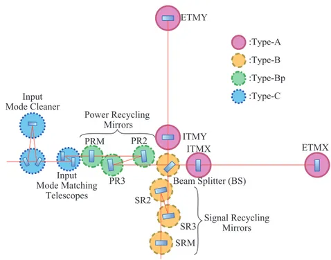
Figure 1 shows the configuration of the main optics in KAGRA. Each mirror is suspended as a pendulum for vibration isolation. The pendulum-type vibration isolation system isolates a mirror from the ground motion above the resonant frequencies of the pendulum. The amount of vibration isolation is further increased by using long suspensions and multiple stages.
On the other hand, the mirror swings with a large amplitude at their resonant frequencies. It is essential for stable operation of the GW observatory to reduce the large motion of the optics at the resonant frequencies of the suspensions. For example, quick recovery from the large disturbance due to earthquakes or control failures using the damping system can increase the duty cycle.
In this paper, we will introduce a vibration isolation system with a newly designed mechan-ics for the damping control for power recycling mirrors in KAGRA, which is called Type-Bp system. This damping system is rather small, but has the sufficient performance to damp almost all the resonant modes properly.
2. Vibration isolation systems in KAGRA
2.1. KAGRA suspension overview
Circles in figure 1 represent the type of the vibration isolation system used for each mirror. We have four types of vibration systems according to their requirements on residual displacement of each mirror. They are called Type-A, -B, -Bp, and -C systems as shown in figure 2.
A suspension of the Type-A system is used for the test masses that are most critical for the GW detection. It has the longest tower with a height of about 13 m at room temperature, and a payload working at temperature below 20 K at the four bottom stages. From a pre-isolator unit composed of inverted pendulums (IPs) and a geometrical anti-spring (GAS) filter, four room-temperature stages equipped with a GAS filter inside are suspended. The IP effectively reduces the micro seismic motion that has large amplitude at around 0.3 Hz, since its resonant frequency is as low as 80 mHz. GAS filters are implemented in order to isolate the mirror from the vertical seismic motion. At the bottom, four cryogenic stages including a test mass
ETMY ITMY ITMX ETMX Beam Splitter (BS) SR2 SR3 SRM PR2 PR3 PRM Input Mode Matching Telescopes Input Mode Cleaner Power Recycling Mirrors Signal Recycling Mirrors :Type-Bp :Type-C :Type-B :Type-A
mirror are suspended. Type-B is used for beam splitter (BS) and signal recycling (SR) mir-rors. This suspension has a pre-isolator unit at the top similarly to the suspension of Type-A, while it has only two GAS filter stages below. The intermediate mass (IM) is suspended from the GAS spring, and the intermediate recoil mass (IRM) is from the base plate of the spring, independently. And from the IM, the optics and the recoil mass (RM) are suspended inde-pendtly as well [6]. The power recycling (PR) mirrors are suspended by suspensions of the Type-Bp system. Unlike the Type-B system, they do not have the pre-isolator unit because of the constraint on the available space in vacuum chambers. A suspension of the Type-C system, a double-stage pendulum, is used for the rather small mirrors, such as the input mode cleaners and the mode matching telescopes. Its design is the same as the one used in TAMA300 [7]. 2.2. Requirement on Type-Bp and simulated results
The vibration isolation system has requirements on its performance mainly in four aspects: displacement of the optic in KAGRA’s observation band, 1/e decay time of the resonant modes, root mean square (RMS) of the velocity of the optic, and RMS of the residual angular fluctuation of the optic. The suspension system has to damp the resonant mode enough as well as to reduce the motion of the optic due to the seismic motion and noise induced from the damping control. The displacement of the optic has to be recovered back to the state where the interferometer can be operated soon enough even after the large disturbance caused by earthquakes or failures of interferometer control. During the alignment of the interferometer, the orientation of each optic has to be controlled so that the laser beam stably hits at almost the center of the optic at 3 km away. Also, the optics have to have small enough momentum to acquire the control of the optical cavity. If an optic swings too fast, the actuators cannot capture the optic at an optical resonance point while the optic passes through.
Table 1 is a summary of the requirements on the PR mirrors. Since the requirement on the displacement of the PR mirrors are about 300 times larger than that of the SR mirrors [8, 9], Type-Bp suspension is reasonably compact and simple. The commissioning of the suspension control is much simpler than other suspensions since the Type-Bp suspension does not have
an IP requiring careful tuning of its control filters [10]. On the other hand, there is difficulty in reducing the damping time and angular fluctuation down below the requirement without an IP. According to a simulation study [10], the modes where the whole chain swings as a pendulum, i.e. all stages including recoil masses moves in the same direction, cannot be damped with the suspension, whereas it can be damped using the effect of its back-action on the IPs as in the case of Type-B.
In order to solve the issue, a new compact RM, BFRM, is added around so called bottom filter (BF), which is suspended from the ground independently from the main chain. The sen-sors and actuators to monitor and actuate the relative motion between the BF and its RM can damp the whole chain mode. The damping control with the RM enable the vibration isolation system to satisfy the requirements without introducing complicated mechanism nor control system that requires a lot of effort on its tuning.
3. Design of the Type-Bp suspension
3.1. Mechanical design
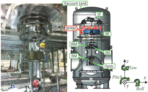
A sectional view of the Type-Bp suspension is shown in figure 3. We follow the definition of the axes shown in the figure throughout this paper.
The payload composed of the bottom two stages including optic has the same mechanism as the suspension of the Type-B system as described in [6, 10] and [11]. The payload is sus-pended from the BF stage that is sussus-pended by a single maraging steel rod from another GAS filter, called the standard filter (SF). The BFRM, the newly added RM, is suspended around the BF (see figure 4). It is an aluminum ring with about 57 kg weight suspended by three maraging rods from the ground. Each stage of the pendulum is surrounded by rigid structures called earthquake stops (EQ stops), in order to protect the suspension from serious damage caused by shocks such as one given during the installation procedure. All the suspensions and EQ stops are suspended from the traverser stage that has a set of motors to adjust the posi-tion and the orientaposi-tion of the suspension in the horizontal plane. The traverser is attached on the rigid frame inside the vacuum chamber, and is fixed on the ground independently of the vacuum chamber.
3.2. Sensors and actuators
Each stage has sensors and actuators in order to control the suspension. The actuators are used for the interferometer controls as well as local damping control. For the local active damp-ing control, several types of the sensors are employed: optical lever (Oplev) [12], an unit of a shadow sensor and a coil-magnet actuator, called optical sensor and electro-magnetic actuator
Table 1. Requirement and simulated performance of Type-Bp vibration isolation system [8].
Requirement Simulation (without BFRM) Simulation (with BFRM) Longest damping time 6.0 × 10 s 6.2 × 10² s 2.8 × 10 s
RMS velocity 6.7 µm s−1 5.3 µm s−1 1.4 µm s−1 RMS angular fluctuation 1.0 µrad 1.4 µrad 0.4 µrad
Mirror displacement at 10 Hz
(with a safety factor of 10) 5.5 ×10
−15 m
(√Hz)−1
2.9 ×10⁻¹⁵ m (√Hz)−1 3.5 ×10⁻¹⁵ m
(OSEM) [13], and two types of linear variable differential transformer (LVDT). Each stage is activelly controlled using coil-magnet actuators attached on each stage.
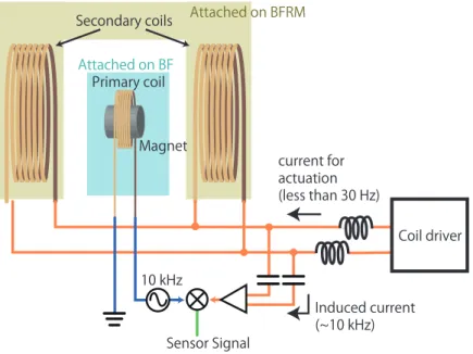
While the sensors and actuators used for the payload and the GAS filters are also same as the Type-B suspensions [6, 10, 11], the wide-range LVDTs are newly employed for the damp-ing on the BF and the BFRM stages (see figure 5). The relative position between the BFRM and the BF is adjustable only by changing the height of three suspension points. Therefore, it is important for the sensor-actuator units to be functional even when the operating point is off from the nominal position by several millimeters as well as to have a mechanism to adjust the position of the parts attached on the BFRM. They have one small coil as a primary coil which introduces modulated current, and two large coils as secondary coils which receive the induced electromotive force from the primary coil. The two coils are connected so that the induced current is ideally canceled out when the primary coil is at the center of the two coils.
Figure 3. A photo of the Type-Bp suspension (left) and a sectional view of the suspension inside the vacuum tank (right). The structure surrounded by the red dashed line is the BFRM, the new damping mechanism.
Figure 4. A photo of the BF and newly designed BFRM (left) and the corresponding CAD drawing (right). The green, yellow, and red parts are the EQ stop, the BFRM, and the sensor and actuator units for BF damping attached on the BF, respectively.
Also, the two secondary coils are used as actuator coils. The actuation current and the induced current are combined at the analog circuit. They do not disturb each other in our purpose since we actuate the suspension only at frequencies lower than 30 Hz, while the induced current stays at the modulation frequencies, such as 10 kHz.
4. Measured performance
Three Type-Bp suspensions for PRM, PR2, and PR3 optics were assembled and installed in the KAGRA site. They have already been utilized for the operation of a 3 km arm Michelson interferometer with a cryogenic test mass in May 2018, and have showed stable performance [14]. In the following sections, measured characteristics of the PR3 are described as an exam-ple of an individual performance of the Type-Bp system.
4.1. Damping control
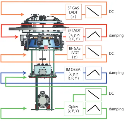
The damping control loops are engaged at all the stages for all controllable degrees of freedom as shown in figure 6. In order to minimize sensor noise introduced by the damping control, the damping servo filters are adjusted so that the open loop gain is larger than one only at around their resonant frequencies. They have large control gain at the resonant frequencies by utiliz-ing the large mechanical gain while they have low gain at higher frequencies. Other than the damping control, stages labeled as DC in figure 6 are controlled only at frequencies lower than 0.1 Hz. These loops are designed in order to compensate long-term drift of position and orien-tation of the mirror. The feedback loops are closed in each DOFs at each stage, except for the Oplev. The Oplev loop has the hierarchical control system in order to control the orientation
Figure 5. The conceptual drawing of the wide-range LVDT. The primary coil that is mounted on the BF has a magnet inside, and drive the modulation signal for LVDT sensing. The secondary coils attached on BFRM play a role of the actuation coil as well as receiver coil of the induced current. The capacitors prevent the low-frequency actuation signal contaminates the sensor signal.
of the optic. The Oplev signal is fed back to the IM OSEMs that has larger actuation efficiency than the coil-magnet actuators at the optic stage at frequencies lower than 0.1 Hz in order to compensate drift. The resonant peaks are suppressed by the feedback control from the Oplev to the optic similarly as other stages.
The suspensions are controlled by the digital system in the KAGRA site. All the signals are sampled and sent to a real-time computer via the analog-to-digital converters. After proper servo filters are applied on the signals, the feedback signals are generated at the digital-to-analog converters.
4.2. Damping time
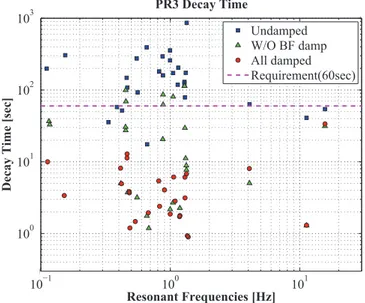
Figure 7 shows how fast the amplitude of the each resonant mode decreases. The amplitude of each mode should decay at a rate of e−t/τe, where t is time, τe is decay time that is required for the amplitude to be decreased by 1/e. The each resonant mode is excited by the actuators on the suspension, and its displacement is measured by the sensors described in the sec-tion 3.2. The Squares, triangles, and circles show the decay time τe without any controls, ones with damping controls except the BF/BFRM controls, and ones with all the damping loops on, respectively. Note that the decay time of the differential motion of the optic and the RM
Figure 6. Conceptual drawing of the damping control loop. Sensors attached on each stages measure the relative displacement in each DOFs between the main stage and its RM, and the signals are fed back to the same stage using the coil-magnet actuators. Only Oplev loop has the hierarchical structure that signals are fed back to IM stage and optic stage. The figures in the right boxes represent the schematics of the shape of the control filters.
in y -axis is not plotted in figure 7. It is the only resonant mode that cannot be observed with the local sensors. It should not affect the interferometer operation since motion in y -axis less affects the interferometer alignment, and also since there is less risk to excite this mode due to rack of actuation mechanism.
Figure 7 shows that some resonant modes cannot be damped within one minute without the BF damping system. Those modes are difficult to be observed and to be actuated by the sensors and actuators other than BF LVDT actuator units. While some of such resonant modes are motion of the BFRM that do not affect the optic motion, the whole chain mode at 0.45 Hz, for example, cannot efficiently be damped only by IM even though IM OSEMs can observe its resonance.
While all the resonances can be damped within one minutes by adding the BF damping system, the decay time of some of the resonances are longer when all damping control is on than when BF/BFRM controls are off. It is supposed to be because the BF/BFRM controls are not perfectly diagonalized to excite other resonant motions. The decay time would be shorter by further tuning of the position of the sensors and actuators and of the control filter.
4.3. Residual velocity
Figure 8 shows the residual velocity of the optic measured with the Oplev. The beam spot on the QPD of the Oplev reflected by the optic depends on both orientation and position of the optic. Each signal can be separated by using two QPDs and lenses. Please refer [12] for the detail. The velocity of the optic is derived by taking derivative of the displacement of the optic measured by the Oplev with respect to time.
The green, blue, and red lines correspond to the velocity without any damping control, with damping on except for the BF stage, and with all damping control on, respectively. The dashed
Figure 7. Decay times of resonant modes. The blue squares, green triangles, and red circles represent the decay times when the damping controls are all off, on except for the BF stage, and all on, respectively. The dashed line shows 60 s, which is the requirement on the decay time.
lines with each of the colors represent the RMS velocity of the optic with the corresponding damping control accumulated below 100 Hz.
Due to the Oplev sensing noise the only displacement of the optic observed is its resonant motion, nevertheless the measurement still provides a useful estimate of the RMS velocity. It is known that the motion at frequencies other than the resonant frequencies, contribute in small amount according to the transfer functions from seismic motion to the optic displace-ment. The total RMS of the optic velocity is 3.56 µm s−1 without any damping, 2.11 µm s−1 with damping control except for the BF stage, and 1.96 × 10⁻¹ µm s−1 with all the damping on.
The resonant peak at 0.45 Hz caused by the whole chain mode is not suppressed completely even with the BF damping system, the BFRM that is about 57 kg weight is much lighter than the BF with the weight of about 100 kg. Therefore, the BFRM follows the vibration of the main chain while some of the energy in the mode can be dissipated.
Note that dips at around 0.65 Hz are due the over-damping of the control loop on the optic stage. The open loop gain has large gain at 0.65 Hz that is the resonant frequency of the pen-dulum mode of the optic. The dip is observed in the closed loop signal since the motion caused by the resonant mode is small compared to the open loop gain.
4.4. Residual angular fluctuation
The angular fluctuation of the optic are shown in figures 9 and 10. As well as figure 8, the green, blue, and red lines correspond to the angular fluctuation without any damping control, with damping on except for the BF stage, and with all damping control on, respectively. The dashed lines with each of the colors represent the corresponding RMS angular fluctuation below 100 Hz.
Figure 8. Residual velocity of the optic monitored by the length-sensing Oplev. The green, blue, and red lines correspond to the velocity without any damping control, with damping on except for the BF stage, and with all damping control on, respectively. The dashed lines with each colors represent the RMS velocity accumulated below 100 Hz.
Without the newly designed BF damping system, the angular fluctuation in pitch can be suppressed from 3.56 × 10 µrad to 2.34 µrad, which does not satisfy the requirement, while it can be suppressed to 1.36 × 10⁻¹ µrad by employing the BF damping. It shows the pitch motion caused by the whole pendulum mode at around 0.45 Hz is effectively damped by the BF damping system.
Figure 9. Residual pitch motion of the optic monitored by the Oplev. The green, blue, and red lines correspond to the velocity without any damping control, with damping on except for the BF stage, and with all damping control on, respectively. The dashed lines with each colors represent the RMS velocity accumulated below 100 Hz.
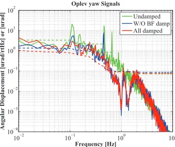
Figure 10. Residual yaw motion of the optic monitored by the Oplev. The green, blue, and red lines correspond to the velocity without any damping control, with damping on except for the BF stage, and with all damping control on, respectively. The dashed lines with each colors represent the RMS velocity accumulated below 100 Hz.
The yaw angular fluctuation that is 3.43 µrad without any damping decreased from 1.38 µ rad to less than 1.11 µrad by turning the BF damping on. The first yaw mode where the whole chain rotates without any nodes at around 0.1 Hz is suppressed efficiently by the BF damping. Note that the RMS of the yaw fluctuation with all the damping loops on shows an upper limit of the actual residual motion, since the Oplev sensing noise is too large to observe the residual resonant peaks.
4.5. Vibration isolation performance
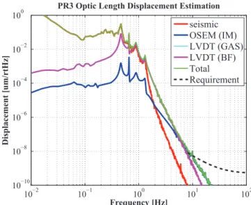
Using the rigid body model based on the measured response of the suspension [10, 11], the seismic motion, and measured sensor noise, the fluctuation of the optic in x direction is calcu-lated. The motion of the optic at higher frequencies than the resonant frequencies cannot be measured by the local sensors due to the sensor noise and the seismic motion of the sensor. Figure 11 is an estimated fluctuation of the PR3 optic. The green line is the total displacement of the PR3 optic, and the black dash line is the requirement, which is determined only above 8 Hz from the view point of the target observation band, with a safety factor of 10. It shows that the BF LVDTs have low enough noise level for PR3. The residual displacement above 10 Hz is dominated by the IM OSEM sensor noise.
5. Summary
The compact vibration isolation system with proper damping control system for PR mir-rors was realized in KAGRA. While it has relatively compact system as tall as 1.7 m, it was designed to have sufficient vibration isolation performance and damping control system. The new compact and simple damping system called BFRM is effective in terms of the damping control.
Figure 11. Estimated fluctuation in x direction of the PR3 optic when all the damping is on.
Three suspensions were installed as PRM, PR2, and PR3 in the KAGRA tunnel, and oper-ated as parts of the 3 km Michelson interferomter. Individually measured performance of the suspension is also proved to satisfy the requirements from the interferometer operation. The 1/e decay time is less than 40 s for all the resonant modes, and the residual angular fluctua-tion is less than 1 µrad. Also, the residual RMS of the optic velocity is as slow as 0.2 µm s−1, such that the momentum of the optic is small enough for lock acquisition of the optical cav-ity. Furthermore, the fluctuation of the optics caused by the seismic motion and sensor noise introduced by the damping control is also calculated to be small enough to achive the target sensitivity of KAGRA.
Acknowledgment
The Advanced Technology Center (ATC) in NAOJ supported the design and construction of the mechanical structures. This work was supported by MEXT, JSPS Leading-edge Research Infrastructure Program, JSPS Grant-in-Aid for Specially Promoted Research 26000005, MEXT Grant-in-Aid for Scientific Research on Innovative Areas 24103005, JSPS Core-to-Core Program, A. Advanced Research Networks, the joint research program of the Institute for Cosmic Ray Research, University of Tokyo, National Research Foundation (NRF) and Computing Infrastructure Project of KISTI-GSDC in Korea, the LIGO project, and the Virgo project.
ORCID iDs
A Shoda https://orcid.org/0000-0002-0236-4735
References
[1] Abbott B P et al 2016 Observation of gravitational waves from a binary Black Hole merger Phys.
Rev. Lett.116 61102
[2] Abbott B P et al 2017 Gw170817: observation of gravitational waves from a binary neutron star inspiral Phys. Rev. Lett. 119 161101
[3] Takeda H, Nishizawa A, Michimura Y, Nagano K, Komori K, Ando M and Hayama K 2018 Polarization test of gravitational waves from compact binary coalescences Phys. Rev. D 98 022008
[4] Akutsu T et al 2018 Construction of KAGRA: an underground gravitational-wave observatory
Progr. Theor. Exp. Phys.2018 013F01
[5] Abbott B P et al 2018 Prospects for observing and localizing gravitational-wave transients with Advanced LIGO, Advanced Virgo and KAGRA Living Rev. Relativ. 21 3
[6] Peña Arellano F E et al 2016 Characterization of the room temperature payload prototype for the cryogenic interferometric gravitational wave detector KAGRA Rev. Sci. Instrum. 87 34501
[7] Takamori A et al 2002 Mirror suspension system for the TAMA SAS Class. Quantum Grav. 19 1615
[8] Michimura Y et al 2017 Mirror actuation design for the interferometer control of the KAGRA gravitational wave telescope Class. Quantum Grav. 34 225001
[9] Izumi K and Sigg D 2017 Advanced ligo: length sensing and control in a dual recycled interferometric gravitational wave antenna Class. Quantum Grav. 34 015001
[10] Sekiguchi T 2015 A study of low frequency vibration isolation system for large scale gravitational wave detectors PhD Thesis University of Tokyo (https://gwdoc.icrr.u-tokyo.ac.jp/DocDB/0041/ P1504155/015/tseki_PhDThesis_main.pdf)
[11] Fujii Y et al 2016 Active damping performance of the KAGRA seismic attenuation system prototype J. Phys.: Conf. Ser. 716 12022
[12] Zeidler S 2017 Length-sensing oplevs for KAGRA Report No. JGW-T1605788 (Kashiwa: Institute for Cosmic Ray Research) (https://gwdoc.icrr.u-tokyo.ac.jp/DocDB/0057/T1605788/011/length_ sensing_oplevs.pdf)
[13] Carbone L et al 2012 Sensors and actuators for the Advanced LIGO mirror suspensions Class.
Quantum Grav.29 115005
[14] Akutsu T et al (KAGRA Collaboration) 2019 First cryogenic test operation of underground km-scale gravitational-wave observatory KAGRA (arXiv:1901.03569)
![Table 1 is a summary of the requirements on the PR mirrors. Since the requirement on the displacement of the PR mirrors are about 300 times larger than that of the SR mirrors [ 8 , 9 ], Type-Bp suspension is reasonably compact and simple](https://thumb-eu.123doks.com/thumbv2/123dokorg/5399455.57849/7.892.235.707.147.447/requirements-mirrors-requirement-displacement-mirrors-suspension-reasonably-compact.webp)
![Table 1. Requirement and simulated performance of Type-Bp vibration isolation system [ 8 ].](https://thumb-eu.123doks.com/thumbv2/123dokorg/5399455.57849/8.892.142.703.183.325/table-requirement-simulated-performance-type-bp-vibration-isolation.webp)