EUROSTEEL 2014, September 10-12, 2014, Naples, Italy
EXPERIMENTAL AND NUMERICAL ANALYSIS ON THE CORE
LATERAL THRUST IN BOLTED BRBs
Guido Bregoli, Marco Baiguera, Giovanni Metelli, Francesco Genna
University of Brescia, DICATAM, Italy [email protected]; [email protected]
INTRODUCTION
Since the 80s the research in the field of steel structures has been interested in the behaviour of innovative bracing systems, called buckling-restrained braces (BRBs) which exhibit a symmetric behaviour in tension and in compression, due to a restraining case which prevents the inner steel core to buckle. As a results, BRBs are widely used in seismic areas, owing to their capability to efficiently dissipate energy under cyclic actions. In the literature, several types of BRBs are proposed with a rectangular or cross-shaped core section embedded into a squat steel restraining case, filled with grouted mortar [1], or restrained by all-steel components [2, 3].
In the work of Gelfi and Metelli [3] a simple and economical all-steel BRB was proposed: it was composed of a rectangular section core, with buckling restrained by four L shaped bolted members, thus allowing an easy BRB assembly, as well as its inspection and the substitution of the core after a seismic event. The experimental results shown in [3, 4] pointed out the importance of the evaluation of the lateral thrusts generated by the core for the design of the bolted connections of the restraining member. Chou 2010 [4] proposed a simple expression to correlate the axial force in the BRB core to the buckled wavelength. This derives from Euler’s theory, extended to the case of elastic-plastic behaviour by replacing the Young modulus with a tangent modulus. Nevertheless, in the work of Chou and Chen [4] the measures of this thrust are not reported, and, as a result, the proposed formulation for the assessment of the lateral thrust is not validated. Furthermore, after buckling the inner core is subjected to lateral concentrated forces that are expected to modify its configuration with respect to the one associated to a simple Eulerian analysis. Therefore, the expression of the buckled wavelength adopted by Chou and Chen [4] can be considered questionable, raising doubts about its effectiveness as a tool to design the connection bolts of the BRB.
A few recent studies by Genna and Gelfi [5, 6] are aimed at investigating experimentally, numerically, and analytically the lateral thrust exerted by the inner core. The research results showed that the thrust depends on several parameters, such as the gap/core thickness ratio, the material proprieties, the amplitude and the number of the cycles of the loading history. In addition, the authors proposed an analytically formulation for estimating the lateral thrust after buckling, based on (i) the second-order theory for the calculation of the buckled shape of the core, and (ii) the use of Shanley’s theory of elastic-plastic buckling for squat columns. Firstly, the results confirmed that the buckled configuration of a core forced by lateral contact forces to stay within a fixed small gap does not obey a standard Euler’s formula, which would give buckled wavelengths much shorter than those actually measured in the tests or computed numerically [5]. In addition, the results showed that the thrust increases with the gap dimension, reaching a value up to 1.5 times the maximum axial force of the steel core. This trend, however, was not confirmed by the tests carried out on reduced scale BRBs, with a difference between numerical and experimental results even greater than 70% in some case.
In the present paper the results of a wide experimental campaign are shown. Several tests were conducted on reduced scale BRBs with a particular control of the gap dimension between the inner core and the restraining members. Furthermore, the development and the evolution of the buckled wavelengths were monitored during the cycling experiments. The experimental results are also compared to numerical results of a non-linear 3D model, which allowed the diffusion contact-phenomena caused by the local thrust and the transverse deformation of the restraining case to be
efficiently evaluated.
1 EXPERIMENTAL PROGRAMME 1.1 Test set up
The aim of the experimental campaign is to investigate the role of the gap dimension of the BRB on the lateral thrust exerted by the inner core when, after buckling in compression, it arrives into contact with the external restraining case.
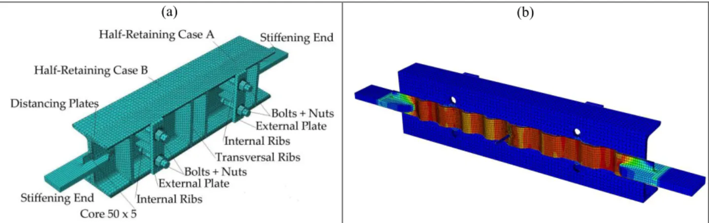
The tested BRBs comprised a rectangular 50x5 mm2 inner core with a dissipative length of 560 mm and two bolted U shaped restraining members (UPN160 commercial hot-rolled profiles) which prevented the core to buckle (Fig. 1). A steel plate welded to the web of one U member was calibrated with a tolerance of 0.05 mm to achieve the desired gap dimension, which was varied between 0.25 to 0.70 mm in the specimens. In five specimens the two half-cases were stiffened by four transverse plates in order to minimize the local deformation caused by the core lateral thrust. For a comparison, one specimen with a gap of 0.25 mm was tested removing the transverse stiffening plates of the restraining U-profiles. To reduce the friction between the core and the external case a synthetic paste containing polytetrafluoroethylene was used, providing a measured friction coefficient between the lubricated surfaces equal to ≈ 0.15 [5]. The two restraining members were connected by two pairs of M20 bolts with 10.9 steel grade (ultimate strength fub=1000 MPa and yield strength fyb=900 MPa). Each bolt was instrumented by strain gauges
applied on a 20 mm milled length (15x8 mm2 cross section) to measure the lateral thrust exerted by the core on the case during each cycle of the test. A pin with a 5 mm diameter was welded at the core centre to allow the self-weight of the case to be transferred to the inner core.
(a)
(b)
(d) (c)
Fig. 1. Test set up (a); details of restraining elements [5] (b); a specimen after testing (c) buckled shape of the core (d)
The six specimens were tested by applying to the core a cyclic axial deformation of increasing amplitude by means of a servo-hydraulic testing machine (INSTRON 1274/8500), equipped with a load cell, which provided the axial load F. A longitudinal transducer measured the axial deformation b of the dissipative length of the core. Before testing, the bolts were tightened by a
applying a force equal to 1.2 kN (corresponding to a stress of 10 MPa in the reduced cross section). A tactile sensor pressure (Tekscan) was placed between the core and the case in order to record dynamically the position and the number of the waves generated during the elastic-plastic buckling of the core, which arrives into contact with the external cases.
S275 steel was adopted for the core, with an average yield strength fym of 335 MPa, an average
ultimate strength ftm of 447 MPa, an elongation after fracture A5 = 40%, and an elongation at
maximum tensile force Agt = 22.7% (test carried out in according to EN ISO 6892-1:2009).
The displacement control loading history prescribed by AISC standards [7] was adopted: (I) two cycles with an amplitude equal to ±by with a speed rate of 2 mm/min, starting with the first
semi-cycle in the tensile direction, by = 0.95 mm being the deformation at yielding of the dissipative
length lc= 560 mm (by = fym/ Es lc = 335 /20000 x 560 mm); (II) two cycles with an amplitude equal
to ±0.5bm with a speed rate of 2 mm/min, bm = 5.6 mm being the design deformation at ultimate
limit state assuming a core elongation s =1%; (III) two cycles with an amplitude equal to ±1.0bm;
(IV) two cycles with an amplitude equal to ±1.5bm; (V) two cycles with an amplitude equal to
±2.0bm. In the last three cycles the speed rate was increased to 5 mm/min and the first cycle was
always in tension.
1.2 Test results
The main aim of the tests was the measure of the lateral thrust exerted by the core, as well as the measure of the number of the buckled waves for increasing gap dimension. As an example, among the six tests, the results of the second specimen with a gap dimension of 0.46 mm are illustrated in detail. In Figure 2.a the axial load F is plotted as a function of the applied displacement (the tensile load being positive), whilst Figure 2.b shows the transverse thrust Q measured by the instrumented bolts. In Table 1 the main results of the specimen 2 are reported for each cycle: the axial core deformation b, its average elongation, the ductility ratio =b/by, the cumulative plastic
deformation CPD = (b-by/by), and the maximum axial load, both in tension Ft and in
compression Fc for each cycle. Furthermore the total lateral thrust Q and the number n of waves
recorded by the sensor pressure in each cycle are reported. The specimen exhibited a stable hysteretic behaviour up to an average strain c = 2% with a CPD greater than minimum value of 200
required by AISC seismic provisions [7]. The tests ended after the second cycle with an axial strain c = 2% without showing the local fracture of the core or the global buckling of the BRB.
A slightly asymmetric behaviour can be observed, as the maximum force in compression reached a value of about 1.1 times the tensile force for the same applied strain, due to the friction arising when the core comes into contact with the case. This difference between the tensile load and the compression load increases with the number of core buckled waves. It should be noted that the transverse thrust is not proportional to the number of buckled waves, because it depends also on the shape of the wave itself. As an example, for the specimen 2 the measured thrust was equal to 16.5 kN with 4 buckled waves (II cycle of the 2nd loading phase), while doubling the axial displacement (II cycle of the 5th loading phase) the 8 waves were recorded associated to a thrust of about 66 kN. In Figure 2.b the unstable branches correspond to the formation of new buckled waves occurring for increasing axial deformation. The pressure sensor placed within the gap of each tested BRB allowed to record not only the number of the core waves but also their shape variation for subsequent cycles of increased amplitude. Once the buckle wave occurred, the contact zone between the core and the case extended (flattening of the core) for increased axial deformations, causing a diffusion of the inelastic core damage. As a consequence of this irreversible flattening, the core length between two contiguous flattened contact zones becomes steeper and the thrust sharply rises despite a slight increase of the axial force. The pressure sensor showed a sort of sinusoidal buckling shape with flattened lengths in the contact zone where a new wave could generate pushing against the opposite side of the restraining case, thus confirming the core behaviour described by FEM analysis [5].
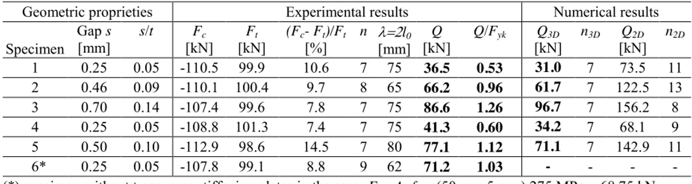
Table 2 summarizes the main test results of the six specimens, in terms of the maximum axial load in tension Ft or in compression Fc, the lateral thrust Q of the core, the number n of waves measured
at the end of the test. While the maximum axial load is similar among the specimens, the value of the transverse thrust varies from 36.5 kN for the specimen 1 with a gap of 0.25 mm to 86.6 kN in the specimen 3 with a gap of 0.70 mm. Despite the different values of the investigated gap dimension, the number of waves is always equal to 7, with the exception of specimen 2 which
developed 8 waves. As a result, it should be pointed out that the lateral core thrust depends mainly on the inclination of the buckled wave, which is affected by the gap/core thickness ratio and by plastic strains accumulated during the cyclic loading history. This trend confirms the analytical formulation proposed in [6] while it was not observed in a precedent experimental campaign [5] likely because of the incorrect evaluation of the gap dimension. Finally, it is worth pointing out the significant role of the local transverse deformation of the case on the magnitude of the lateral thrust. The specimen 6, without the stiffening plates of the case, showed a thrust twice as great as the thrust of the specimen 1, characterized by the same gap of 0.25 mm but with a stiffened case. This result was due to the higher deformation of the web U-shaped case, which allowed the growth of the gap dimension as the core started to buckle, resulting in a remarkable surge of the total lateral thrust.
Figure 3 compares the buckling core shape of the specimen 2 at the end of the test with the contour map of the contact pressures and with the buckling shape calculated by means of Finite Element analyses, described in the following paragraph.
Table 1. Test results for specimens 2 (gap s=0.46 mm)
Fase ciclo b [mm] c [%] CPD Fc [kN] [kN] Ft (Fc- F[%] t)/Ft n [kN] Q I (by) 1 ±0.95 0.17 1.0 0 -64.8 62.3 4.0 0 0.0 2 ±0.95 0.17 1.0 0 -64.0 62.1 3.0 0 0.0 II (0.5bm) 1 ±2.80 0.50 2.98 7.8 -82.1 82.1 0.0 2 3.3 2 ±2.80 0.50 2.98 15.6 -84.4 82.4 2.4 3 6.4 III (1.0bm) 1 ±5.60 1.00 5.96 35.2 -88.4 83.2 6.3 4 13.6 2 ±5.60 1.00 5.96 54.7 -93.3 84.7 10.2 4 16.5 IV (1.5bm) 1 ±8.40 1.50 8.94 86.1 -99.4 91.9 8.2 6 29.0 2 ±8.40 1.50 8.94 117.5 -100.6 95.5 5.4 7 33.9 V (2.0bm) 1 ±11.20 2.00 11.91 160.6 -106.5 97.4 9.4 8 49.8 2 ±11.20 2.00 11.91 203.8 -110.1 100.4 9.7 8 66.2 (a) (b)
Fig. 2. Specimen 2: axial load F versus axial displacement b (a); thrust Q versus axial displacement b (b)
Table 2. Comparison between experimental and numerical results for each specimen (c = 2%; 2nd cycle of 5th phase)
Geometric proprieties Experimental results Numerical results Specimen Gap s [mm] s/t [kN] Fc [kN] Ft (Fc[%] - Ft)/Ft n [mm] l0 Q [kN] Q/Fyk [kN] Q3D n3D [kN] Q2D n2D 1 0.25 0.05 -110.5 99.9 10.6 7 75 36.5 0.53 31.0 7 73.5 11 2 0.46 0.09 -110.1 100.4 9.7 8 65 66.2 0.96 61.7 7 122.5 13 3 0.70 0.14 -107.4 99.6 7.8 7 75 86.6 1.26 96.7 7 156.2 8 4 0.25 0.05 -108.8 101.3 7.4 7 75 41.3 0.60 34.2 7 68.1 9 5 0.50 0.10 -112.9 98.6 14.5 7 80 77.1 1.12 71.1 7 142.9 11 6* 0.25 0.05 -107.8 99.1 8.8 9 62 71.2 1.03 - - - - (*) specimen without transverse stiffening plates in the case; Fyk=Ac fyk= (50 mm 5 mm) 275 MPa = 68.75 kN
2 FEM MODEL 2.1 Numerical model
The numerical analyses presented in this paragraph aim at understanding the effects of the local and transverse deformation both of the restraining case and of the inner core on the lateral trust. The 3D numerical analyses were conducted adopting the FEM code ABAQUS [8].
All the components of the tested BRB were modelled by means of tetrahedral linear element with full integration, with the exception of the core for which hexahedral elements were used (Fig. 4). The components of the BRB were coupled by means of unilateral contact surfaces with Coulomb friction (= 0.15).
As in the 2D analyses [5], the steel was modelled as an elastic-plastic von Mises material with mixed (isotropic plus kinematic) hardening. The bolts were modelled as elastic-perfectly plastic with a yield strength equal to 900 MPa. The bolt tightening was modelled by imposing an equivalent thermal cooling of 1°C, which was able to simulate a pre-loading of 1.2 kN. The nodes of a core end were restrained in all directions to simulate the fixed restraint of the testing Instron machine, while at the opposite end the nodes were fixed in the transverse direction, allowing the axial displacement to be applied. The first loading step was defined applying the self-weight (370 N) of the external case, which generated an initial small imperfection of the core plate and a rigid rotation of the case. Afterwards, all the analyses were run under quasi-static loading conditions in the large strain, large displacement regime, applying to the BRB the same protocol adopted in the tests.
Measurements of the pressure sensor (a) Experimental buckled shape: 8 waves - 2l0=65 mm (b)
3D FEM anlysis buckled shape:
7 waves - 2l0=75 mm (c)
Fig. 3. Core buckling shape of specimen 2 at the end of the test: contour map of the pressure sensor (a); experimental
measured shape (b); numerical 3D finite element analysis (c) 2.2 Numerical results
Firstly, it should be noted the good agreement between experimental and numerical results for all the applied cycles, in terms of axial load, transverse thrust and buckled shape for increasing deformation of the plate core, showing the validity of the proposed 3D FEM model which was validated with all the tested specimens, varying the gap dimension between 0.25 mm to 0.70 mm. (Fig. 2, Fig. 3 and Tab. 2). The largest difference between numerical and experimental thrust occurs during the first cycles (60% difference at the II cycle with b = 0.5bm) when only two buckled
waves have developed (Fig. 2). However, as the axial deformation and the number of cycles increases, the core deformation tends to assume a periodical buckling shape along the whole dissipative length, and the calculated thrust approaches the value measured during the experiments. As shown in Table 2, the difference between the measured thrust and the thrust calculated by means of 3D-FEM analysis ranges from -8% to +17% for a strain c=2%, while with the 2D plane stress
that the plane stress model overestimates the number of buckled waves (13 waves against 8 in the test or 7 in the 3D analysis).
(a) (b)
Fig. 4: FEM model: mesh (a); core deformation for and axial strain c=2% (b)
3 FINAL REMARKS
The research work points out the significant role of the gap dimension on the value of the lateral thrust exerted by the buckled core against the restraining case. The measured lateral thrust was at least 1.0 times the nominal yield force of the core for a gap/core plate thickness ratio greater than 1/10, thus confirming the importance of the thrust assessment for a reliable design of all-steel bolted BRBs. Finally, the experimental results validated a 3D-finite element model, which allows to evaluate the thrust action with an error lower than 15%, thus showing that 3D models can be an effective tool to estimate the lateral pressure of the BRB core on the restraining case when local transversal deflections of the restraining case might widen the gap dimension.
ACKNOWLEDGMENT
The authors sincerely thank Prof. Piero Gelfi for his suggestions in the research work. Financial support for this study was provided by the University of Brescia.
REFERENCES
[1] Black C., Makris N., Aiken I., "Component testing, seismic evaluation and characterization of buckling-restrained braces", Journal of Structural Engineering, ASCE, 130:6, 880 - 894, 2004.
[2] Mazzolani F. M., "Consolidamento antisismico di edifici in C.A. attraverso tecniche innovative: il progetto ILVA-IDEM". Costruzioni Metalliche, 35 - 48, 2005, (in Italian).
[3] Gelfi P., Metelli G., Prova sperimentale di un elemento diagonale di controvento ad instabilità controllata. Proc., XXI Congresso C.T.A.: Costruire con l’acciaio, Catania, Italy, 169 – 176, 2007 (in Italian).
[4] Chou C.C., Chen S.Y., “Subassemblage tests and finite element analyses of sandwiched buckling-restrained braces.” Engineering Structures, 32, 2108–2121, 2010.
[5] Genna F., Gelfi P., "Analysis of the Lateral Trust in Bolted Buckling-Restrained Braces. I: Experimental and Numerical Results", Journal of Structural Engineering, ASCE, 138:10, 1231 - 1243, 2012.
[6] Genna F., Gelfi P., "Analysis of the Lateral Trust in Bolted Buckling-Restrained Braces. II: Engineering Analytical Estimates", Journal of Structural Engineering, ASCE, 138:10, 1244 - 1254, 2012.
[7] AISC (2010). "Seismic provisions for structural steel buildings", American Institute of Steel Construction, Chicago.
[8] Hibbitt D., Karlsson B., and Sorensen, P., ABAQUS user’s manuals, release 6.10, Dassault Systèmes/Simulia, Providence, RI, 2011.
EUROSTEEL 2014, September 10-12, 2014, Naples, Italy
EXPERIMENTAL AND NUMERICAL ANALYSIS ON THE CORE
LATERAL THRUST IN BOLTED BRBs
Guido Bregoli, Marco Baiguera, Giovanni Metelli, Francesco Genna
University of Brescia, DICATAM, Italy [email protected]; [email protected]
KEYWORDS: Buckling restrained brace, experiments; non-linear finite element analysis.
ABSTRACT
The paper aims at presenting numerical and experimental results on the lateral thrust exerted by the inner core of a buckling restraining brace (BRB) when, after buckling in compression, it arrives into contact with the external restraining case. The BRB consisted of a plate core restrained by bolted U-shaped member, thus allowing an easy assembly of the BRB, as well as the inspection and the substitution of its core after a seismic event [1, 2].
The results of six tests on BRBs having a plate core with a cross section of 5x50 mm2 and a dissipative length of 560 mm are shown. The gap dimension was varied between 0.25 and 0.70 mm. Cyclic displacements of increasing amplitude were applied to the core up to a steel strain of 2%, adopting the loading history prescribed by AISC standards [3]. The instrumented bolts connecting the restraining elements and a thin tactile pressure sensor placed within the gap allowed to steadily monitor both the lateral thrust and the buckling shape of the plate core during the experiment. The results showed that the lateral thrust increased linearly with the gap dimension, thus confirming the trend provided by the analytical formulation proposed by Genna and Gelfi [4]. As reported in Table 1, for a maximum axial force of about 110 kN, the value of the transverse thrust ranged from 36.5 kN in the specimen 1 with a gap of 0.25 mm to 86.6 kN in the specimen 3 with a gap of 0.70 mm. Furthermore, the specimens 6, without stiffening plates in the web of the restraining U-profiles, showed the significant role of the local transverse deformation on the value of the lateral thrust, which was twice the thrust of the specimen 1, characterized by the same gap of 0.25 mm but with a stiffened case.
The experimental results allowed to validate a non-linear 3D Finite Element model performed with the code ABAQUS [5]. The numerical analyses accurately predicted the cyclic behaviour of the tested BRBs in term of axial load, buckling shape of the core and lateral thrust action. The difference between the measured thrust and the calculated thrust at the end of the loading history (steel strain c=2%) ranges between -8% to +17%, while the 2D plane stress model proposed in [6]
overestimated the lateral thrust of +85%, owing to the inability of the 2D model to describe the local transverse deformations of the case.
CONCLUSIONS
The research work points out the significant role of the gap dimension on the value of the lateral thrust exerted by the buckled core against the restraining case. The measured lateral thrust was at least 1.0 times the nominal yield force of the core for a gap/core plate thickness ratio greater than 1/10, thus confirming the importance of the thrust assessment for a reliable design of all-steel bolted BRBs. Finally, the experimental results validated a 3D-finite element model, which allows to evaluate the thrust action with an error lower than 15%, thus showing that 3D models can be an effective tool to estimate the lateral pressure of the BRB core on the restraining case in particular when the local transversal deflections of the restraining case might widen the gap dimension, which in turn may affect significantly the thrust action.
(a) (b)
(c) (d)
Fig. 1 Specimen 2: axial load F versus axial displacement b (a); thrust Q versus axial displacement b (b); specimen 2 after testing (c) buckled shape of the core of FEM analysis (d)
Table 1. Comparison between experimental and numerical results for each specimen (c = 2%; 2nd cycle of 5th phase)
Geometric proprieties Experimental results Numerical results Specimen Gap s [mm] s/t [kN] Fc [kN] Ft (Fc[%] - Ft)/Ft n [mm] l0 Q [kN] Q/Fyk [kN]Q3D n3D [kN]Q2D n2D 1 0.25 0.05 -110.5 99.9 10.6 7 75 36.5 0.53 31.0 7 73.5 11 2 0.46 0.09 -110.1 100.4 9.7 8 65 66.2 0.96 61.7 7 122.5 13 3 0.70 0.14 -107.4 99.6 7.8 7 75 86.6 1.26 96.7 7 156.2 8 4 0.25 0.05 -108.8 101.3 7.4 7 75 41.3 0.60 34.2 7 68.1 9 5 0.50 0.10 -112.9 98.6 14.5 7 80 77.1 1.12 71.1 7 142.9 11 6* 0.25 0.05 -107.8 99.1 8.8 9 62 71.2 1.03 - - - - (*) specimen without transverse stiffening plates in the case; Fyk=Ac fyk= (50 mm 5 mm) 275 MPa = 68.75 kN
REFERENCES
[1] Mazzolani F. M., "Consolidamento antisismico di edifici in C.A. attraverso tecniche innovative: il progetto ILVA-IDEM". Costruzioni Metalliche, 35 - 48, 2005, (in Italian).
[2] Gelfi P., Metelli G., "Prova sperimentale di un elemento diagonale di controvento ad instabilità controllata". Proc., XXI Congresso C.T.A.: Costruire con l’acciaio, Catania, Italy, 169 – 176, 2007 (in Italian).
[3] AISC (2010). "Seismic provisions for structural steel buildings", American Institute of Steel Construction, Chicago.
[4] Genna F., Gelfi P., "Analysis of the Lateral Trust in Bolted Buckling-Restrained Braces. II: Engineering Analytical Estimates", Journal of Structural Engineering, ASCE, 138:10, 1244 - 1254, 2012.
[5] Hibbitt D., Karlsson B., and Sorensen, P., ABAQUS user’s manuals, release 6.10, Dassault Systèmes/Simulia, Providence, RI, 2011.
[6] Genna F., Gelfi P., "Analysis of the Lateral Trust in Bolted Buckling-Restrained Braces. I: Experimental and Numerical Results", Journal of Structural Engineering, ASCE, 138:10, 1231 - 1243, 2012.
![Fig. 1. Test set up (a); details of restraining elements [5] (b); a specimen after testing (c) buckled shape of the core (d)](https://thumb-eu.123doks.com/thumbv2/123dokorg/5517508.64156/2.892.84.772.581.952/test-details-restraining-elements-specimen-testing-buckled-shape.webp)